1
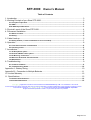
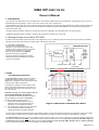
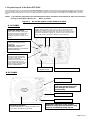
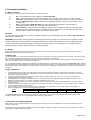
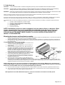
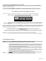
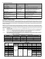
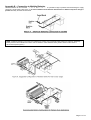
STP-3000
12V DC POWER INVERTER
OWNER'S
MANUAL
Sima Products Corporation
140 Pennsylvania Ave.
Bldg. #5
Oakmont, PA 15239
800-345-7462
www.simacorp.com
Page 1 of 14
STP-3000 Owner’s Manual
Table of Contents
1. Introduction ................................................................................................................................. 3
2. Working Principle of your Sima STP-3000 .................................................................................. 3
2.1 Principle of Operation ..................................................................................................................... 3
2.2 SIMA ............................................................................................................................................... 3
STP-3000 Output Waveform .................................................................................................................. 3
3. Physical Layout of the Sima STP-3000....................................................................................... 4
4. Permanent Installation ................................................................................................................ 5
4.1 Where to Install ............................................................................................................................... 5
4.2 Battery ............................................................................................................................................ 5
5. Cable Hook-up ............................................................................................................................ 6
5.1 Battery Cables ( if cable installation kit is not included).................................................................... 7
6. Operation .................................................................................................................................... 8
6.1 Front Panel Controls and Indicators ................................................................................................ 8
6.2 Operating Limits ............................................................................................................................. 9
7. Accessories................................................................................................................................. 9
7.1 AC Receptacle option ...................................................................................................................... 9
7.2 Remote ON/OFF switch option ......................................................................................................... 9
7.3 DC Box-Lug connectors .................................................................................................................. 9
7.4 Manual or Automatic Transfer Switch .............................................................................................. 9
7.4 Maintenance ................................................................................................................................... 9
8. Troubleshooting .......................................................................................................................... 9
8.1 Common Problems.......................................................................................................................... 9
8.2 Troubleshooting Guide .................................................................................................................. 10
Appendix A - Battery Sizing .......................................................................................................... 10
Appendix B – Connection to Multiple Batteries ..............................................................................11
10. Limited Warranty ..................................................................................................................... 12
11. Specifications .......................................................................................................................... 12
11.1 Electrical Performance ................................................................................................................. 12
11.2 Product Dimensions .................................................................................................................... 12
STP and Sima logos and combinations thereof trademarks of Sima Products Corp., Ltd. or its subsidiaries in all countries.
All other products and names mentioned herein may be property, trademarks or registered trademarks of their respective companies & owners.
Entire contents copyright of Sima products Corporation Inverter Owner’s Manual © 2005Sima Products Corporation
All rights reserved. Reproduction in whole or in part without permission is prohibited.
Page 2 of 14
SIMA STP-3000 12V DC
Owner's Manual
1. Introduction
Your new Sima STP-3000 inverter is the most advanced DC to AC inverter available today from the SIMA family. It is designed to give you years of
dependable services everywhere in your RV, boat, service vehicle, office, shop or remote home.
Proper installation of the Sima STP-3000 is needed to obtain its best performance as instructed in this installation and operation manual. Please read
carefully before installing and using your Sima STP-3000. Statements marked 'CAUTION' and 'WARNING' in this manual call for special attention
about the Sima STP-3000.
“CAUTION” statements identify conditions or practices that could result in damage to your Sima STP-3000 or to other equipment.
“WARNING” statements identify conditions or practices that could result in personal injury or loss of life.
2. Working Principle of your Sima STP-3000
A Power Inverter electronically converts electricity of low voltage DC to 115V AC. Advanced power conversion technology has been incorporated in
the design of Sima STP-3000, leading to a smaller, lighter, and easier-to-use inverter.
2.1 Principle of Operation
The Sima STP-3000 first raises low
voltage DC to 145 volts DC using modern high
frequency power conversion techniques, and then
converts the high voltage DC into 115 volts,
60Hz AC using advanced power MOSFET
transistors in full bridge configuration.
High surge capability to operate tough reactive
loads like fluorescent lamp ballasts and inductive
motors are incorporated.
170 V DC
INVERTER SECTION
+
DC INPUT
DC-DC
CONVERTER
POWER
MOSFET
CHASSIS GND GND
NEUT
LINE
AC OUTPUT
Figure 1. SIMA STP-3000 – Principle of operation
2.2 SIMA
STP-3000 Output Waveform
GND
LIN
The Sima STP-3000 generates "Quasi-Sine Wave" or
"Modified Sine Wave" waveform for its AC outputs
(Figure 2). It is designed to have characteristics similar
to the sine wave shape of utility power.
This waveform is suitable for most AC loads found in
electronic equipment, transformers, and motors. It is
also superior to the square waves produced by other
DC to AC inverters.
CAUTION: Do NOT Use Sima STP-3000 with the
following RECHARGEABLE APPLIANCES
Some rechargers for small nickel cadmium batteries
can be damaged if connected to the STP-3000
including the following equipment types:
1). Small battery operated appliances such as
flashlights, razors, and night-lights that plug
directly into an ac receptacle to recharge.
2). Some battery pack chargers for hand power tools
with warning labels stating that dangerous
voltages are present at the battery terminals.
Figure 2. Waveform of Modified Sine Wave
The vast majority of battery-operated equipment uses separate chargers or transformers that are plugged into AC receptacle to produces low voltage
outputs and hence would not have this problem. SIMA’s STP-3000 will power safely with less than 30-volt dc-output adapters or chargers.
The Sima STP-3000 is designed to have a True RMS (root mean square) voltage of 115 volts, the same as AC power. Most digital and analog AC
voltmeters are calibrated to the MEAN of the waveform rather than the true RMS value and such meters will not read the true RMS voltage of a
modified sine wave correctly. True RMS reading voltmeters (such as Fluke 87, Fluke 189, Fluke 8060A, Beckman 4410, or Tektronix TDS 220)
must be used to accurately measure the output voltage of your Sima STP-3000.
Page 3 of 14
3. Physical Layout of the Sima STP-3000
Power flows logically from the rear terminals of the Sima STP-3000 unit forward to the front panel of the AC output receptacle (or optional junction
box). All indicators, controls, and output connections are conveniently accessed from the front panel (See Figure 3a and Figure 3b). Their detail
functions are explained in Section 6.1 below. A circulating fan draws cooling-air in from the rear and forces the flow out through vents on the front
panel.
NOTE:
It is extremely important to provide adequate airspace around the unit surfaces to allow for convection
cooling as described in Section 5.1 – Where To Install.
Figure 3.
AC and DC panels of the SIMA STP-3000
A. AC PANEL
OVERLOAD INDICATOR:
Lights when inverter shuts down
because of severe overload. Turn
inverter off. Remove cause of
overload, and turn inverter on to
reset .
BAR GRAPH METERS:
Display battery voltage and current. Current should be in the
GREEN zone ONLY for continuous operation; The inverter will
operate for several minutes when the current in the Yellow zone:
operation with battery voltage or current in the red zone of the
meter will result in protective shutdown of the inverter.
ON/OFF SWITCH:
Leave in OFF position during
installation
CAUTION! THIS IS NOT A
DISCONNECT SWITCH.
REMOVE POWER AT THE SOURCE
BEFORE SERVICING.
OVER TEMP INDICATOR:
Inverter is shut down while
indicator is ON. Inverter will
restart automatically.
Indicator lamp and alarm will
turn off when the inverter
cools. Lights and alarm alerts
when inverter protects itself
against OVERHEATING.
Modular jack
for Remote control
AC GFI outlet (Inverter output)
B. DC PANEL
RED: Positive “+”
CAUTION: Reverse polarity
will open internal fuses and
MAY damage the inverter
permanently
BLACK: Negative “-”
CHASSIS GROUND LUG.
Ventilation Opening
DO NOT OBSTRUCT – Allow at least 4 inch
(100 mm) clearance for air flow.
WARNING: Operation of the inverter
without a proper ground connection may
result in an electrical safety hazard
Page 4 of 14
4. Permanent Installation
4.1 Where to Install
The following environmental requirements are essential for installing the inverter:
a)
b)
c)
d)
e)
Dry - Do not allow water to drip or splash on the Sima STP-3000.
Cool – Ambient air temperature should be between 0°C and 40°C (32°F and 105°F). The cooler, the better.
Ventilated – Ensure that the unit is in a compartment that is ventilated. Allow at least 2 inch (5cm) of clearance
around the Sima STP-3000 for airflow. Make sure that ventilated openings on the front and rear of the unit are
not obstructed.
Safe – Do not install the SIMA STP-3000 in the same compartment as batteries or any place likely to
accumulate flammable liquids such as gasoline (See warning below).
Close to Battery – Install as close to the battery as possible so as to minimize the length of connecting cable
between the inverter and the battery. Do not install in the same compartment. It is more efficient to allow longer
AC wires than DC cables due to smaller current flows in the AC wires.
CAUTION!
To reduce fire hazard, do NOT cover or obstruct ventilation openings. To avoid overheating, DO NOT install the Sima STP-3000 in a
zero-clearance compartment.
WARNING! This equipment contains components that tend to produce arcs or sparks. To reduce risk of fire or explosion, do NOT
install in compartments containing batteries or flammable materials or in places where equipment needs to be ignition-protected.
The STP-3000 may be mounted horizontally or vertically on flat surfaces using the mounting flanges on the panels. Mounting
hardware should be corrosion resistant and of #10 or larger in diameter.
4.2 Battery
Battery performance strongly affects outputs from your Sima STP-3000 and correct battery size and type must be utilized. Selection criteria of
batteries are listed below for your specific applications.
A. Battery type
The lead-acid battery of your automobile can deliver large current for a short duration, consuming a small portion of its capacity to start up the engine.
It is not suited for repeated charge-discharge cycles as such services quickly wear out the battery life.
Deep-cycle lead-acid batteries are marketed for repeatedly discharge and recharge cycles as used in recreational vehicles, boats, and electric golf
carts. They are referred to as RV, marine, or golf-cart batteries.
It is recommended that deep-cycle batteries be separated from starting batteries by battery isolators when using the Sima STP-3000. Battery isolators
are solid-state electronic circuits available at marine/RV dealers and most auto-parts stores. They allow appliances be operated from auxiliary sources
without discharging the vehicle's battery and automatically direct the charge from the alternator to the battery when the vehicle operates (See Figure 5
on page 11).
B. Tips on Batteries
1
2
3
4
5
6
Lead-acid batteries emit hydrogen and oxygen gases, and sulfuric acid fumes when recharging. Vent the battery compartment to prevent
accumulation of these gases, and do not install electronic or electrical equipment in the battery compartment. Do not smoke or carry an open
flame when working around batteries.
The capacity of lead-acid batteries is temperature sensitive. Battery capacity is rated at 25°C (77° F). At –20° C (0°F) the ampere-hour
capacity will be about half the rated capacity.
Discharged batteries will undergo a “SULFATION" process, becoming permanently damaged. Recharge immediately within a day or two.
Batteries shall self-discharge in 3 to 6 months. Recharge periodically even if not in use.
Check the electrolyte fluid level once a month for batteries requiring maintenance and replenish with distilled water. Overcharging results in
excessive fluid loss.
Permanent connectors with reliable and low resistance connection must be made to the battery posts. Do not use "alligator" clips. Connections
must be regularly cleaned to prevent corrosion.
Check the battery states with a hydrometer or a voltmeter. Measure the (12-volt) battery a few hours after charging or discharging. For
deep-cycle batteries at 25°C (77°F), the following table may be used:
Battery Voltage
12.7 ~ 12.9
12.5 ~ 12.6
12.3 ~ 12.4
12.1 ~ 12.2
11.9 ~ 12.0
Table 4.
State-of-Charge
100%
80%
60%
40%
20%
Your Sima STP-3000 may be connected directly to the vehicle starting battery only if it drives small loads (less than 250/300 watts) for short
discharging duration (less than one hour) Immediate battery recharge is recommended.
C. Alternators and Charging Systems
Battery health can only be maintained with good charging systems. Recharge your deep cycle batteries when they are 50% discharged so as to
ensure long battery life.
Heavy-duty high-output alternators are available from RV/marine dealers and auto-parts suppliers. They produce 100 to 140 amperes of current at
high voltages to charge multiple battery systems.
Page 5 of 14
5. Cable Hook-up
CAUTION!
Loose connectors result in excessive voltage drop and may cause overheated wires and melted insulation.
CAUTION!
Reverse polarity connection (positive to negative) will blow the fuses in the Sima STP-3000 and may permanently
damage the inverter. Damage caused by reverse polarity connection is not covered by your warranty.
WARNING!
Spark may be observed when connection is first made as current starts to charge up capacitors in the Sima STP-3000.
Do not make this connection in the presence of flammable fumes. Explosion or fire may result.
Cables connecting the inverter to the DC power source must be as short as possible and sufficiently large for the required current flow so as to
minimize the voltage drop and to maintain high efficiency of the overall system.
Sima’s STP-3000 comes with a basic wiring kit to permanently install your inverter to a single battery. Multiple battery installation like the examples
that follow in our manual require additional cables and connectors that are not supplied and have to be purchased before installation.
The supplied cables come with pre-installed ring terminals for connection from the STP-3000 to your battery. The cable kit includes the following
items.
1. 1pc RED (+ POS) wire (80mm^2) 1.0 meter in length
2. 1pc RED (+ POS) wire (80mm^2) 0.5 meter in length
3. 1pc BLACK (- NEG) wire (80mm^2) 1.5 meters in length
4. 1pc GREEN (- ground) wire.
5. Fuse block assembly
6. 2 pieces 250 Amp fuses
NOTE: Installation requires an open workspace free from obstructions or obstacles. Wear
proper eye protection. If you are not qualified to install high power devices or if you are
unsure of the proper safety precautions needed to install a high power device like the
STP-3000 then STOP RIGHT HERE! CONTACT A LOCAL INSTALLATION EXPERT TO
INSTALL YOUR INVERTER.
Mounting the inverter and fuse block assembly:
1.
2.
Make sure the inverter is turned off. Select an inverter location that is free from water and combustible fumes. You will need to purchase the
necessary hardware bolts/nuts, screws…etc for your particular installation.
Select fuse block location. Location must be less than 0.5 meters from battery and less than 1.0 meters from the inverter. Assemble fuse
block assembly with supplied bolts/nuts. Make sure you install and secure the fuse. Mount fuse block with supplied sheet metal screws to
your chosen location.
Connecting the wires – refer to Fig. 4 at right:
3.
4.
5.
6.
7.
8.
Connect one end of the supplied GREEN wire to the Earth Ground
connection on the DC side of the inverter.
Connect the other end of the GREEN wire to a secure location on
vehicle chassis.
Connect one end of the BLACK wire to the – NEG connection on
your battery. Most MARINE type batteries have a STUD type mount
in addition to a CLAMP type mount that can be used with the ring
terminal. If your battery only has the CLAMP type connections you
will need to purchase an adapter from your local auto parts or
battery supply store to use the supplied cables. Secure with
supplied lock washer and nut that came with your battery or adapter.
Connect the other end of the BLACK wire to the – NEG connection
on the inverter. Secure with supplied lock washer and nut.
Connect one end of the shorter 0.5 meter RED wire to the end of
the supplied fuse block that is closest to your battery. Secure with
Fig. 4
supplied lock washer and nut
Connect the other end of the shorter 0.5 meter RED wire to the +
POS connection on your battery. Most MARINE type batteries have
a STUD type mount in addition to a CLAMP type mount that can be used with the ring terminal. If your battery only has the CLAMP type
connections you will need to purchase an adapter from your local auto parts or battery supply store to use the supplied cables Secure with
supplied lock washer and nut that came with your battery or adapter.
NOTE: Steps 9 & 10 are your final connections to supply power to your inverter. Making this connection will
create a spark. Make sure the last connection is to the supplied fuse block. Make sure the inverter is turned off
before you continue. Make sure you are wearing adequate eye protection.
9. Connect one end of the longer 1.0 meter RED wire to the + POS connection on the inverter. Secure with supplied lock washer and nut.
10. This connection will create a spark: Connect the other end of the longer 1.0 meter RED wire to the end of the supplied fuse block that is
closest to the inverter. Secure with supplied lock washer and nut.
Safe operation of the Sima STP-3000 requires a solid, low resistance connection to the DC power
source.
Page 6 of 14
5.1 Battery Cables ( if cable installation kit is not included)
Safe operation of the Sima STP-3000 requires proper wires. Low resistance wiring from the battery to the Sima STP-3000 is
essential to deliver high input currents at low supply voltages. Do not undermine the maximum efficiencies from your inverter and
batteries with undersized copper wires.
It is recommended using 2 x # l AWG or 1 x 3/0 AWG copper cable (90°C insulation rating) as the minimum size for battery
connections to the Sima STP-3000. Minimize cable length to less than 10ft (3 meters) in order to maintain overall efficiency.
Lower efficiency results in shorter battery run-times.
Inverters may shut down below 10-volts if excessive voltage drops across the battery cables. See Table 5 for cable length and sizing.
Table 5: Recommended DC Cables Sizes for Permanent Installation, for voltage drop
less than 0.5Vdc total. Based on 90°C Cable.
Length of
each Cable
Up to …
10ft. (3m)
15ft. (4.6m)
20ft. (6.1m)
SIMA STP-3000
Minimum Cable Size if Minimum Cable Size if
Using Single Cables
Using Double Cables
No. 3/0 AWG
2 x No.1 AWG
250 MCM
2 x No. 2/0 AWG
400 MCM
2 x No. 3/0 AWG
Use cables rated at 90°C. For cables rated below 90°C or run in conduit, refer to your local and national electrical codes.
CAUTION! Based on Table 310-17 of the U.S. National Electrical Code (NFPA 70), 1993, and on Table 1 of the Canadian Electrical
Code, Part 1.
Connect the supply cables to the DC terminals on the Sima STP-3000 via 5/16-inch ring terminals fixed to the cable with insulation stripped off over a
length of 1/2 inch (1.25cm) from the ends. Crimp the ring terminals properly. Equivalent cable box-lug terminals (available at electrical parts suppliers)
may also be used with the bare cable end inserted into the lug terminal. Secure the other cable ends to the battery terminal posts with lugs or
connectors to ensure low resistance connection.
Proper safe operation of the Sima STP-3000 requires solid, low resistance connection to
the DC power source.
Do NOT Tin the Cable Ends with Solder. Doing So Will Result in Poor Long-Term Connection!
CAUTION!
The Sima STP-3000 must be connected only to batteries with a nominal output voltage
of 12-volts. It will not operate from a 6-volt battery, and will be damaged if connected to a 24-volt battery.
5.2 AC Wiring Connections
Warning: If you are unfamiliar with high voltage wiring or unsure about how to connect this
inverter, it is recommended that a qualified electrician install this inverter.
1.
WARNING!
Manual or automatic transfer switch may alternatively be used (See Figures 11 and 12). A transfer switch is a break before
make, double pole, double throw (DPDT) switch that switches both the hot and neutral wires of the AC distribution system
from one power source to the other. Manual and automatic transfer switches are available from marine and RV dealers.
They are commonly used to switch between a generator and AC (utility) power. Purchase an agency-approved switch that
exceeds the output ratings of both the inverter and the other source.
2. Do not connect the Sima STP-3000 and another AC source (such as a generator or utility power) to the AC wiring at the
same time. The Sima STP-3000 will be damaged if its output is connected to AC voltage from another source. Damage can
occur even if the STP-3000 is switched off.
When installing the inverter into electrical systems with other power sources, a switching means MUST be included between
the STP-3000 and the other power source so that it disallows connection to both sources at the same time. This can be a
plug inserted into the desired AC power source (See Figures 10 on following page.)
3. Do not connect the Sima STP-3000 to an AC branch circuit that has high-power consumption loads. The Sima STP-3000
WILL NOT operate stoves, and other electrical appliances that consume more than 2500 watts.
Do not attempt your own AC wiring unless you have the knowledge and experience to do a safe job. Your RV or boat
dealer, or a licensed electrician can do the job for you if you do not wish to do your own wiring.
Page 7 of 14
B. Ground Wiring
The Sima STP-3000 has a lug on the rear panel to connect the chassis of the inverter and its AC output ground to the AC distribution
system ground. This chassis ground lug must be connected to a grounding point, such as the chassis ground of a vehicle, or the
grounding system of a boat, or the earth ground via a ground rod (a metal rod pounded into the earth), or other proper service entrance ground. Use a # 8 A WG or larger copper wire (preferably with Green/Yellow insulation) to connect the chassis ground lug to
the grounding point. The neutral (common) conductor of the Sima STP-3000 AC output circuit is also connected to chassis ground to
conform to the National Electrical Code requirements. Set the ON/OFF switch on the Sima STP-3000 to the ON position. Check the
battery voltage indicator if it indicates within 12 to 13-volts. If it does not, check your battery and connections to the Sima STP-3000
inverter. The other indicators should be off.
WARNING!
Do not operate the Sima STP-3000 without connecting it to ground. Electrical shock hazard may result.
6. Operation
Switch ON the Sima STP-3000 from the front panel to operate the inverter. It is now ready to drive AC loads. Turn each appliance on individually for
multiple operations after switching on the STP-3000 inverter so as to reduce the simultaneous starting currents from all loads.
6.1 Front Panel Controls and Indicators
A. ON/OFF Switch
The ON/OFF switch turns the control circuit of the Sima STP-3000 ON and OFF (See Figure 3). It does not disconnect DC power from the battery to
the Sima STP-3000 inverter.
The Sima STP-3000 consumes about 0.2mA of current from the battery with the switch at the OFF position. It draws less than 700mA of no-load
current from the battery with the switch at the ON position. A 100 ampere-hour battery can last more than a week discharging at this low current level.
Switch the inverter off if battery is not recharged within a week or so.
B. Remote ON/OFF Jack
The Sima STP-3000 supports remote ON/OFF switch via an optional jack which allows users to switch the inverters ON or OFF away from the
installation panel (See your SIMA dealer for more details on the STP-3000 Remote ON/OFF switch).
C. Battery Voltage Indicator
This indicator displays the input voltage to the Sima STP-3000 inverter. It gives
readings close to the battery voltage for low input currents but gives lower readings
than the battery voltage due to voltage drops across cables and connections for high
input currents.
The Sima STP-3000 inverter may shut down when voltage goes into the red area at
the top or bottom of the indicator. Normal operations should register readings in the
green zone.
D. Battery Current Indicator
It displays the current drawn from the battery by the Sima STP-3000 only.
Normal operations register current readings in the green area with transient
operations occasionally in the yellow zone. If current level goes to the red area, the
STP-3000 will reduce its output voltage to protect itself.
E. OVERTEMP Indicator
Overheating of the Sima STP-3000 results in shutting-down itself, lighting up the OVERTEMP indicator, and sounds the alarm buzzer.
Over-temperature is result of operating power ratings over 2500 watt continuous output or being installed in poorly ventilated location. It will
automatically restart after cooling down .
F. OVERLOAD Indicator
Overloading the Sima STP-3000 shuts the inverter down with the OVERLOAD indicator signaled. Reset the invert to OFF position, then clear the fault
(remove/unplug the load), before switching the ON/OFF switch back to ON.
Page 8 of 14
G. ALARM Indicator –Audible alarms will sound off if any of the following conditions occur:
a)
b)
c)
OVERTEMP condition
Low Battery Voltage : <10.7V
Low Volt. Shutdown : <10.0V
6.2 Operating Limits
A. Power Output
The Sima STP-3000 delivers 2500 watts or 22.7 amperes continuously and about 3000 watts or 27.3 amperes for approximately 5 minutes. The Sima
STP-3000 must be cooled down for minimum 15 minutes before it resumes operation at 2500 / 3000 watts. Wattage rating is for resistive loads like
heaters while current rating is for reactive loads like motors.
It operates most AC loads within these ratings and will normally start single-phase induction motors rated at 1HP or less. It fails to start large inductive
motors due to huge starting currents.
If the battery voltage indicator drops below 11 volts when the Sima STP-3000 is attempting to start a motor, it would not start. Ensure proper battery
connections and being fully charged. Larger batteries may be needed if voltage still drops below 11 volts. See battery-sizing notes in Appendix A.
B. Input Voltage
The STP-3000 operates with input voltage between 10 ~15-volts. Its optimum performance ranges with input voltage between 12.0- and 14.0-volts.
Low battery warning will sound with the voltage indicator in the lower red zone when input voltage drops below 10.7 volts. Voltage below 10 volts shall
shut down the inverter in order to protect your batteries from being over-discharged. It takes an input voltage above 11-volts to restart the STP-3000
inverter.
Input voltage above 15-volts also shuts down the inverter so as to protect the unit from excessive input voltage. The voltage indicator will be in the
upper red zone. Avoid input voltages exceeding 16-volts as it may damage the inverter permanently.
7. Accessories
7.1 AC Receptacle option
The AC receptacle on front panel of the Sima STP-3000 inverter offers ready access to AC power for outputs limited to 1500 watts (15A) per outlet.
7.2 Remote ON/OFF switch option
This option allows the Sima STP-3000 inverter be turned on and off from a remote switch positioned up to 20 feet (6.1 meters) away, with push-button
and indicator light showing inverter status (See your SIMA dealer for more details on the STP-3000 Remote ON/OFF switch).
7.3 DC Box-Lug connectors
Available at electrical parts suppliers, box-lug connectors may be used in place of ring terminals.
7.4 Manual or Automatic Transfer Switch
To select between power sources from inverter, generator or utility power, use manual or automatic transfer switches. The double-pole, double-throw
(DPDT) switch breaks the load from one power source before making connections to another (See Section 5.2). Transfer switch is available from
marine and RV equipment dealers. Purchase only agency-approved switch that covers both ratings of the inverter and the other power source
7.4 Maintenance
Your Sima STP-3000 requires very little maintenance. Clean the exterior periodically with a damp cloth to prevent accumulation of dust and dirt,
especially for the air intake on the rear panel and exhaust slots on the front panel to remove accumulation of dust and dirt. Regular maintenance
check is recommended. Tighten screws on the DC input terminals periodically.
8. Troubleshooting
8.1 Common Problems
A. Buzz in Audio Systems
Portable stereo systems may not adequately filter the modified sine wave, thus producing buzzing noise from their loudspeakers when powered by
Sima STP-3000 inverter. Sound systems with higher quality power supplies are recommended.
B. Television Interference
Television reception may be interfered when operating the Sima STP-3000 inverter. Observe the following steps to alleviate the problem:
1
Secure the chassis ground lug on the rear panel of the Sima STP-3000 solidly to the ground system of your vehicle, boat and home.
2
Do not operate high power loads simultaneously while watching television.
3
Ensure the antenna feeding the television set with adequate (“snow free”) signal and that good quality cable feeding the television.
4
Keep a distance between the televisions from the Sima STP-3000 inverter.
5
Minimize the cable length between the battery and the Sima STP-3000 with twists so as to minimize the radiated interference from the
cables.
Page 9 of 14
8.2 Troubleshooting Guide
Problem and symptoms
Possible Cause
Low output voltage
(96 to 104 V AC)
Low output voltage and current
indicator in red zone.
No output voltage and
voltage indicator in lower red zone
No output voltage,
no voltage indication.
Using an
voltmeter.
Overload.
average
Low input voltage.
Solution
reading Use true RMS reading meter. See section 2.2
of manual
Reduce load.
Recharge battery, check connections and cable.
1. Inverter switched off.
2. No power to inverter.
3. Internal fuse open.
4. Reverse DC polarity.
1. Turn inverter on.
2. Check wiring to inverter. Check battery fuse
3. Have qualified service technician check and replace.
4. Have qualified service technician check and
replace fuse, Observe Correct Polarity.
High input voltage.
Make sure that STP-3000 is connected to 12V
battery, check regulation of charging system.
Poor DC wiring, poor battery Use proper cable and make solid connections.
condition.
Change battery or use new battery.
Thermal shutdown.
Allow the STP-3000 to cool off. Reduce load if
continuous operation required.
No output voltage,
voltage indicator in upper red zone.
Low battery alarm on all the time,
voltage indicator below 11V.
No output voltage, OVERTEMP indicator
on, load in excess of 3000W with 250/300A
input current.
No output voltage, OVERTEMP indicator on, Thermal shutdown.
load less than 3000W with
300A input current.
OVERLOAD indicator on.
1. Very high power load.
Improve ventilation, make sure ventilation openings in
The STP-3000 are not obstructed, reduce ambient
temperature.
1. Remove or reduce load.
Appendix A - Battery Sizing
For continuous usage, deep-cycle batteries are rated by reserve capacity in minutes or by ampere-hour capacity. Reserve capacity measures the
duration a battery delivers its rated current – normally at 25 amperes. A battery of 60 minutes reserve capacity can deliver 25 amperes for 60 minutes
before completely discharged. The measure of cranking amperes used to rate starting batteries in automotive is not suitable for deep-cycle batteries.
It is better to size your batteries more conservatively for unexpected variations. More reserve capacity means your batteries will not be discharged as
deeply so that battery life will not be unduly shortened. It is recommended that the consumed ampere-hour loading should be kept less than 50% of
the battery's rated capacity.
Ampere–hour (AH) capacity measures battery amperage being delivered for a rated duration – normally at 20 hours. A typical marine or RV battery
rated for 120 ampere–hour delivers 6 amperes for 20 hours.Battery capacity varies inversely with discharge current. At 5 amperes loading, a battery
of 100AH discharges for 20 hours but at 20 amperes loading, the same battery may only last for 4 hours with its capacity reduced to 80 ampere-hours.
It is therefore not suitable to compare rated ampere-hour capacity directly with battery reserve capacity.Observe the following steps to determine your
battery capacity requirements:
STEP 1 Determine the wattage of each appliance to be driven by the Sima STP-3000. Multiply any current ratings by 115 to obtain the power
consumption in watts.
STEP 2 Estimate duration of tool operation between battery charge-discharge cycles or each appliance being driven by the Sima STP-3000.
STEP 3 Calculate the total watt-hours of operations, total running time in hours, and average power consumption as exemplified below:
Average Power Consumption = 3275 watt-hrs ÷ 1.8 hours = 1819.44 watts
For Sima STP-3000 inverter, Ampere-Hour Consumed = 3275 ÷ 10 = 327.5 ampere-hours
STEP 4 Locate the battery size meeting the required operating time at the calculated power consumption level from Table 3. For the example
shown, operation duration of 1.8 hours at 1819.44 watts requires the smallest battery size as two 400 amp-hr batteries in parallel,
offering about 10 to 12 hours of operating time.
Table 3. 12-Volt Battery Sizing Chart (for reference only)
Equipment
Coffee Maker
Cordless Steam Iron
Vacuum Cleaner (380W)
Washing Machine
Window Type (12100Btu/h)
Totals
Inverter
output
power
(watts)
50
100
200
300
400
600
800
1000
1200
1500
2000
2500
2950
Typical Load
Stereo system
19” colour TV
Computer system
Blender
Power drill
Small coffee maker
Small microwave
Automatic Toaster
Cordless Steam Iron
Full size microwave
Grill Microwave
Oven 42L(1.5Cu.ft)
Hair dryer &
washing machine
Window Type
(12100Btu/h)
Example for Step 3 of Battery Sizing
Power Consumption
Operating Time
1000 watts
0.3 hour
1200 watts
0.5 hour
1600 watts
0.25 hour
2000 watts
0.25 hour
2950 watts
0.5 hour
1.8 hours
AMP-HRS:
Reserve
capacity
50
Watt Hours (Power x Operating Time)
300
600
400
500
1475
3275 watt-hours
BATTERY SIZE
75
100
200
400
90 minutes
140 minutes
180 minutes
400 minutes
900 minutes
9 HOURS
4 HOURS
2 HOURS
1.3 HOURS
1 HOUR
14 HOURS
6 HOURS
3 HOURS
2.2 HOURS
1.5 HOURS
20 HOURS
10 HOURS
4.5 HOURS
3 HOURS
2 HOURS
1 HOUR
40 HOURS
20 HOURS
10 HOURS
6 HOURS
4.5 HOURS
2.5 HOURS
1.5 HOURS
1 HOUR
0.5 HOUR
0.5 HOUR
80 HOURS
40 HOURS
20 HOURS
12 HOURS
10 HOURS
6 HOURS
4 HOURS
3 HOURS
2 HOURS
2 HOURS
N.R.
N.R.
N.R
0.3 HOUR
1 HOUR
0.2 HOUR
0.7 HOUR
0.15 HOUR
0.5 HOUR
Operating
time
Page 10 of 14
Appendix B – Connection to Multiple Batteries
Identical batteries can be connected “+"to“+"and“–"to“–" in a parallel for larger capacities while maintaining the supply
voltage of a single battery (See Figure 7). Do not mix batteries from different manufacturers or different amp-hour ratings in
parallel as battery life would be shortened.
NOTE: If different batteries or more than two batteries are needed, set up separate battery banks and use them separately.
Battery selectors are available from marine and RV dealers to select between battery banks. Switch to either bank or
disconnect all (See Figure 8.)
Page 11 of 14
10. Limited Warranty
Sima Products Corporation (“Company”) warrants that if the accompanying product proves to be defective to the original purchaser in
material or workmanship within 90 days from the original retail purchase, the Company will, at the Company’s option, either repair or
replace same without charge (but no cash refund will be made). If the product is returned within three (3) years from the original date
of purchase, the Company will repair or replace the unit, however, a standardized labor-only fee will be charged. The Company will
not charge a fee for any parts used in the repair. The Company will notify you of any fees to be assessed prior to servicing the unit.
What you must do to enforce the Warranty: You must deliver, mail or ship the product, together with the original bill of sale and this
limited Warranty statement as proof of warranty coverage to:
Sima Products Corporation
Attn: Customer Service
140 Pennsylvania Ave., Bldg. #5,
Oakmont, PA 15139
Call customer service (800-345-7462) before sending the unit in for service.
Limitation of Liability and Remedies
Sima Products Corporation shall have no liability for any damages due to lost profits, loss of use or anticipated benefits, or other
incidental, consequential, special or punitive damages arising from the use of, or the inability to use, this product, whether arising out
of contract, negligence, tort or under any warranty, even if Sima Products Corporation has been advised of the possibility of such
damages. Sima Products Corporation’s liability for damages in no event shall exceed the amount paid for this product. Sima
Products Corporation neither assumes nor authorizes anyone to assume for it any other liabilities.
©2005 Sima Products Corporation
IMPORTANT:
The Warranty will be VOID automatically once ANY one of the followings did occur:
1. If you connect the wires to wrong terminals, the polarity will be reversed and this will damage the unit immediately. Reversed
polarity will instantly void your product’s warranty;
2. Connecting the inverter’s input to a battery charger will damage the inverter and the relevant warranty is treated be voided
immediately;
Remarks:
All returns must have a Return Authorization Number (RAN) issued prior to sending back or SIMA and or her dealer(s) can not
accept the shipment.*Terms & conditions are subject to change without prior notice*
This is SIMA’s only warranty, and The Company makes no warranties, express or implied, including warranties of merchantability and
fitness for a particular purpose.If your product requires further service and you are unable to contact your local dealer, or the dealer is
unable to provide your with the expected service, you may contact SIMA at www.simacorp.com
11. Specifications
11.1 Electrical Performance
Description
Output Power
The first 5 minutes:
Continuous:
Output voltage:
Output waveform:
Output frequency:
Input voltage:
Low battery alarm
Low battery shutdown:
Optimum efficiency:
No-load current draw without fan:
Switch ON
Switch OFF
Sima STP-3000
3000 watts
2500 watts
115 VAC RMS ± 5%
Modified sine wave.
60 Hz ± 2 Hz.
10 to 15 VDC
audible, 10.8 VDC
10 VDC
≒ 90%
< 0.6 ADC
< 0.2mADC
11.2 Product Dimensions
Description
Height: inch / mm
Width: inch / mm
Length: inch / mm
Weight: Lbs / Kg
Sima STP-3000
5¾” / 148.0 mm
8¼” / 208.0 mm
18½” / 470.0 mm
14.96 Lbs / 6.80 Kg
Page 12 of 14
Notes
Page 13 of 14
Sima STP-3000 Inverter Owner’s Manual © 2005 Sima Products Corp., Limited. All rights reserved.
Sima STP-3000~12V Rev 1.0
PN21714
Page 14 of 14