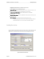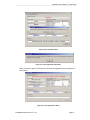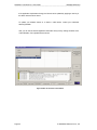
1
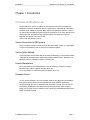
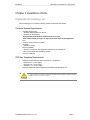
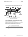
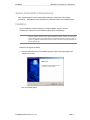
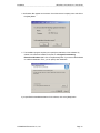
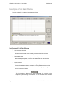
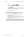
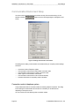
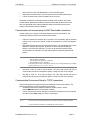
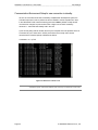
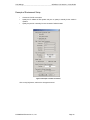
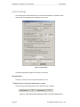
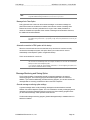
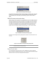
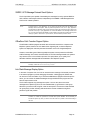
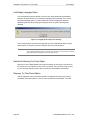
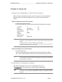
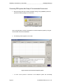
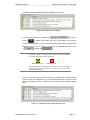
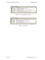
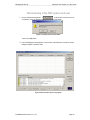
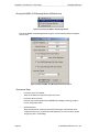
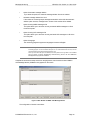
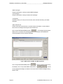
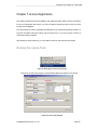
OfficeServ Link
User Guide
Version 2.1
June 2005
OfficeServ Link
Version 2.1
User Guide
This manual should be read before the installation
and operation of the OfficeServ Link Software.
COPYRIGHT
This manual is proprietary to SAMSUNG Electronics Co. Ltd. and is protected by copyright.
No information contained herein may be copied, translated, transcribed or duplicated for any
commercial purposes or disclosed to third parties in any form without the prior written consent of
SAMSUNG Electronics Co. Ltd.
TRADEMARKS
Samsung and
are trademarks of Samsung Electronics Co., Ltd.
OfficeServ Link is registered trademark of SAMSUNG.
Product names mentioned in this document may be trademarks and/or registered trademarks of
their respective companies.
Page ii
© SAMSUNG Electronics Co., Ltd
Preface
OfficeServ Link Version 2.1 User Guide
--------------------------------------------------------------------------------------------------------------------------------------------------------------------
Preface
About This Manual
This manual is a user’s guide for the OfficeServ Link application; this is a Computer
Telephony Integration (CTI) program which allows Samsung OfficeServ and iDCS telephone
systems to interact with one or more Computers connected to a Network.
This manual describes the main function, installation, optional features, and examples of
usage of the OfficeServ EasySet application.
This manual includes the phased description of program from the fundamental
understanding to the processes that shall be performed for the use of OfficeServ Link. The
layout of this manual is also useful for users to select and read only the chapters that
currently concern them. However, before using the OfficeServ Link, users need to be familiar
with this manual. Keep the notices of this manual in mind before installing or using the
programs.
If you have any question or problem while using the programs of OfficeServ Link, contact an
Authorized Samsung Reseller.
Conventions
The followings are symbols used in this manual. You have to be familiar with this information
along with these symbols to use the OfficeServ Link safely in an appropriate way.
Indicate a potentially hazardous situation which if not avoided, may result in
minor or moderate injury. It may also be used to alert against unsafe practices.
© SAMSUNG Electronics Co., Ltd.
Page iii
OfficeServ Link Version 2.1 User Guide
Preface
--------------------------------------------------------------------------------------------------------------------------------------------------------------------
(This page left blank intentionally.)
Page iv
© SAMSUNG Electronics Co., Ltd
Table Of Contents
OfficeServ Link Version 2.1 User Guide
--------------------------------------------------------------------------------------------------------------------------------------------------------------------
Table of contents
Preface iii
About This Manual .................................................................................................................iii
Conventions ...........................................................................................................................iii
Table of contents ............................................................................................................ v
Chapter 1 Introduction ................................................................................................... 7
Overview of OfficeServ Link...................................................................................................7
Various Connections to PBX systems.................................................................................7
Various Option Settings ......................................................................................................7
License Management .........................................................................................................7
Evaluation Period................................................................................................................7
Chapter 2 Installation of Link......................................................................................... 9
Preparation for installing Link .................................................................................................9
Computer System Requirements........................................................................................9
DCS Key Telephone Requirements ....................................................................................9
Configuration Environment...................................................................................................10
System Administration Requirements .................................................................................. 11
Installation ............................................................................................................................ 11
Post Installation ....................................................................................................................16
Checking the registered program group ........................................................................... 16
Installing the Link License................................................................................................. 16
Chapter 3 OfficeServ Link Settings ............................................................................. 17
Executing OfficeServ Link ....................................................................................................17
Description of Link Main Window.........................................................................................18
Configuration of Link Main Window .................................................................................. 18
Communication Environment Setup ....................................................................................20
Connection mode to telephone system ............................................................................ 20
Communication environment setup for SIM / Serial cable connections............................ 21
Communication Environment Setup for TCP/IP connections............................................ 21
Communication Environment Setup for user connection in standby ................................ 22
Example of Environment Setup ........................................................................................ 23
Option Settings.....................................................................................................................24
Normal option ................................................................................................................... 24
Message Monitoring and Saving Option ........................................................................... 25
SMDR / UCD Transmition Options.................................................................................... 27
OfficeServ Call+ Function Support Option........................................................................ 27
Link State Message Display Option .................................................................................. 27
Link Display Language Option.......................................................................................... 28
Switch Link Recovery Try Count Option ........................................................................... 28
Recovery Try Time Period Option..................................................................................... 28
© SAMSUNG Electronics Co., Ltd.
Page v
OfficeServ Link Version 2.1 User Guide
Table Of Contents
--------------------------------------------------------------------------------------------------------------------------------------------------------------------
Chapter 4 Using Link.................................................................................................... 31
Connecting to a telephone system ...................................................................................... 31
Connecting PBX system after Setup of Communication Environment..............................32
Disconnecting to the PBX system and user ........................................................................ 35
Chapter 5 Link Operating State View........................................................................... 36
Viewing Link state in Default mode ..................................................................................... 36
Chapter 6 Message Monitoring.................................................................................... 38
Call processing message monitoring program.................................................................... 38
SMDR / UCD Message Monitoring Program ...................................................................... 41
Installing Monitoring Program on other Computer............................................................... 46
Chapter 7 License Registration ................................................................................... 49
Running the License Tools .................................................................................................. 49
Installing the License ........................................................................................................... 50
Page vi
© SAMSUNG Electronics Co., Ltd
Introduction
OfficeServ Link Version 2.1 User Guide
--------------------------------------------------------------------------------------------------------------------------------------------------------------------
Chapter 1 Introduction
Overview of OfficeServ Link
The OfficeServ Link version 2.1(called Link) is a software product that sits between CTI
applications, (based on the Microsoft TAPI 2.x specifications), and Samsung’s OfficeServ
and iDCS range of telephone systems. Many different CTI applications based on TAPI 2.x
can interact with the telephone system through the intervention of Link. Also, all kinds of call
processing events generated from the telephone system are transferred to each CTI
application through the intervention of Link.
The Link has the following functions:
Various Connections to PBX systems
The Link supports various connections such as SIM, Direct Serial, TCP/IP, etc., depending
on system requirements in order to connect to the telephone system.
Various Option Settings
The Link provides various options that can be easily set depending on the operational states
- message-processed state view, SMDR/UCD message-related functions, OfficeServ Call,
OfficeServ Call Plus, OfficeServ Operator Processing, etc.
License Management
The Link provides a license management function for Samsung CTI Products including:
OfficeServ Call / CallPlus, Operator, EasySet, News etc.
To use any software, a valid license has to be installed on the Link.
Evaluation Period
You can use the OfficeServ Link in an evaluation mode for thirty days from first installation.
During this evaluation period, the Link application and other OfficeServ applications
connected through the Link, e.g. OfficeServ Call, will function correctly. The Link must be
registered by the application of a valid license key during this period, failure to apply a
license key will result in the non operation of the Link and any associated applications at the
end of the evaluation period.
© SAMSUNG Electronics Co., Ltd.
Page 7
OfficeServ Link Version 2.1 User Guide
Introduction
--------------------------------------------------------------------------------------------------------------------------------------------------------------------
(This page left blank intentionally.)
Page 8
© SAMSUNG Electronics Co., Ltd
Installation
OfficeServ Link Version 2.1 User Guide
--------------------------------------------------------------------------------------------------------------------------------------------------------------------
Chapter 2 Installation of Link
Preparation for installing Link
Before installing the Link software, following system requirements are needed.
Computer System Requirements
y
−
−
y
y
−
y
−
y
Operating System (OS)
Windows 2000 Professional / Server
Windows XP Professional
Recommended OS: Windows 2000 Professional or later
Note: Administrator privileges are required to install and run this application
CPU
Intel P4 1GHz (minimum) or faster
Hard Disk
500 MB or greater
Memory Capability
Minimum or more than the specification required for the installed OS
Memory Recommended: 256 MB or greater
LAN card, COM port
DCS Key Telephone Requirements
y
−
−
−
y
Telephone system software version required for Link Operation
iDCS 500: Ver. 1.33 or higher
DCS 100: Ver. 1.33 or higher
OfficeServ : Ver. 2.13 or higher
Other Key telephone systems capable of interworking with OfficeServ Link
In order to check if your telephone system has the latest version capable of supporting the Link,
contact your Authorised Samsung Reseller.
© SAMSUNG Electronics Co., Ltd.
Page 9
OfficeServ Link Version 2.1 User Guide
Installation
--------------------------------------------------------------------------------------------------------------------------------------------------------------------
Configuration Environment
The following figure shows the connections between the Link-installed computer and the
DCS Key telephone system, and relations among the CTI applications-installed computers.
95/98/ME/NT/2000/XP
NT / 2000 / XP
Any PC
OfficeServ Call
OfficeServ Operator
OpenTSP
3rd Party
CTI S/W
TCP / IP
OfficeServ
Link
ARC
Agent
OfficeServ Link Installed Computer
OpenTSP
EasySet
Server
(Web Server)
ARC Server
OfficeServ
ACD Server
DCS Key Telephony System
or
OfficeServ System
Open TSP
Installed Computer
Other
TAPi S/W
SIO, TCP/IP
EasySet
Client
EasySet
Client
ICC ICC ICC ACD
Agent AgentAgent
Agent
<< OfficeServ Link, Call, Operator, EasySet, OpenTSP Driver, ACD, 3rd Party S/W Configuration Diagram >>
Figure 2.1 Typical configuration diagram
As shown in the figure above, the Link supports SIO connections (SIM, Direct Serial
Connection) to the Telephone system, and the LAN connections of TCP/IP protocol. The
connections depend on the type of telephone system. Contact your Authorised Samsung
Reseller as to which connections your system supports.
In addition, the Link receives and manages a connection request from each user’s computer
through TCP/IP LAN, and transmits and receives messages generated between the
telephone system and the CTI applications that are running on users’ computers.
Note
Link connections for each DCS Key telephone system
•
iDCS 500 / 100 / OfficeServ: Supports Serial / LAN connections.
Note User’s CTI applications connected to the Link shall be based on Tapi 2.x. All CTI
Application that want to connect the DCS Key telephone system have to use the
OpenTSP Driver. The OpenTSP Driver is the Tapi 2.x compatible Telephony Service Provider for
rd
3 party Tapi compatible CTI Software.
Page 10
© SAMSUNG Electronics Co., Ltd
Installation
OfficeServ Link Version 2.1 User Guide
--------------------------------------------------------------------------------------------------------------------------------------------------------------------
System Administration Requirements
Users must be logged on with an Administrator privileges to install and run this program
successfully. Administrators have complete and unrestricted access to the computer/domain.
Installation
The Link installation process is provided in a single installation program. Execute
LinkSetup.exe, and then the Link installation program will run automatically.
Note
You have to install the Link program to use the CTI applications of the OfficeServ or iDCS
telephone systems. OfficeServ Call / CallPlus, OfficeServ Operator, EasySet, and Internet Call
Center Package, which are programs using the CTI application functions of DCS Key telephone
system, may utilize the switching function through all the Link. Before using those programs, you
have to install the Link.
Install the Link program as follows:
1. Execute LinkSetup.exe, the Link installation program, and the following dialog box will
appear on the screen.
Click on the [Next] button.
© SAMSUNG Electronics Co., Ltd.
Page 11
OfficeServ Link Version 2.1 User Guide
Installation
--------------------------------------------------------------------------------------------------------------------------------------------------------------------
2. License Agreement dialog box appears on the screen. Read the text of License
Agreement, and click on the [Next] button if you agree to its contents. If you do not agree,
the Link installation program exits automatically.
3. User and Company Registration box appears on the screen. Check the valid the user and
company name and click on the [Next] button.
Page 12
© SAMSUNG Electronics Co., Ltd
Installation
OfficeServ Link Version 2.1 User Guide
--------------------------------------------------------------------------------------------------------------------------------------------------------------------
4. Confirmation Box appears on the screen. Check the user and company name and click on
the [Next] Button.
5. The installation program requires you to specify the destination of Link software. By
default, Link software is installed on the path of “C:\Program Files\Samsung
Electronics\OfficeServ Link.” Click on the [Browser] button if you want to install software
on a different destination. Then, you can specify other destination.
If you specified the installed destination of Link software, click on the [Next] button.
© SAMSUNG Electronics Co., Ltd.
Page 13
OfficeServ Link Version 2.1 User Guide
Installation
--------------------------------------------------------------------------------------------------------------------------------------------------------------------
6. The installation program requires you to register the group name of Link programs. By
default, the installation program registers “OfficeServ Link“ as the group name. Click on
the [Next] button.
7. The installation program requires you to specify the computer’s Windows OS that you will
install Link software in. Choose the Windows OS to install, and click on the [Next] button.
(We recommend that you choose the OS coincided with that of computer – destination of
software installation.)
8. The Link software supports two language modes: Korean and English. The text included
in Link software is displayed depending on the mode specified in this dialog box. The
language mode can be changed after installation if required. Choose a mode and click
on the [Next] button.
Page 14
© SAMSUNG Electronics Co., Ltd
Installation
OfficeServ Link Version 2.1 User Guide
--------------------------------------------------------------------------------------------------------------------------------------------------------------------
9. The installation program asks if you want Link to run automatically at the time of system
booting. It you want, click on the [Yes] button. Then, the program will link you to the
Startup folder.
10. Installation has successfully completed. Click on the [Finish] button, then the installation
program exits.
© SAMSUNG Electronics Co., Ltd.
Page 15
OfficeServ Link Version 2.1 User Guide
Installation
--------------------------------------------------------------------------------------------------------------------------------------------------------------------
Post Installation
When Link software has successfully completed, you have to ensure that the following
programs have installed on the computer.
Checking the registered program group
y
y
y
y
Link: Executable program of Link
License Tools : License Registration Tools
Switch Message Monitor: Message monitoring program between PBX system and Link
SMDR-UCD Message Monitor: SMDR-UCD message monitoring program
Note
For further the details of each program, see Chapter 3.
Installing the Link License.
Before the Link Application can be configured and used, it must be licensed.
The License procedure is described in Chapter 7.
You can use the OfficeServ Link in an evaluation mode for thirty days from first installation.
During this evaluation period, the Link application and other OfficeServ applications connected
through the Link, e.g. OfficeServ Call, will function correctly. The Link must be registered by the
application of a valid license key during this period, failure to apply a license key will result in the
non operation of the Link and any associated applications at the end of the evaluation period.
Page 16
© SAMSUNG Electronics Co., Ltd
Link Settings
OfficeServ Link Version 2.1 User Guide
--------------------------------------------------------------------------------------------------------------------------------------------------------------------
Chapter 3 OfficeServ Link Settings
Executing OfficeServ Link
Proceed to [Start] -> [Program] -> [OfficeServ Link] and choose Link. Then, Link program will
run. As soon as Link starts running, the following dialog box appears on the screen.
Figure 3.1 Main Window of Link
Note
If you have set up the Link to link to the Startup folder when installing the Link (when you click on
YES), the system booting runs the Link automatically.
© SAMSUNG Electronics Co., Ltd.
Page 17
OfficeServ Link Version 2.1 User Guide
Link Settings
--------------------------------------------------------------------------------------------------------------------------------------------------------------------
Description of Link Main Window
The main window of Link consists of several panes as follows:
Figure 3.3 Main Window of Link
Configuration of Link Main Window
y
User connection state pane
This area indicates information of each user who has connected to the Link software.
This pane shows the state of users currently connected to the Link in real time.
y
State message pane
This area indicates the current working state of Link. This pane shows connection
state to the telephone system, connection state to user, and error description if an
error occurs.
y
Function buttons
These buttons are related to the environment setting and operation of Link software.
The use of these buttons depends on whether or not the pertinent functions can be
used. You can enable and disable these function buttons during setup. The types of
function buttons are as follows:
−
Page 18
Set Communication Environment (
)
This function button allows you to set the parameters for connection to the
telephone system including the IP address and also define the user connection
© SAMSUNG Electronics Co., Ltd
Link Settings
OfficeServ Link Version 2.1 User Guide
--------------------------------------------------------------------------------------------------------------------------------------------------------------------
ports required.
−
Connect / Disconnect (
/
)
this function button is a toggle button and allows you to connect to or disconnect
from the telephone system.
−
Set Options (
)
)
this function button allows you to set up various options within the Link software.
With this button, you can set whether or not to use the user management function,
the message monitoring function, and language mode, etc.
y Link Status bar information
Figure 3.3 Status Bar
−
−
−
−
Note
The main window of Link has a status bars showing the current working status.
The indications are as follows:
Connection mode: Indicates the currently set connection mode.
Connection state: Indicates the connection state between telephone system and Link.
The number of used License: Indicates the number of the currently connected
software with the allowed license.
The number of Total License: Indicates the number of total license.
The description of Link state indications is included in that of option settings and function buttons.
© SAMSUNG Electronics Co., Ltd.
Page 19
OfficeServ Link Version 2.1 User Guide
Link Settings
--------------------------------------------------------------------------------------------------------------------------------------------------------------------
Communication Environment Setup
You have to set up communication environment correctly for the normal working of Link
software. Choose【
】button, then the following dialog box will appear on the
screen.
Figure 3.4 Setting communication environment
The dialog box for setting communication environment allows you to specify various settings
as follows:
y
y
y
y
y
y
Connection mode to Telephone system
Communication environment for SIM / Serial connection mode
Communication environment for TCP/IP connection mode
Switch Type for communication environment
Communication environment for user connection standby
Password Information for requesting switch information
Connection mode to telephone system
Link provides three kinds of connection modes for Samsung telephone systems. The dialog
box for setting the communication environment of Link allows you to select entries
depending on the system in use.
You can choose one of the following three connection modes.
Page 20
© SAMSUNG Electronics Co., Ltd
Link Settings
OfficeServ Link Version 2.1 User Guide
--------------------------------------------------------------------------------------------------------------------------------------------------------------------
y
y
y
SIM connection mode: Uses SIM Module to connect the PBX system.
Serial Cable connection mode: Connects a serial cable to the PBX system directly.
TCP/IP connection mode: Uses LAN-based TCP/IP to connect
These three connections are basically divided into Serial communications and TCP/IP
communications. Because both methods need environment settings different from each
other, the appropriate communication parameter dialog box becomes active once the
primary communications method is selected.
Communication environment setup for SIM / Serial cable connections
This entry allows you to change environment settings for serial communications. The
environment settings for serial communications are as follows:
y
y
COM Port: Receives the COM port No. of computer. The Link software uses the specified
COM port No. to set up the channel of serial communications to connect the telephone
system.
Baud Rate: Receives the value of serial communications. Your specification of this value
depends on the baud rate of system. By default, the value is defined as 9600 bps.
However, as for iDCS 500 / OfficeServ, you have to use the primary speed of serial
communications as 19200 bps. This value shall conform to the primary speed of PBX
system.
Note
Primary speed of serial communications for each telephone system
• DCS 180: SIM Type, 9600 BPS
• SDX COMPACT: SIM / Serial Type, 19200 BPS
• iDCS 500/OfficrServ: Serial, 19200 BPS
Each system has a function of changing the baud rate. For the setting related with your installed
system, contact an Authorised Samsung Reseller.
y
Data Size: A value of 8 bits is used by default. This value shall coincide with that of
communication environment of telephone system. Usually, this value is not changed.
y
Stop Bits: A value of 1 bit is used by default. This value shall coincide with that of
communication environment of telephone system. Usually, this value is not changed.
Communication Environment Setup for TCP/IP connections
Some Samsung telephone systems support the LAN-based TCP/IP communications. The
environment settings for TCP/IP connections are as follows:
y
IP address: Receives the IP address of telephone system working in TCP/IP.
(See the MMC 830 settings of Key telephone system.)
y
Port No.: Receives the port No. waiting for a connection request from the Link. By default,
this value is set to 5002. Usually, this value is not changed.
Note
TCP/IP connection is the preferred method of connection for iDCS and OfficeServ Systems.
The other methods are retained for compatibility with previous systems.
© SAMSUNG Electronics Co., Ltd.
Page 21
OfficeServ Link Version 2.1 User Guide
Link Settings
--------------------------------------------------------------------------------------------------------------------------------------------------------------------
Communication Environment Setup for user connection in standby
As soon as connections have been successfully completed with the telephone system, the
Link starts a process in order to perform the service needed to receive requests from users.
In the LAN-based TCP/IP case this listening port is set to 6000 by default. Usually this will
not need to be changed, but port numbers 1024 or higher can be used if necessary.
Values of 0 ~ 1023 have been already built in the Link.
A port currently being used for another service by the computer cannot be specified. There is
a command for you to check which TCP/IP port numbers are currently used. Use the
command at the command prompt of Windows as follows:
c:\>Netstat -a -e -n -p TCP
Figure 3.5 Status View of Ports in Use
Note
Page 22
The setting of communication environment can be done only in the offline status between Link
and telephone system. Online state (Disabled) does not allow you to activate this function button.
© SAMSUNG Electronics Co., Ltd
Link Settings
OfficeServ Link Version 2.1 User Guide
--------------------------------------------------------------------------------------------------------------------------------------------------------------------
Example of Environment Setup
y
y
y
Choose the TCP/IP connections.
Specify the IP address of PBX system and port no. (5002) in standby for the entries in
question.
Specify the port No. in standby for user connection. Default is 6000.
Figure 3.6 Example of TCP/IP connections
Click on the [Yes] button, and then the changes are saved.
© SAMSUNG Electronics Co., Ltd.
Page 23
OfficeServ Link Version 2.1 User Guide
Link Settings
--------------------------------------------------------------------------------------------------------------------------------------------------------------------
Option Settings
The Link has option entries that allow you to control various operations. Choose the option
button and the following dialog box will appear on the screen.
Figure 3.7 Options Menu
The following description applies to the function of each entry.
Normal option
This option is used to control the operational features of Link.
Restriction for the currently connected users in number
This value will be set automatically when the valid license key is installed.
Figure 3.8 Status indication bar showing the number of currently installed licenses
Page 24
© SAMSUNG Electronics Co., Ltd
Link Settings
OfficeServ Link Version 2.1 User Guide
--------------------------------------------------------------------------------------------------------------------------------------------------------------------
Note
The Link will not accept any client connection requests without a valid license.
To get the valid license key, Contact the Authorised Samsung Reseller.
Message Auto Clear Option.
During Operation the Link shows various status messages on the status message bar
placed at the bottom of the Window. If enabled, the maximum number of message lines
retained can be set in this field. (selected from a range of 100 to 9999). If disabled, a
maximum of 9999 lines is specified. If the number of message lines exceeds the maximum,
the additional lines will be deleted.
Note
We recommend that you enable the message Auto clear option, and set the number of lines to a
low setting during normal use. If you specify a high value, the performance of Link may be
affected.
Automatic connection to PBX system at Link startup
When the communication environment has been set up and the Link has been normally
connected to the telephone system, this option allows you to make the Link connect
automatically to the telephone system on application startup.
This is recommended for normal use.
Note
When the Link has been linked to Startup folder during installation, and this option is selected,
the Link will run automatically when the computer is started, and the Link will automatically
attempt to connect to the telephone system.
If you need to change the communication environment, or are reconfiguring the system, this
option should be deactivated before restarting.
Message Monitoring and Saving Option
The Link has the ability of transmitting internally processed messages to an external
monitoring program. This monitoring program is installed together with Link software. In
addition, if you install the additionally provided monitoring program, you can also monitor the
messages that are currently processed via LAN on the other computers.
General message monitoring option settings
A general message means a call-processing message that is transmitted and received
between Link and the telephone system. The Link transmits the currently exchanged general
message to the general message-monitoring program, and the monitoring program shows
you the received message. It also provides a Save function.
The General message monitoring program, [Switch Message Monitor] is installed when Link
software is installed.
© SAMSUNG Electronics Co., Ltd.
Page 25
OfficeServ Link Version 2.1 User Guide
Link Settings
--------------------------------------------------------------------------------------------------------------------------------------------------------------------
Figure 3.9 General message monitoring program
For connection to the general message monitoring program, Port Number ‘6001’ is specified
by default. You can access to the Link by using the IP address of computer that Link runs
and its specified port No, when setting up the monitoring program. A value of ‘6001’ is
default.
SMDR/ UCD message monitoring option settings
SMDR message or UCD message can be transmitted to the Link from the telephone system,
according to the settings of CTI option. The SMDR / UCD message can provide charging or
UCD group information through an additional program (not supplied). The Link can monitor
such SMDR / UCD messages in the form of that is transmitted from the telephone system.
To monitor such messages, the Link provides the SMDR / UCD message monitoring
program similar to the general message-monitoring program. It is set to ‘6002’ by default.
Figure 3.10 SMDR / UCD message monitoring program
Information of the message monitoring setting state is indicated on the main window of Link
as follows:
Figure 3.11 Link indicator for message monitoring setting status
Note
The detailed description of Switch Message Monitor and SMDR / UCD Message Monitor program
is included in the section of message monitoring.
Password Protection Option
The Link protects the anonymous access of a CTI or SMDR port by using the password.
Before connecting the message monitoring port, each monitor program should send the valid
password to the Link. the link can change the password anytime.
Page 26
© SAMSUNG Electronics Co., Ltd
Link Settings
OfficeServ Link Version 2.1 User Guide
--------------------------------------------------------------------------------------------------------------------------------------------------------------------
SMDR / UCD Message Exteranl Send Options
The Link provides a port capable of transmitting two messages for use by optional SMDR or
UCD collection and analysis software, independently of the SMDR / UCD Message Monitor.
This Port No. is 6003 by default.
Note
rd
According to the 3 party application, you can change the access method for the SMDR / UCD
rd
Message external send option. With the password protection mode, the 3 party application
should follow the password check protocol before accessing the external send port. Without the
rd
protection mode, any 3 party application can access the SMDR / UCD message external send
port. You have to remember that SMDR or UCD message can include some internal security data
relating to system or each device. To protect them, use the Password protection mode..
OfficeServ Call+ Function Support Option
The OfficeServ CallPlus program transmits caller information saved in the computer to the
telephone system, based on the CLI details of the originating call, so that the telephone
system can display this and other pertinent information on the LCD of digital telephone.
However, some older types of Samsung telephone system cannot process the OfficeServ
CallPlus message. In this case, the transmission of Link Plus message toward such systems
may cause an error in the connection process. This option allows you to specify if the
OfficeServ CallPlus message shall be transmitted to the Telephone system.
Note
To check whether or not your Telephone system supports the function of OfficeServ Call Plus
message, contract an Authorised Samsung Reseller.
Link State Message Display Option
In the case of a system error, the Link can transmit a trace message of its internal processes
to an external program to provide debugging information. A debugging tool, DBView.exe,
can be found in the Tools folder. If you execute the DBView.exe program while this option is
active, you can monitor the detailed messages through the DBView.exe program and can
save the output result in a file.
The Link also supports a log message save option. Link can save the current event
messages into a specific log file on the Link installed folder. (Log File Name: LinkLog.txt).
Whenever you want to make a log file, check the save option. The amount of data collected
can grow quickly so after collecting data remember to rename or delete that log file to
prevent a log file size problem.
Note
The status message output options have a significant effect on the performance of Link program.
Therefore, in normal use, operate the Link with these options disabled. We recommend you
activate this option only when you need to trace the cause of a problem or abnormal working in
the Link.
© SAMSUNG Electronics Co., Ltd.
Page 27
OfficeServ Link Version 2.1 User Guide
Link Settings
--------------------------------------------------------------------------------------------------------------------------------------------------------------------
Link Display Language Option
The Link supports Korean and English, and runs in the mode specified during installation.
However, this option allows you to change the language mode if necessary. If you want to
change the language mode, you have to restart the Link after changing the mode and
deactivating the Link. When changing the language mode, you get the following alarm
message.
Figure 3.12 Language mode change alarm message.
Click on the [OK] button to save the changes after you have completed the setting of all the
options above. If you want to cancel the changes, click on the [Cancel] button.
Note
The Link installation has a default for each entry. However some of the defaults may not be correct
for the particular telephone system or computer used. Therefore, we recommend you check the
settings depending on the telephone system and Computer used.
Switch Link Recovery Try Count Option
When the CTI link is failed between the Link and the Switch, the link will try to recover the cti
link until the retry count value is 0 or the cti link is recovered. The initial value of this recovery
try count is 30.(the minimum value). User can select one value between 30 and 9999.
Recovery Try Time Period Option
User can adjust the recover interval time period by changing the recovery try time period.
The default value of this option is 1 minute. User can select one value between 1 and 255.
Page 28
© SAMSUNG Electronics Co., Ltd
Link Settings
OfficeServ Link Version 2.1 User Guide
--------------------------------------------------------------------------------------------------------------------------------------------------------------------
(This page left blank intentionally.)
© SAMSUNG Electronics Co., Ltd.
Page 29
Message Monitoring
OfficeServ Link Version 2.1 User Guide
--------------------------------------------------------------------------------------------------------------------------------------------------------------------
Chapter 4 Using Link
Check the configuration of the Phone System.
Before connecting to the telephone system, you have to set up the connection parameters
within the system; the method used depends on the connection mode. (SIM, Serial, or
TCP/IP).
Telephone settings for a serial Link connection
y
For SIM or Serial connection mode,
Be sure that the MMC 804 settings of DCS Key telephone PBX system are as follows:
Sys IOPort
Service
BAUD RATE
CHAR LENGTH
PARITY
STOP BIT
RETRY COUNT
WAIT TIME
Note
2
CTI-SMDR
9600 or 19200
8
NONE
1
5
03000 msec.
* (1)
* (2)
* (3)
The “*” means that you can change the value as needed.
The change of (1) entry depends on the number of ports provided by Samsung Key telephone
system.
The (2) entry can have one of CTI, CTI-SMDR, CTI/UCD, and CTI/S/U.
The baud rate of (3) entry depends on that of Samsung Key telephone system. The baud rate of
Link shall be specified based on the value of (3) entry.
Telephone settings for an IP Link connection
y
For TCP/IP connections,
Be sure that the IP address of the telephone system has been specified in the MMC
830. This IP address shall be the same as in the communication environment of Link.
Note
Some of the DCS Key telephone systems that support TCP/IP connections cannot transfer SMCR
/ UCD information to the TCP/IP port. When interworking with these systems, the Link does not
transfer the SMDR / UCD message.
Connecting to a telephone system
After setting the parameters above, click on the [CONNECT] button of Link
【
】, and proceed to the connection process of PBX system.
Note
In you intend to use the Link in the user management mode, add the user information before
proceeding to the connection process of PBX system. For details of user management, see later in
this chapter.
© SAMSUNG Electronics Co., Ltd.
Page 31
OfficeServ Link Version 2.1 User Guide
Message Monitoring
--------------------------------------------------------------------------------------------------------------------------------------------------------------------
Connecting PBX system after Setup of Communication Environment
1. After all the steps have been normally completed, clicking on the [CONNECT] button will
generate the following dialog box on the screen.
Figure 4.1 Click on the [CONNECT] button
Click on the [OK] button; and the Link attempts to connect the telephone system by using the
communication environment established.
2. The following window appears on the screen.
Figure 4.2 Process of connection to telephone system
y
As soon as the process of connection to the telephone system has successfully
Page 32
© SAMSUNG Electronics Co., Ltd
Message Monitoring
OfficeServ Link Version 2.1 User Guide
--------------------------------------------------------------------------------------------------------------------------------------------------------------------
completed, the following state message pane appears on the screen.
Figure 4.3 Connection success message
y
, and the AVI
The connection state of Link is indicated as
picture【
】 rotates in the bottom right corner of the window. This means the
currently connected state is normal. The static AVI picture means that the connection has
stopped running or there is an error. At this time, the [CONNECT] button of Link
【
Note
】changes into
】.
If there is an error in the connection between Link and PBX system, error
information is displayed on the message pane. Information of each state displayed
on the state message pane has its icon respectively.
GeneralMessage.ico
ErrorMessage.ico
The General Message Icon means that the Link notifies a user of general message,
and the Error Message Icon means that the Link notifies a user of error message
generated while the Link runs.
y
If an error occurs during the connection process, the Link performs an automatic recovery
process until the error disappears (or up to the internally limited time). If the Link cannot
perform the automatic recovery, it notifies users of the error through the status message
pane.
Figure 4.4 Automatic recovery message after error event
© SAMSUNG Electronics Co., Ltd.
Page 33
OfficeServ Link Version 2.1 User Guide
Message Monitoring
--------------------------------------------------------------------------------------------------------------------------------------------------------------------
Figure 4.5 1st recovery try failed and wait 1 minute
Figure 4.6 recovery success
Page 34
© SAMSUNG Electronics Co., Ltd
Message Monitoring
OfficeServ Link Version 2.1 User Guide
--------------------------------------------------------------------------------------------------------------------------------------------------------------------
Disconnecting to the PBX system and user
1. Click on the [Disconnect] button 【
】 to disconnect a link from the Link,
if necessary. Then, the following dialog box appears on the screen
Figure 4.7 Selection of Disconnect button
Click on the [OK] button.
2. The Link displays the following pane on the screen, and finishes the connection with the
telephone system and all the users.
Figure 4.8 Disconnection process in progress
© SAMSUNG Electronics Co., Ltd.
Page 35
OfficeServ Link Version 2.1 User Guide
Message Monitoring
--------------------------------------------------------------------------------------------------------------------------------------------------------------------
Successful disconnection changes the connection state of Link and indicates it
as
, and changes the [Disconnect] button
from【
】to 【
】.
Chapter 5 Link Operating State View
When the communications environment setup, telephone system linkage, user management,
and device management have been completed for the Link and the Link is running normally,
each user can access to the Link as needed.
This chapter describes the operation state for Link in normal service.
Viewing Link state in Default mode
Figure 5.1 Link running in default mode
Figure 5.7 shows the normal working of Link running in default mode. While the Link is
running in this mode, the user connection state window shows the following information:
y
IP address
Indicates the IP address of connected user computer.
y
Port No.
Indicates the port No. used for TCP/IP communication with the Link. The port No. of
Link corresponds to that set in the communication environment. Default is 6000.
Page 36
© SAMSUNG Electronics Co., Ltd
Message Monitoring
OfficeServ Link Version 2.1 User Guide
--------------------------------------------------------------------------------------------------------------------------------------------------------------------
y
User type
All the users connected to the Link running in inactive mode of user management are
indicated as “User in inactive management”.
y
y
Connection state
Indicates the connection state. When it runs correctly, “Connected” is indicated.
y
In case that a user is currently connected
Figure 5.2 User-connected Link
Figure 5.3 User connection status window in the default mode
© SAMSUNG Electronics Co., Ltd.
Page 37
OfficeServ Link Version 2.1 User Guide
Message Monitoring
--------------------------------------------------------------------------------------------------------------------------------------------------------------------
Chapter 6 Message Monitoring
Sometimes, you need to monitor various message processing procedures performed by the
Link. When the Link is installed, the message-monitoring program is installed.
The Link provides the program capable of monitoring the following messages.
y
Call processing messages transmitted and received between the telephone system and
user applications
y
SMDR / UCD message provided by DCS Key telephone system
To monitor such messages, the Link provides three kinds of monitoring programs.
y
Call processing message monitoring program: SCMonitor.
e.g., placed in [\Program Files\Samsung Electronics\Link].
y
SMDR / UCD message monitoring program: SUMonitor.exe
e.g., placed in [\Program Files\Samsung Electronics\Link].
Call processing message monitoring program
Many kinds of messages are transmitted and received between the telephone system, Link,
and other applications such as OfficeServ Call, OfficeServ CallPlus, OfficeServ Operator,
EasySet as well as TAPI 2.x Standard API-based CTI applications. The call processing
message monitoring program allows you to monitor the call processing messages currently
received and processed by Link, regardless of program location.
Running the Switch Message Monitor (SCMonitor.exe)
Figure 6.1 Running the Switch Message Monitor Program
Execute the Switch Message Monitor program (SCMonitor.exe), and the following dialog box
will appear on the screen.
Page 38
© SAMSUNG Electronics Co., Ltd
Message Monitoring
OfficeServ Link Version 2.1 User Guide
--------------------------------------------------------------------------------------------------------------------------------------------------------------------
Figure 6.2 Environment Setup of Switch Message Monitor Program
Environment Setup
y
Connection server’s IP address
Enter the IP address of computer that the Link runs on.
y
Connection server’s port No.
Enter the port number specified as the general message monitoring port No. in the
Link configuration menu.
y
Access Password.
Enter the password for monitoring the cti message. This password will be configured
by the link. it you enter the invalid password, you can’t connect to the link and get any
cti message.
y
Option of automatic message deletion
If you select this option, the automatic message deletion function is enabled.
y
Automatic message deletion line count
If the number of monitoring output messages exceeds this value while the automatic
deletion option is active, message lines in excess of this number will be deleted.
y
Option of saving message to file
This option allows you to save the currently monitored messages to a file in the local
computer.
y
Option of language
The monitoring programs support two languages: Korean and English.
© SAMSUNG Electronics Co., Ltd.
Page 39
OfficeServ Link Version 2.1 User Guide
Message Monitoring
--------------------------------------------------------------------------------------------------------------------------------------------------------------------
Note
The monitoring environment setup window appears only on the first startup of the monitoring
program. For the IP address and port No. for communication with the Link, see the values
entered in the environment setup entries of Link.
When you have save file option is activated, the log file is placed in the log folder on the installed
path. (by default, C:\Program Files\Samsung Electronics\OfficeServ Link”)) that the Link and Switch
Message Monitor program were installed in.
Click on the [OK] button when the environment setup has completed, then the following main
window of Switch Message Monitor (SCMonitor.exe) appears on the screen.
Figure 6.3 Main window of Switch Message Monitor
The configuration of the main window is as follows:
Messages
Shows the T/x Rx call processing message received by the Link. The Tx/Rx call processing
messages are classified into those coming from the user applications to the telephone
system and those coming from the telephone system to user applications. The monitoring
program indicates this by using different Icons (Æ , Å)
Config button
This button allows you to set up the environment, start / terminate monitoring, and delete
messages.
Status indication bar
This bar shows the connected server, connection status, and whether or not the deletion /
save function of message monitoring has been activated, etc.
Click on the [START MONITORING] button【
】. The message monitoring starts
after the Link is connected. The following figure shows an example of the monitoring
program and some sample messages.
Page 40
© SAMSUNG Electronics Co., Ltd
Message Monitoring
OfficeServ Link Version 2.1 User Guide
--------------------------------------------------------------------------------------------------------------------------------------------------------------------
Figure 6.4 Monitoring program showing system messages
Click on the [STOP MONITORING] button [
Click on the [CLEAR VIEW] button [
] to stop monitoring.
] to delete the messages that are currently
displayed on the window. This function does not delete messages already saved to a file.
Note
The save file option appends the message to the end of the existing file until you change the file
name.
SMDR / UCD Message Monitoring Program
The telephone system can provide SMDR messages and UCD messages if required to
external applications for processing through an additional communications port. The SMDR /
UCD message monitoring program provides the ability of monitoring such SMDR / UCD
messages.
Note
For the Link to receive SMDR or UCD message from the telephone system, you have to set up the
MMC 804 function of the system to one of the following CTI / SMDR, CTI / UCD, CTI / S / U. The
purpose of this setup is to make it possible to transmit SMDR / UCD message to the Link, in the
form of a CTI event. Some Samsung telephone system may use the different MMC for this
information when configured for LAN communications. For more details, contact your Authorised
Samsung Reseller.
© SAMSUNG Electronics Co., Ltd.
Page 41
OfficeServ Link Version 2.1 User Guide
Message Monitoring
--------------------------------------------------------------------------------------------------------------------------------------------------------------------
Running the SMDR / UCD Message Monitor (SUMonitor.exe)
Figure 6.5 Executing the SMDR / UCD Message Monitor
Execute the SMDR / UCD Message Monitor Program, and the following dialog box appears
on the screen.
Figure 6.6 Setup of SMDR / UCD Message Monitor Environment
Environment Setup
y
Connection server’s IP address
Enter the IP address of computer that the Link runs on.
y
Connection server’s port No.
Enter the port number specified as the SMDR/UCD message monitoring port No. in
the Link configuration menu.
y
Access Password.
Enter the password for monitoring the smdr/ucdi message. This password will be
configured by the link. it you enter the invalid password, you can’t connect to the link
and get any smdr / ucd message.
Page 42
© SAMSUNG Electronics Co., Ltd
Message Monitoring
OfficeServ Link Version 2.1 User Guide
--------------------------------------------------------------------------------------------------------------------------------------------------------------------
y
Option of automatic message deletion
If you select this option, the automatic message deletion function is enabled.
y
Automatic message deletion line count
If the number of monitoring output messages exceeds this value while the automatic
deletion option is active, message lines in excess of this number will be deleted.
y
Option of saving SMDR message to file
This option allows you to save the currently monitored SMDR messages to a file in
the local computer.
y
Option of saving UCD message to file
This option allows you to save the currently monitored UCD messages to a file in the
local computer.
y
Option of language
The monitoring programs support two languages: Korean and English.
Note
The monitoring environment setup window appears only on the first startup of the SMDR/UCD
monitoring program. For the IP address and port No. for communication with the Link, see the
values entered in the environment setup entries of Link.
When you have save file option is activated, the file is placed in the log folder on the installed
path (by default, C:\Program Files\Samsung Electronics\Link”)) that the Link and SMDR/UCD
Message Monitor program were installed in.
Complete the environment setup and click on the [OK] button, then the main window of SMDR /
UCD Message Monitor (SUMonitor.exe) appears on the screen.
Figure 6.7 Main Window of SMDR / UCD Message Monitor
The configuration of window is as follows:
© SAMSUNG Electronics Co., Ltd.
Page 43
OfficeServ Link Version 2.1 User Guide
Message Monitoring
--------------------------------------------------------------------------------------------------------------------------------------------------------------------
SMDR messages
This pane indicates the currently monitored SMDR messages.
UCD messages
This pane indicates the currently monitored UCD messages.
Config button
This button allows you to set up the environment, start / terminate monitoring, and delete
messages.
Status indication bar
This bar shows the connected server, connection status, and whether or not the deletion /
save function of message monitoring has been activated, etc.
Click on the [START MONITORING] button【
】. The message monitoring starts
after the Link is connected. The following figure shows an example of the SMDR/UCD
monitoring program and some sample messages.
Figure 6.8 Main window of SMDR / UCD Message Monitor
Click on the [STOP MONITORING] button【
】, then the monitoring stops running
immediately. Click on the [CLEAR SMDR, UCD] buttons 【
,
】, and the
currently displayed messages are deleted. This function does not delete messages already
saved to a file.
Page 44
© SAMSUNG Electronics Co., Ltd
Message Monitoring
OfficeServ Link Version 2.1 User Guide
--------------------------------------------------------------------------------------------------------------------------------------------------------------------
Note
The save file option appends the message to the end of the existing file until you change the file
name.
© SAMSUNG Electronics Co., Ltd.
Page 45
OfficeServ Link Version 2.1 User Guide
Message Monitoring
--------------------------------------------------------------------------------------------------------------------------------------------------------------------
Installing Monitoring Program on other Computer
The installation of Switch Message Monitor program and SMDR / UCD Message Monitor
program is completed together with the installation of Link. Sometimes, however, you may
need to run the monitoring programs on another computer that the Link does not run on. To
this end, you can install and use the monitoring programs on this computer.
The monitoring program setup file is located in the “C:\Program Files\Samsung
Electronics\OfficeServ Link\Tools\MSGMonitor.exe”.
Page 46
© SAMSUNG Electronics Co., Ltd
Message Monitoring
OfficeServ Link Version 2.1 User Guide
--------------------------------------------------------------------------------------------------------------------------------------------------------------------
(This page left blank intentionally.)
© SAMSUNG Electronics Co., Ltd.
Page 47
OfficeServ Link Version 2.1 User Guide
--------------------------------------------------------------------------------------------------------------------------------------------------------------------
Chapter 7 License Registration
This chapter describes the license installation and update procedure with the license tools applet.
To use a CTI application with the link, you have to install the valid license key into the Link within
30 days of first installation..
The valid license key will be generated and distributed by an Authorised Samsung Reseller. To
get more information about the license and the license key for your own purpose, contact an
Authorized Samsung Reseller.
After getting the valid license key, you can install it into the link with license tools program.
Running the License Tools
Figure 8.1 Running the License Tools Program
Execute the License Tools program, and the following dialog box appears on the screen.
Figure 8.2 License Tools Window
© SAMSUNG Electronics Co., Ltd.
Page 49
OfficeServ Link Version 2.1 User Guide
Message Monitoring
--------------------------------------------------------------------------------------------------------------------------------------------------------------------
▪
Registered License displays the installed license key string.
▪
License Type shows the installed license’s type.
▪
Allowed MAC Type shows if the MAC address from the Telephone system or the
computer is to be used. This type is determined by the license key
▪
License Allowed MAC Address shows the MAC Address to be allowed
by the license key
▪
Allowed Software Status shows the applications that have been licensed by the
key and can be used.
▪
MAC Information Shows the MAC Addresses detected by the Link
-
Computer MAC Address is the current computer system MAC Address.
-
Switch MAC Address is the current switch system MAC Address.
Installing the License
Copy and Paste the valid license key string into “Enter License” of Add License and click
register button. If the entered license is valid, that license will be registered into the link.
Figure 8.3 Paste the valid license key
Page 50
© SAMSUNG Electronics Co., Ltd
OfficeServ Link Version 2.1 User Guide
--------------------------------------------------------------------------------------------------------------------------------------------------------------------
Figure 8.4 Link Shutdown Check
Figure 8.5 License Registration Notification
When you click OK button, the license tool will show the registered license information as
shown below.
Figure 8.6 License Registration Status
© SAMSUNG Electronics Co., Ltd.
Page 51
OfficeServ Link Version 2.1 User Guide
Message Monitoring
--------------------------------------------------------------------------------------------------------------------------------------------------------------------
If the application requirements change, the license can be updated by applying a new key in
the same manner as show above.
To update your software license or to obtain a valid license, contact your Authorized
Samsung Reseller.
Also, you can see the license registration information at any time by clicking the about menu
of the OfficeServ Link’s System Menu as shown
Figure 8.8 How to check the License Status
Page 52
© SAMSUNG Electronics Co., Ltd
OfficeServ Link Version 2.1 User Guide
--------------------------------------------------------------------------------------------------------------------------------------------------------------------
(This page left blank intentionally.)
© SAMSUNG Electronics Co., Ltd.
Page 53
OfficeServ Link Version 2.1 User Guide
Message Monitoring
--------------------------------------------------------------------------------------------------------------------------------------------------------------------
Samsung OfficeServ Link
Ver. 2.1
User Guide
©2002 Samsung Electronics Co., Ltd
All rights reserved
Information in this document is proprietary to SAMSUNG
Electronics Co., Ltd
No information contained here may be copied, translated,
transcribed or duplicated by any from without the prior
written consent of SAMSUNG.
Information in this document is subject to change without
notice.
Visit us at
http://www.samsungnetwork.com
Page 54
© SAMSUNG Electronics Co., Ltd