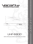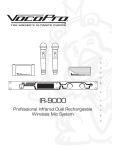
1
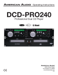
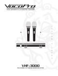
THE SINGER'S ULTIMATE CHOICE
FEATURES:
• Dual CD/CD+G deck player with separate CD+G decoders
• Switchable NTSC/PAL video output
a
o
w
n
e
r
• Choose between Single Track or Continuous Play modes
m
• Rugged, rackmountable design for the professional KJ and
DJ
s
• Professional Shuttle Dial and Jog Wheel for precision
cueing and frame searching
'
• Loop function allows you to create segments for
continuous play on the fly
n
u
• +/- 12 Pitch Control that does not scramble lyrics when
adjusted
a
• Easy track programmability from the front panel
l
• Individual 12-step Digital Key Control for each deck
CDG-9000PRO
Professional Dual CD/CDG Player with Key Control
CDG-9000PRO
Professional Dual CD/CDG Player
with Key Control
CONTENTS
Safety Instructions ........................................................ 3
FCC Information ............................................................ 4
Welcome ...................................................................... 5
Listening for a Lifetime .................................................. 6
Before Getting Started .................................................. 7
Installing and Getting Connected ..................................... 8
Descriptions and Functions ........................................ 9-12
Operations ............................................................ 13-16
Specifications ............................................................. 17
2
Safety Instructions
8. Ventilation - The appliance should be situated so its
location does not interfere with its proper ventilation. For
example, the appliance should not be situated on a bed,
sofa, rug, or similar surface that may block the
ventilation slots.
CAUTION
RISK OF SHOCK
9. Heat - The appliance should be situated away from
heat sources such as radiators, heat registers,
stoves, or other appliances (including amplifiers)
that produce heat.
CAUTION: To reduce the risk of electric shock,
do not remove cover (or back). No userserviceable parts inside. Only refer servicing to
qualified service personnel.
10. Power Sources - The appliance should be
connected to a power supply only of the type described
in the operating instructions or as marked on the
appliance.
Explanation of Graphical Symbols
The lightning flash & arrowhead
symbol, within an equilateral triangle,
is intended to alert you to the
presence of danger.
11. Grounding or Polarization - Precautions should be
taken so that the grounding or polarization means of
an appliance is not defeated.
12. Power-Cord Protection - Power-supply cords
should be routed so that they are not likely to be walked
on or pinched by items placed upon or against them,
paying particular attention to cords at plugs,
convenience receptacles, and the point where they exit
from the appliance.
The exclamation point within an
equilateral triangle is intended to alert
you to the presence of important
operating and servicing instructions.
WARNING
13. Cleaning - Unplug this unit from the wall outlet
before cleaning. Do not use liquid cleaners or
aerosol cleaners. Use a damp cloth for cleaning.
To reduce the risk of fire or electric shock, do
not expose this unit to rain or moisture.
14. Power lines - An outdoor antenna should be
located away from power lines.
1. Read Instructions - All the safety and operating
instructions should be read before the appliance is
operated.
15. Nonuse Periods - The power cord of the appliance
should be unplugged from the outlet when left unused
for a long period of time.
2. Retain Instructions - The safety and operating
instructions should be retained for future reference.
16. Object and Liquid Entry - Care should be taken so
that objects do not fall and liquids are not spilled into the
enclosure through openings.
3. Heed Warnings - All warnings on the appliance and in
the operating instructions should be adhered to.
17. Damage Requiring Service - The appliance should
be serviced by qualified service personnel when:
4. Follow Instructions - All operating and use
instructions should be followed.
A.
B.
C.
D.
The power supply cord or plug has been damaged; or
Objects have fallen into the appliance; or
The appliance has been exposed to rain; or
The appliance does not appear to operate normally
or exhibits a marked change in performance; or
E. The appliance has been dropped, or the enclosure
damaged.
5. Attachments - Do not use attachments not
recommended by the product manufacturer as they may
cause hazards.
6. Water and Moisture - Do not use this unit near water.
For example, near a bathtub or in a wet basement and
the like.
18. Servicing - The user should not attempt to service
the appliance beyond that described in the operating
instructions. All other servicing should be referred to
qualified service personnel.
7. Carts and Stands - The appliance should be used
only with a cart or stand that is recommended by the
manufacturer.
Note:
To CATV system installer's (U.S.A.): This reminder is
provided to call the CATV system installer's attention to
Article 820-40 of the NEC that provides guidelines for
proper grounding and, in particular, specifies that the
cable ground shall be connected as close to the point of
cable entry as practical.
7 A. An appliance and cart combination
should be moved with care. Quick stops,
excessive force, and uneven surfaces may
cause an overturn.
3
FCC INFORMATION (U.S.A.)
CAUTION:
READ THIS BEFORE OPERATING YOUR UNIT
1. IMPORTANT NOTICE: DO NOT MODIFY THIS
UNIT!: This product, when installed as indicated in the
instructions contained in this manual, meets FCC
requirements. Modifications not expressly approved by
Vocopro may void your authority, granted by the FCC,
to use this product.
1. To ensure the finest performance, please read this
manual carefully. Keep it in a safe place for future reference.
2. Install your unit in a cool, dry, clean place - away from
windows, heat sources, and too much vibration, dust,
moisture or cold. Avoid sources of hum (transformers, v
motors). To prevent fire or electrical shock, do not expose to
rain and water.
2. IMPORTANT: When connecting this product to
accessories and/or another product use only high
quality shielded cables. Cable(s) supplied with this
product MUST be used. Follow all installation
instructions. Failure to follow instructions could void your
FCC authorization to use this product in the U.S.A.
3. Do not operate the unit upside-down.
3. NOTE: This product has been tested and found to
comply with the requirements listed in FCC Regulations,
Part 15 for Class "B" digital devices. Compliance with
these requirements provides a reasonable level of
assurances that your use of this product in a residential
environment will not result in harmful interference with
other electronic devices. This equipment
generates/uses radio frequencies and, if not installed
and used according to the instructions found in the
owner's manual, may cause interference harmful to the
operation of other electronic devices. Compliance with
FCC regulations does not guarantee that interference
will not occur in all installations. If this product is found
to be the source of interference, which can be
determined by turning the unit "Off" and "On", please try
to eliminate the problem by using one of the following
measures:
4. Never open the cabinet. If a foreign object drops into the
set, contact your dealer.
Relocate either this product or the device that is being
affected by the interference.
9. This unit consumes a fair amount of power even when the
power switch is turned off. We recommend that you unplug
the power cord from the wall outlet if the unit is not going to
be used for a long time. This will save electricity and help
prevent fire hazards. To disconnect the cord, pull it out by
grasping the plug. Never pull the cord itself.
5. Place the unit in a location with adequate air circulation.
Do not interfere with its proper ventilation; this will cause the
internal temperature to rise and may result in a failure.
6. Do not use force on switches, knobs or cords. When
moving the unit, first turn the unit off. Then gently disconnect
the power plug and the cords connecting to other
equipment. Never pull the cord itself.
7. Do not attempt to clean the unit with chemical solvents:
this might damage the finish. Use a clean, dry cloth.
8. Be sure to read the "Troubleshooting" section on common
operating errors before concluding that your unit is faulty.
Use power outlets that are on different branch (circuit
breaker or fuse) circuits or install AC line filter(s).
In the case of radio or TV interference, relocate/reorient
the antenna. If the antenna lead-in is 300-ohm ribbon
lead, change the lead-in to coaxial type cable.
10. To prevent lightning damage, pull out the power cord
and remove the antenna cable during an electrical storm.
If these corrective measures do not produce satisfactory
results, please contact your local retailer authorized to
distribute Vocopro products. If you can not locate the
appropriate retailer, please contact Vocopro, 1728
Curtiss Court, La Verne, CA 91750.
11. The general digital signals may interfere with other
equipment such as tuners or receivers. Move the system
farther away from such equipment if interference is
observed.
NOTE:
Please check the copyright laws in your country
before recording from records, compact discs,
radio, etc. Recording of copyrighted material may
infringe copyright laws.
CAUTION
The apparatus is not disconnected from the AC power
source so long as it is connected to the wall outlet,
even if the apparatus itself is turned off. To fully insure
that the apparatus is indeed fully void if residual power,
leave unit disconnected from the AC outlet for at least
fifteen seconds.
Voltage Selector (General Model Only)
Be sure to position the voltage selector to match the
voltage of your local power lines before installing the
unit.
240V
120V
4
Welcome...
And Thank you for purchasing the CDG-9000PRO from VocoPro, your ultimate choice
in Karaoke entertainment! With years of experience in the music entertainment
business, VocoPro is a leading manufacturer of Karaoke equipment, and has been
providing patrons of bars, churches, schools, clubs and individual consumers the
opportunity to sound like a star with full-scale club models, in-home systems and mobile
units. All our products offer solid performance and sound reliability, and to reinforce our
commitment to customer satisfaction, we have customer service and technical support
professionals ready to assist you with your needs. We have provided some contact
information for you below.
VocoPro
1728 Curtiss Court
La Verne, CA 91750
Toll Free: 800-678-5348
TEL: 909-593-8893
FAX: 909-593-8890
VocoPro Company Email Directory
Customer Service & General Information
[email protected]
Tech Support
[email protected]
Remember Our Website
Be sure to visit the VocoPro website www.vocopro.com for the latest information on
new products, packages and promos. And while you're there don't forget to check out
our Club VocoPro for Karaoke news and events, chat rooms, club directories and even
a KJ Service directory!
We look forward to hearing you sound like a PRO, with VocoPro, your ultimate choice in
Karaoke entertainment.
FOR YOUR RECORDS
Please record the model number and serial number below, for easy reference, in case of loss or theft. These
numbers are located on the rear panel of the unit. Space is also provided for other relevant information
Model Number
Serial Number
Date of Purchase
Place of Purchase
5
Listening For A Lifetime
Selecting fine audio equipment such as the unit you’ve just purchased is only the start of
your musical enjoyment. Now it’s time to consider how you can maximize the fun and
excitement your equipment offers. VocoPro and the Electronic Industries Association’s
Consumer Electronics Group want you to get the most out of your equipment by playing it
at a safe level. One that lets the sound come through loud and clear without annoying
blaring or distortion and, most importantly, without affecting your sensitive hearing.
Sound can be deceiving. Over time your hearing “comfort level” adapts to a higher volume
of sound. So what sounds “normal” can actually be loud and harmful to your hearing. Guard
against this by setting your equipment at a safe level BEFORE your hearing adapts.
To establish a safe level:
• Start your volume control at a low setting.
• Slowly increase the sound until you can hear it comfortably and clearly, and without
distortion.
Once you have established a comfortable sound level:
• Set the dial and leave it there.
• Pay attention to the different levels in various recordings.
Taking a minute to do this now will help to prevent hearing damage or loss in the future.
After all, we want you listening for a lifetime.
Used wisely, your new sound equipment will provide a lifetime of fun and enjoyment. Since
hearing damage from loud noise is often undetectable until it is too late, this manufacturer
and the Electronic Industries Association’s Consumer Electronics Group recommend you
avoid prolonged exposure to excessive noise. This list of sound levels is included for your
protection.
Some common decibel ranges:
Level
Example
30
40
50
60
70
80
Quiet library, Soft whispers
Living room, Refrigerator, Bedroom away from traffic
Light traffic, Normal Conversation
Air Conditioner at 20 ft., Sewing machine
Vacuum cleaner, Hair dryer, Noisy Restaurant
Average city traffic, Garbage disposals, Alarm clock at 2 ft.
The following noises can be dangerous under constant exposure:
Level
Example
90
100
120
140
180
Subway, Motorcycle, Truck traffic, Lawn Mower
Garbage truck, Chainsaw, Pneumatics drill
Rock band concert in front of speakers
Gunshot blast, Jet plane
Rocket launching pad
-Information courtesy of the Deafness Research Foundation
6
Before getting started
It is very important to read the follwing instructions prior to first use of your CDG-9000. Doing so will ensure proper operation and may save you some time as well. We recommend that you retain the packaging
materials and box for our CDG-9000 in the event that you need to store it or ship it.
You should have recieved the following items:
Items
CD/CD+G Player Unit
Controller Unit
Pair of RCA cables
Control Cord
AC Power Cable
Quantity
(1)
(1)
(1)
(1)
(1)
If you find that any of the items mentioned above are missing from the box, please contact VocoPro before
proceeding.
7
Installing and getting connected
Installing the unit in a rackcase
Mount the CDG-9000 into a console or rack with 19” rack rails. It can be mounted using 4 screws. Make
sure the holes are aligned evenly. Use an alternating “X” rotation to ensure even tension and alignment.
• The player will operate properly when the main unit is mounted with the front panel at an angle
within 15 degrees of the vertical plane. If the unit is tilted excessively, discs may not be loaded or
unloaded properly.
• The control panel’s LCDs are designed to be clearly visible within the angles shown. Mount the
control unit so that the visible angle is within this range.
Max.
15
45
5
CD/CDG Player Unit
Controller Unit
Connecting the Player Unit to the Controller Unit
1. Turn off the POWER switch.
2. Connect the included Control Cord from the REMOTE CONTROLLER jack on the Controller Unit (#8,
Rear panel) to the REMOTE CONTOLLER jack on the Player Unit (#17, Rear Panel). Be sure to use the
supplied Control Cord only. Using another type of cable may result in damage.
Connecting the CDG-9000PRO to a mixer, powered mixer or amplifier
You can connect the CDG-9000 to any sound system with RCA audio inputs. You will need an RCA pair
for each CDG deck. Generally, KJs and DJs prefer connecting to a mixer before outputing the signal to
an amplifier/speaker system. The output signal path would then follow: CDG-9000PRO out to mixer,
your mixer out to amplifier and finally, amplifier out to your speaker system.
Connecting to a TV or other monitor device
Connect the RCA style VIDEO OUT (#4,Player Unit back panel) to the RCA input of your TV. You may
need to use an RF Modulator with some models (not included). You can output video directly from the
Player unit or from the video outputs of other components in your output chain for video switching.
VIDEO OUT
U U
VIDEO IN
ANT. IN
ANT. OUT
VIDEO OUT
AUDIO OUT
VIDEO IN A&B
AUDIO IN
PROFESSIONALKARAOKE MIXER WITH DSP KEY CONTROL AND CROSSFADER VIDEO TOGGLE
(BALANCE)
(BALANCE)
(BALANCE)
(BALANCE)
MIC 1
MIC 2
MIC 3
MIC 4
5
5
5
5
Light (DC 12V)
Gain
0
Gain
10
0
0
0
10
0
0
Treble
0
0
5
Gain
10
0
Treble
POWER
CD
CD
CD
Gain
A/V3
A/V3
A/V3
10
0
10
0
10
0
0
10
0
Treble
10
60
250
1K
4K
12K
Treble
VIDEO SEL.
12
12
6
6
0
0
12
12
12
6
6
6
0
0
0
1
-15
+15
-15
0
+15
-15
0
Bass
+15
-15
0
Bass
+15
2
3
0
Bass
Bass
5
-15
+15
-15
+15
-15
+15
-15
+15
10
5
5
Echo
5
Echo
10
5
Echo
10
CUE
Echo
8
Graphic Equalizer
CUE
8
CUE
EQUALIZER
8
10
0
10
0
10
0
TALK OVER
10
10
10
CUE
8
10
CUE
8
6
CUE
8
6
CUE
8
6
KEY
4
2
2
0
4
4
4
4
2
2
2
2
0
0
0
0
0
A/V1
KEY
MIC 2
MIC 3
10
10
8
8
8
6
6
6
4
4
4
2
2
2
0
0
0
5
ECHO
10
0
0
A/V2
10
5
REPEAT
A/V3
0
1
MIC 1
ON
KEY
4
2
ON
KEY
ECHO
6
KEY
4
AUTO
OFF
6
KEY
6
KEY
10
10
0
ON
6
0
MIC 4
2
2
CROSSFADER
ASSIGN
10
5
DELAY
DSP ECHO
4
MASTER L
MASTER R
BOOTH
0
10
Digital
Echo
ASSIGN
DA-9800RV
KJ-7800PRO
24Bit
DSP
REVE
RB
POWER
V.CANCEL
V.PARTNER
VOCAL CANCEL/PARTNER
TAPE REC.
TAPE REC.
DSP
REVERB
LEVEL
NTSC FOR U.S. TV SYSTEMS
PAL FOR EUROPEAN TV SYSTEMS
PAL
VIDEO OUT
AC INPUT
RISK OF ELECTRIC SHOCK
DO NOT OPEN
SWITCHED
OUT DECK
1&2
NTSC FOR U.S. TV SYSTEMS
VIDEO SYSTEM
PAL FOR EUROPEAN TV SYSTEMS
NTSC
PAL
VIDEO
R
L
R
L
DECK 2
DECK 1
VIDEO OUT
VIDEO SYSTEM
NTSC
CONNECT TO
REMOTE CONTROLLER
LAVERNE,C ALIFORNIAU.S.A.
www.vocopro.com
R
L
115V
230V
AUDIO OUT
AUDIO OUT
AUDIO OUT
AUDIO OUT
8
SONIC
ENHANCER
LOW
HIGH
Descriptions and functions
CD/CDG Player Unit
1. POWER
When the POWER button is pressed, the power turns on. Pressing the POWER button while the unit is
on will turn the unit off.
2. DISC TRAY
Place the discs in the tray. Press the OPEN/CLOSE button to open and close the disc tray.
3. OPEN/CLOSE
Press to open and close the disc tray. The controller unit also includes an OPEN/CLOSE button. The disc
tray cannot be opened during playback, so stop playback before pressing the button.
4. VIDEO OUT JACKS
This jack outputs the CDG video signal to display graphics via your TV or monitor using RCA style video
cables
5. AUDIO OUT 1 and 2
The audio signals from each player are output from these jacks using standard RCA left and right cables.
6. SWITCHED VIDEO OUT
The VIDEO signal is switched automatically between DECK1 & DECK2 from this output.
7. SWITCHED AUDIO OUT
The AUDIO signal is switched automatically between DECK1 & DECK2 from this output.
8. REMOTE CONTROLLER JACK
Connect the Control Cord from the Controller unit REMOTE CONTROLLER JACK.
9. AC INPUT - Connect the AC Power cord here and plug the other end into an electrical outlet.
3
2
1
VIDEO SYSTEM
DECK 1
VIDEO OUT
NTSC FOR U.S. TV SYSTEMS
PAL FOR EUROPEAN TV SYSTEMS
NTSC
LAVERNE,C ALIFORNIAU.S.A.
www.vocopro.com
PAL
R
L
9
VIDEO OUT
AC INPUT
RISK OF ELECTRIC SHOCK
DO NOT OPEN
115V
230V
AUDIO OUT
SWITCHED
OUT DECK
1&2
NTSC FOR U.S. TV SYSTEMS
NTSC
CONNECT TO
REMOTE CONTROLLER
7
VIDEO SYSTEM
PAL FOR EUROPEAN TV SYSTEMS
PAL
VIDEO
6
R
L
R
L
AUDIO OUT
5
9
DECK 2
4
Descriptions and functions
1
2
3
4
5
6
7
8
9
Controller Unit
1. TIME
The TIME button switches between Elapsed playing time, Remaining time in a selection and Total remaining
time of the disc.
2. SGL
Press this button to switch between the single and continuous play modes. The SINGLE mode is indicated by
the SINGLE indicator on the LCD.
3. PROGRAM
Press the PROGRAM button and the player will stop the CD playback and enter the program mode.
See page 12 for instructions on track programming
4. JOG DIAL
When the dial is turned while the CD is paused, the point at which the sound is paused moves by a number of frames corresponding to the number of clicks. Clockwise moves the point forward, counterclockwise
moves the point backward.
5. SHUTTLE DIAL
Use the dial to select the scanning direction and speed. The disc is scanned in the forward direction when
the shuttle dial is turned clockwise from the neutral position, and in the reverse direction when the shuttle
dial is turned counterclockwise. The scanning speed increases as the shuttle dial is turned farther.
6. BACKWARD SKIP
Use this button to go back to the beginning of the current track or select a previous track for playing.
7. FORWARD SKIP
Use this button to skip to the next CD track.
8. CUE
Press the CUE button during playback to return to the position at which playback started.
9. PLAY/PAUSE
Use this button to start playback. Press once to start playback, once again to set the pause mode, and
once more to resume playback.
10
Names and functions Continued...
Front Panel
10
11
13
12
14
15
16
18
CONNECT
TO
MAIN UNIT
17
Rear Panel
10. PITCH SLIDER
Use the slider to adjust the CD pitch. Slide up to decrease the pitch or down to increase the pitch.
11. OPEN/CLOSE
Press it to open and close the disc tray. The main unit also includes OPEN/CLOSE buttons. The disc tray
cannot be opened during playback, so stop playback before pressing the button.
12. LOOP
Press the LOOP button to set the loop start point, press the LOOP button again to set the loop end point.
Refer to page 13 for instructions on creating a loop
13. KEY CONTROL
You can adjust source music in half-step increments, up to12 steps + (#) or - (b) from the original; or
“Natural” ( ) key. Push the # button to raise the key, and the b to lower the key. Use the button to return
to the original musical key. Each deck has independent KEY CONTROL, meaning that the separate outputs
can be adjusted individually, and even simultaneously if necessary.
14. TRACK NUMBER PROGRAM
The numerical buttons are for quickly advancing to the track on a CD. Simply enter the number of the track
to jump to that track.
15. PITCH
Use these buttons to enable or disable BPM adjustment with the pitch sliders. BPM adjustment with the
pitch sliders is enabled when the PITCH LED lights. You can switch between displaying pitch or key control by
holding the pitch button down for more than 0.5 second.
16. PITCH +/– The CD slows down, lowering the pitch while the (-) button is pressed. Release the button
to return to the original BPM. The CD speeds up, raising the pitch while the (-) button is pressed. Release
the button to return to the original BPM.
17. REMOTE CONTROLLER JACK
Connect this jack to the REMOTE CONTROLLER jack on the Player Unit using the included Control Cord.
11
Descriptions and Functions Continued...
d
e
f
g
h
i
c
j
ELAPSED
b
a
18. LCD
This Liquid Crystal Display screen displays track and disc info.
a. PAUSE INDICATOR
The PAUSE indicator lights during pause or cue mode.
b. PLAY INDICATOR
The PLAY indicator lights during playback.
c. CUE INDICATOR
Appears when the CUE BUTTON is pushed.
d. TRACK INDICATOR
Displays which TRACK is being played.
e. PROGRAM INDICATOR
The PROGRAM indicator lights when program mode is set or played.
f. ELAPSED, TOTAL REMAIN INDICATORS
These indicate whether the time shown on the display is the ELAPSED, TOTAL remaining or SINGLE song remaining time.
g. MINUTE, SECOND INDICATOR
Displays time of current track.
h. LOOP INDICATOR
When the LOOP start point is set, the LED flashes. When in LOOP mode, the LED remains lit.
i. PITCH DISPLAY
Shows percent of pitch adjustment.
j. PITCH INDICATOR
Lights when PITCH is engaged.
12
Operations
1. Opening and Closing the Disc Tray
• Turn the unit power on. Press the OPEN/CLOSE button to open the disc tray. OPEN/CLOSE buttons are
provided on both the main unit and control unit.
• The disc tray cannot be opened during playback in order to prevent playback from being interrupted if the
OPEN/CLOSE button is pressed accidentally. Stop the playback first, then press the OPEN/CLOSE button.
2. Loading discs
• Hold the disc by the edges and place it in the disc tray, then press the OPEN/CLOSE button again to close
the disc tray. The unit will show the total track number and the total playing time for about 2 seconds then
enter the cue condition. The cue point will be set to the music starting point of the first track automatically.
CAUTION:
• Do not place any foreign objects in the disc tray, and do not
place more than one disc in the disc tray at a time.
• Do not push the disc tray in manually when the power is off,
as this may result in malfunction and damage to the player.
3. Selecting Tracks
• Press the SKIP button once to move to next higher or lower track.
• Hold the SKIP button to change tracks continuously at a higher speed.
• When a new track is selected during playback, playback begins as soon as the skip operation is completed.
• If the skip forward button is pressed while at the last track, the first track is selected. In the same way, if
the skip backwards button is pressed while at the first track, the last track is selected.
4. Starting Playback
• Press the PLAY/PAUSE button during the pause or cue condition to start playback, the PLAY indicator
lights up.
• The point at which playback starts is automatically stored in the memory as the cue point. The pickup then
returns to the cue point when the CUE button is pressed. (Back Cue)
13
Operations Continued...
5. Stopping Playback
• There are two ways to stop playback.
• Press the PLAY/PAUSE button during playback to pause at that point.
• Press the CUE button during playback to return to the cue point. This will cause the music to
pause.
CUE
6. Pausing
• Press the PLAY/PAUSE button to switch between play and pause.
• The play indicator flashes when the pause mode is set.
7. Cueing
• “Cueing” is the action of preparing for playback.
• Press CUE button, the player will enter cue mode, the playback returns to cue point and enter pause
condition, the cue indicator lights up and the play indicator flashes. When PLAY/PAUSE button is
pressed, play starts from the cue point.
• When the track search operation is completed after pressing the SKIP buttons, the player automatically
finds the position at which the sound starts and will cue at that position(Auto Cue).
• If the CUE button is pressed after the search operation or the scanning operation, the playback returns
to cue point and enters and becomes paused.
• Cue point setting:
When play starts from pause or skip to a new track by using skip button, the begin play point will be
set to the new cue point.
When a new cue point is set, the cue indicator lights by flashing for about 1 second.
NOTE: During cue mode, if the CUE button is pressed and held, playback will start from the cue point. When the button is
released, the player will return to the cue mode automatically, it allows you to check the cue point.
8. Frame search
• Frame search is a function for monitoring the sound at a certain section of the disc and manually
changing the position. Searching is used to set play start points with precision.
• Turn the JOG dial while in pause or cue mode to begin searching. The sound for one revolution of the
disc is output repeatedly. The point at which the sound starts is indicated on the LCD.
• When the JOG dial is turned, the point from which the sound is output moves a number of frames
corresponding to the number of the clicks, and the time display on the LCD also changes.
• The search point moves in the forward direction when the JOG dial is turned clockwise, in the reverse
direction when the JOG dial is turned counterclockwise.
14
Operations Continued...
9. Scanning (Fast forward/Fast backward)
• Scanning is a function for moving quickly forward or backward when the SHUTTLE is rotated.
• This unit supports 4 different speeds according to the rotating angle of the SHUTTLE.
• Turn the shuttle dial to begin scanning. The disc moves rapidly forward or backward and the sound is
output. The current scan point is indicated on the LCD.
• Turn the shuttle dial clockwise to scan in the forward direction or counterclockwise to scan in the
reverse direction.
10. Time display
Press the TIME button to select time display mode:
ELAPSED
3
TIME
TIME
3
3 28
74
3
5 6
TIME
11. Matching the Beats Per Minute (BPM)
There are three tools available for matching the BPM of the two CDs:
• Use the pitch slider to adjust the BPM satirically.
• Use the PITCH BEND buttons to change the BPM temporarily.
• Turn the JOG dial to change the BPM temporarily.
12. Pitch Slider
• Before adjusting the BPM by sliding the pitch slider up or down, press the PITCH button to turn on the
PITCH adjustment function.
• Slide the pitch slider up to decrease BPM, or down to increase BPM. The adjustment range is +/-12%.
13. Pitch Bending
• The BPM increases or decreases respectively while the PITCH BEND+ or PITCH BEND- button is
pressed.
• The BPM increase depends on how long you hold the button. If you hold the button for about 1/2
second, the BPM will go either to +16% for PITCH BEND+ or -16% for PITCH BEND-. If you tap the
button, the BPM will only change a little so you can change the beat slightly without audible changes in
the music.
• The CD will return to the tempo indicated by the Pitch slider when you let go to the PITCH BEND+ or -.
14. Turn the JOG dial
• Turn the jog dial clockwise during play to increase the BMP in the forward direction, counterclockwise to
decrease the BMP in the reverse direction.
• The faster you turn the wheel, the more the BMP changes.
• The BMP changes with a range of +/-16%.
When you release jog wheel, the CD will return to the tempo indicated by the pitch slider.
15
Operations Continued...
12. Program play
• Press the PROGRAM button, the player will enter the program mode and the CD will stop rotating.
• Select the desired track by pressing the SKIP button, then press the PROGRAM button again. The selected
track will be added to the program sequence.
• Repeat step 2 operation. A maximum of 20 tracks can be programmed at one time.
• Press the PLAY/PAUSE button to start the program play from the first selection.
• Press the program button again during program play to stop play.
• Press and hold the program button more than 2 seconds to cancel the program mode and erase all the
current program contents.
13. Loop Play
• Press the LOOP button to set the loop start point A, the LOOP indicator will flashes on the LCD.
• Press the LOOP button again to set the loop end point B, after the B point is set, the playback will enter the
loop play from A to B repeatedly.
• Press the LOOP button again, the loop play function is canceled, the LOOP indicator goes out.
16
Specifications
GENERAL
Dimensions:
CD/CDG Player Unit: 482(W) x 88.8(H) x 251 (D) mm
Controller Unit: 482(W) x 132(H) x 74(D) mm
Weight:
Main Unit
Control Unit
Power Supply:
AC 115/230V, 50/60Hz
2.3 Kgs
5.3 Kgs
Power Consumption: 19 W
DIGITAL KEY CONTROL
12 steps in half-step increments
CHARACTERISTICS (TEST DISC: TCD-782, LOAD=47K OHM)
Item
Normal
Limit
Condition
Output level
Channel balance
Frequency response
De-emphasis response
Channel separation(IHF-A)*
T.H.D. + NOISE*
S/N ratio (IHF-A)*
2.0Vrms
0.5dB
+/-0.5dB
+/-0.5dB
86dB
0.01%
94dB
2.0V+/- 1dB
≤1.0dB
+/-1.0dB
+/-1.0dB
≥75dB
≤0.02%
≥80dB
1KHz,0dB
1KHz,0dB
20Hz-20KHz
16KHz,-20dB
1KHz,0dB
1KHz,0dB
1KHz.0dB
SEARCHING TIME (TEST DISC: TCD-792)
Short access time
Long access time
1.7sec
3sec
4sec
6sec
1000um
1000um
75um
140um
1mm
800um
600um
65um
140um
500um
Play next track
Track 1 -> Track 20
Track 20 -> Track 1
PLAYABILITY
Interruption
Black dot
Finger prints
Eccentricity
Vertical deviation
ENVIRONMENTAL
Operating Temperature
Humidity
Storage Temperature
41 to 95 deg. F
25 to 85% RH (non-condensing)
-4 to 140 deg. F
17
TCD-725
TCD-725
TCD-725
TCD-712
TCD-731R
Vocopro 2004
V 1.0
WWW.VOCOPRO.COM
C