1
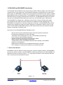
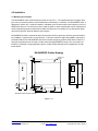
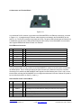
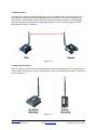
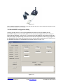
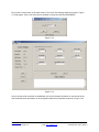
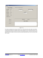
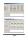
DN-2400E
DN-2400EP
2.4 GHz Wireless
Ethernet Bridges
User Guide
www.RFM.com
© 2011 by RF Monolithics, Inc.
Technical support +1.678.684.2000
E-mail: [email protected]
Page 1 of 21
DN-2400E User Guide - 08/05/11
Important Regulatory Information
RFM Product FCC ID: HSW-DN2400E
IC 4492A-DN2400E
Note: This unit has been tested and found to comply with the limits for a Class B digital device, pursuant
to Part 15 of the FCC Rules. These limits are designed to provide reasonable protection against harmful
interference when the equipment is operated in a commercial environment. This equipment generates,
uses, and can radiate radio frequency energy and, if not installed and used in accordance with the instruction manual, may cause harmful interference to radio communications. Operation of this equipment
in a residential area is likely to cause harmful interference in which case the user will be required to correct the interference at their expense.
FCC Antenna Gain Restriction:
The DN-2400E and DN-2400EP have been designed to operate with any dipole antenna of up to 9 dBi of
gain, or any patch of up to 6 dBi gain.
The antenna(s) used for this transmitter must be installed to provide a separation distance of at least
20 cm from all persons and must not be co-located or operating in conjunction with any other antenna or
transmitter.
IC RSS-210 Detachable Antenna Gain Restriction:
This device has been designed to operate with the antennas listed below, and having a maximum gain of
9 dBi. Antennas not included in this list or having a gain greater than 9 dBi are strictly prohibited for use
with this device. The required antenna impedance is 50 ohms:
RFM OMNI249 Omnidirectional Dipole Antenna, 9 dBi
RFM PA2400 Patch Antenna, 6 dBi
To reduce potential radio interference to other users, the antenna type and its gain should be so chosen
that the Equivalent Isotropically Radiated Power (EIRP) is not more than that permitted for successful
communication.
Changes or modifications to a DN-2400E or DN-2400EP not expressly approved by RFM may void the
user’s authority to operate the module.
www.RFM.com
© 2011 by RF Monolithics, Inc.
Technical support +1.678.684.2000
E-mail: [email protected]
Page 2 of 21
DN-2400E User Guide - 08/05/11
Table of Contents
1.0
DN-2400E and DN-2400EP Introduction ............................................................................................ 4
1.1
Point-to-Point Network ..................................................................................................................... 4
1.2
Point-to-Multipoint Network.............................................................................................................. 5
2.0
Operation ............................................................................................................................................ 5
3.0
Specifications ...................................................................................................................................... 6
3.1
Absolute Maximum Ratings ................................................................................................................ 6
3.2
System Specifications ......................................................................................................................... 6
3.3
LED Indicators..................................................................................................................................... 6
4.0
Installation ........................................................................................................................................... 7
4.1
Mounting and Location........................................................................................................................ 7
4.2
Connector and Terminal Block............................................................................................................ 8
5.0
Configuration Options ......................................................................................................................... 9
6.0
DN-2400ESK and DN-2400EPSK Starter Kits ................................................................................. 11
6.1
Items Supplied with Each DN-2400ESK/EPSK Starter Kit ............................................................ 11
6.2
Getting Started............................................................................................................................... 12
6.3
Attaching the Antenna ................................................................................................................... 12
6.4
Ethernet Port Connections............................................................................................................. 12
6.5
Applying Power to the Units........................................................................................................... 13
6.6
Preparing to Change Default Settings ........................................................................................... 13
7.0
DN-2400E/EP Configuration Utility ................................................................................................... 14
8.0
Ordering Information ......................................................................................................................... 20
9.0
Warranty............................................................................................................................................ 21
www.RFM.com
© 2011 by RF Monolithics, Inc.
Technical support +1.678.684.2000
E-mail: [email protected]
Page 3 of 21
DN-2400E User Guide - 08/05/11
1.0 DN-2400E and DN-2400EP Introduction
The DN-2400E and DN-2400EP provide robust wireless 10 BaseT Ethernet bridge connections between
a base and one or more remote units. The DN-2400E is designed to be powered from an external DC
power supply. The DN-2400EP is designed to be powered from an external DC power supply or an IEEE
802.3af Mode B Power-over-Ethernet host. The DN2400E/EP wireless link is implemented using RFM’s
DNT2400 Frequency Hopping Spread Spectrum transceivers. The DN-2400E/EP features RF transmission rates up to 500 kbps and transmitter power levels up to 100 mW EIRP using a 2 dBi antenna.
The DN-2400E/EP is supplied with a 2 dBi dipole antenna and a universal wall-plug power supply,
plus an Ethernet cable. Optional directional antennas are available to extend operating range. The
DN-2400E/EP are shipped from the factory configured as “Remotes”. All DN-2400E/EP factory default
settings can be changed as needed for a specific application, as described in Sections 5 and 7 of this
guide. The DN-2400E and DN-2400EP bridges are well suited for Ethernet sensor networks and data
networks carrying light to moderate traffic.
Key Features of the DN-2400E/EP Ethernet Bridges include:
- Nine 2.4 GHz Frequency Subbands Support License-free Operation World-wide
- RF Data Rate Configurable from 38.4 to 500 kbps
- Transmitter Power Configurable from 1.58 to 100 mW EIRP (2 dBi Antenna)
- Point-to-Point or Point-to-Multipoint Operation
- Optional 128-Bit AES Encryption and Authentication Modes
- Wide DC Power Supply Operating Voltage Range
- 10 BaseT Ethernet Port, with IEEE802.3af Mode B PoE capability on DN-2400EP
- Serial Port for Configuration
- Rugged Aluminum Enclosure can be Mounted Horizontally or Vertically
- FCC, Canadian IC Certified and CE Marked for Unlicensed Operation
1.1 Point-to-Point Network
DN-2400E/EP units can operate in either point-to-point or point-to-multipoint networks. A DN-2400E/EP
point-to-point network consists of one DN-2400E/EP configured as the Base and one DN-2400E/EP configured as a Remote, as shown in Figure 1.1.1. In a point-to-point network, it does not matter which device is connected to the main Ethernet network.
Figure 1.1.1
www.RFM.com
© 2011 by RF Monolithics, Inc.
Technical support +1.678.684.2000
E-mail: [email protected]
Page 4 of 21
DN-2400E User Guide - 08/05/11
1.2 Point-to-Multipoint Network
A DN-2400E/EP point-to-multipoint point network consists of one DN-2400E/EP configured as the Base
and up to 16 DN-2400E/EPs configured as Remotes. See Figure 1.2.1. In a point-to-multipoint network,
the base should be connected to the main Ethernet network segment since all remote transmissions are
sent to the base.
Figure 1.2.1
DN-2400E/EP networks function as a MAC layer bridges, with no IP address filtering. Any Ethernet
packet received by a DN-2400E/EP will be transmitted over the air. If the DN-2400E/EP is used on an
Ethernet network that includes information that should not be transmitted by a DN-2400E/EP, it should be
placed behind an Ethernet switch that can perform the required filtering.
2.0 Operation
Data signals to and from the DNT2400 radio within a DN-2400E/EP are routed through a signal switch. In
normal operation, the switch routes these signal to/from the Ethernet MAC/PHY microcontroller, providing
transparent 10 BaseT Ethernet packet transmission and reception.
Grounding the CONFIG pin changes the DNT2400 data signal routing to the data input (DI) and data output (DO) terminals, allowing radio configuration parameters to be adjusted to specific application requirements, as discussed in Section 5. The switching regulator used in the DN-2400E/EP supports a wide input voltage range, from 9 to 48 Vdc.
www.RFM.com
© 2011 by RF Monolithics, Inc.
Technical support +1.678.684.2000
E-mail: [email protected]
Page 5 of 21
DN-2400E User Guide - 08/05/11
3.0 Specifications
3.1 Absolute Maximum Ratings
Rating
Value
Power Supply Input Voltage Range
-0.5 to +48
Non-Operating Ambient Temperature Range
-40 to +85
Units
V
o
C
3.2 System Specifications
Characteristic
Sym Notes
Operating Frequency Range
Hop Dwell Time
Minimum
Typical
Maximum
Units
2409.3
2467.1
MHz
5
200
ms
Number of Frequency Hopping Subbands
9
Number of RF Channels in a Subband
15
37
Modulation
FSK/MSK
RF Data Transmission Rates
38.4, 115.2, 200 and 500
kbps
Receiver Sensitivity:
10-5 BER @ 38.4 kb/s
-104
dBm
10-5 BER @ 200 kb/s
-96
dBm
-90
dBm
10-5 BER @ 500 kb/s
EIRP RF Output Power Levels (2 dBi Antenna)
1.58, 15.8, 100
Optimum Antenna Impedance
mW
Ω
50
RF Connection
RSMA Coaxial Connector
Network Topologies
Point-to-Point, Point-to-Multipoint
Access Schemes
TDMA
Number of Remote Nodes
1
16
RJ-45 Ethernet Port
10 BaseT
Serial Configuration Port Baud Rate
115.2
Power Supply Voltage Range, DN-2400E/EP
VCC
Power over Ethernet Standard, DN-2400EP (only)
+48
V
5
W
IEEE 802.3af Mode 2
Power Consumption
Nominal Dimensions
kbps
+9
3.3 x 3.2 x 1 inches (84.6 x 82.0 x 25.4 mm)
Left and Right Flanges, Two Pre-drilled Holes
in Each Flange
Mounting
Operating Temperature Range
-40
85
o
Operating Relative Humidity Range, Non-condensing
10
90
%
C
3.3 LED Indicators
Ref
Name
I/O
1
ACTIVITY
O
Left-most LED on the front of the unit, amber, indicates RF communications activity.
2
LINK
O
Middle LED on the front of the unit, red. On a base, this LED indicates one or more remotes
are linked to it. On a remote, this LED indicates it is linked to the base.
3
POWER
O
Right-most LED on the front of the unit, green, indicates the unit is powered up.
4
ETH LINK
O
Upper-left LED on the RJ-45 Ethernet connector, green, indicates the Ethernet port is linked.
5
ETH ACT
O
Upper-right LED on the RJ-45 Ethernet connector, amber, indicates Ethernet port communications activity.
www.RFM.com
© 2011 by RF Monolithics, Inc.
Description
Technical support +1.678.684.2000
E-mail: [email protected]
Page 6 of 21
DN-2400E User Guide - 08/05/11
4.0 Installation
4.1 Mounting and Location
The DN-2400E/EP case outline drawing is shown in Figure 4.1.1. The supplied antenna is hinged, allowing it to be set vertically with the case mounted either horizontally or vertically. The DN-2400E/EP case is
designed for indoor use. It must be installed in a weather proof enclosure when used outdoors, such as a
NEMA 4X enclosure. The enclosure must be made of plastic or other materials with low RF attenuation to
avoid compromising antenna performance. Metal enclosures are not suitable for use with internal antennas as they will block antenna radiation and reception.
DN-2400E/EP should be mounted at least six feet above the floor (ground) to achieve good communication reliability in a typical office or retail location. To achieve maximum range and reliability, especially in
industrial locations, the DN-2400E/EP should be mounted as high as practical. RFM offers a number of
high gain antennas that can be used to further extend the DN-2400E/EP’s range. The use of these antennas is not allowed in all geographical regions; contact RFM’s technical service department for additional details.
D N -2 4 0 0 E /E P O u tlin e D r a w in g
0 .1 5 0
(3 .8 1 )
D C P o w e r
a n d R S 2 3 2
C o n n e c to r
R 0 .0 7 5 (1 .9 1 )
4 P la c e s
2 .4 1 2
(6 1 .2 6 )
E th e rn e t
C o n n e c to r
3 .3 3 2
(8 4 .6 3 )
0 .4 6 0
(1 1 .6 8 )
1 .0 0
(2 5 .4 )
0 .1 5 0
(3 .8 1 )
0 .7 9 5
(2 0 .1 9 )
2 .4 3 5
(6 1 .8 5 )
3 .2 3 0
(8 2 .0 )
D im e n s io n s s h o w n in in c h e s a n d (m m )
Figure 4.1.1
www.RFM.com
© 2011 by RF Monolithics, Inc.
Technical support +1.678.684.2000
E-mail: [email protected]
Page 7 of 21
DN-2400E User Guide - 08/05/11
4.2 Connector and Terminal Block
Figure 4.2.1
A conventional RJ-45 connector is provided on the DN-2400E/EP for the Ethernet connection, as shown
in Figure 4.2.1. A “straight through” Ethernet cable should be used between the DN-2400E/EP and its
host PC, etc. The RJ-45 connector incorporates two LEDs. The green LED indicates that an Ethernet link
is established, and the amber LED indicates Ethernet traffic activity. On the DN-2400EP, this connector
also supports IEEE 802.3af Mode B Power over Ethernet.
RJ-45 Ethernet Connector
Pin
Name
I/O
Description
1
TX+
O
Ethernet positive differential output.
2
TX-
O
Ethernet negative differential output.
3
RX+
I
Ethernet positive differential input.
4
DC+
I
Power over Ethernet DC+ input on the DN-2400EP. Not used on the DN-2400E.
5
DC+
I
Power over Ethernet DC+ input on the DN-2400EP. Not used on the DN-2400E.
6
RX-
I
Ethernet negative differential input.
7
DC-
I
Power over Ethernet DC- input on the DN-2400EP. Not used on the DN-2400E.
8
DC-
I
Power over Ethernet DC- input on the DN-2400EP. Not used on the DN-2400E.
A six-pin terminal block is also provided on the DN-2400E/EP for serial port and DC power connections,
as detailed below. The pin numbers read left-to-right as shown by the silkscreen above the connector.
Grounding Pin 3 switches the DNT2400E/EP radio signals from the Ethernet port to Pins 1 and 2 on the
terminal block, allowing the DN-2400E/EP to be configured as discussed in Section 5 below. DC power is
input to this terminal block on Pins 5 (+) and 6 (-).
Serial Port/DC Power Terminal Block
Pin
Name
I/O
Description
1
DI
I
This terminal receives serial configuration data transmitted from the host.
2
DO
O
This terminal transmits response data to the host.
3
CONFIG
I
Connecting this terminal to either ground terminal 4 or 5 routes DI and DO to the corresponding pins on the radio transceiver, allowing the transceiver to be configured.
4
SIG GND
-
DN-2400E signal ground.
5
+ (PWR)
I
Positive power supply input, 9 to 48 V.
6
- (PWR)
-
Power supply ground.
www.RFM.com
© 2011 by RF Monolithics, Inc.
Technical support +1.678.684.2000
E-mail: [email protected]
Page 8 of 21
DN-2400E User Guide - 08/05/11
5.0 Configuration Options
The following are the DN-2400E/EP parameters that can be configured by the user:
Parameter
Default Value
TX Power
0 dBm (1.58 mW EIRP)
RF Data Rate
Auto
Network ID
Base uses last two digits of MAC address
Remotes default to 0xFF which is any network ID
Encryption Security Key
All NULL bytes (disabled)
Hop Duration
10 ms
Device Mode
Remote
TDMA Max Slots
4
Frequency Subband
Entire band (subband 0)
Remote Authentication Mode
Any remote allowed
User Tag
DNT2400
TX Power - this parameter sets the transmit power level used by the base (fixed), and the maximum
transmit power level used by a remote. A remote may automatically adjust its power below the RF power
settings based on the signal strength it receives from the base plus the RF Power setting being used by
the base. The 1.58 mW EIRP RF setting is useful for desktop testing. RF Power is usually set to the highest level allowed by local radio regulations to increase operating range in an actual application. Setting bit
4 (0001xxxx) disables the remote automatic transmit power function.
0 = 1.58 mW (default)
1 = 15.8 mW
2 = 100 mW
RF Data Rate - this sets the over-the-air data rate. DN-2400E/EP’s with different RF data rates cannot
intercommunicate. The following codes are defined:
0
1
2
3
255
=
=
=
=
=
500 kb/s (default)
200 kb/s
115.2 kb/s
38.4 kb/s
Auto
Network ID - this parameter sets the network ID that a base will use to start a network, or a remote will be
allowed to join. A value of 0xFF instructs a remote to operate in “promiscuous mode” and join any network it finds (if set for a base, this will select the default network ID of 0x00.)
The auto setting will cause a remote to try all four over-the-air rates when scanning for a network to join.
Setting the RF_DataRate parameter to a fixed value on the remotes will allow a network to link much
faster than using the auto setting. However, if the base RF_DataRate is changed when the remotes are
set to a fixed rate, the network will not link. Note that changing this setting does not take effect immediately. It must be followed by a MemorySave command and then a hardware reset.
Encryption Security Key - the DN-2400E/EP supports 128-bit AES encryption of data and configuration
packets. Encryption is enabled by setting this key to a value other than a string of NULL (0x00) bytes. A
remote without encryption enabled cannot link to an encrypted base, and an encrypted remote will not
attempt to link to an unencrypted base. A remote's encryption key must match that of the base before it
www.RFM.com
© 2011 by RF Monolithics, Inc.
Technical support +1.678.684.2000
E-mail: [email protected]
Page 9 of 21
DN-2400E User Guide - 08/05/11
can link. The Encryption key can be set over the air so it can be changed periodically if desired. Once an
encryption key has been entered, it can be changed but it cannot be read back.
Hop Duration - this sets the duration of the hop frame. The duration is set as a 12-bit value,
0.05 ms/count. Changing the hop duration must be followed by a MemorySave command to allow the
change to persist through a reset or power cycle. A HopDuration change takes effect immediately. Remotes will re-link following a HopDuration parameter change.
Device Mode - selects the operating mode for the radio: remote, base or router. Note that changing this
setting does not take effect immediately. It must be followed by a Memory Save command and then a
hardware reset.
TDMA Max Slots - this sets the number of slots that are allowed. In fixed slot mode, this allocates the
number of slots directly. In dynamic slot mode, this sets the maximum number of slots that may be generated regardless of the number of remotes that attempt to link with the base. Any remotes requesting registration after this limit is reached will be denied registration by the base.
Frequency Subband - a suitable frequency subband depends on geographical location. For example, the
default subband can be used in locations such as the US or Canada. Operation in France requires the
use of subbands 4, 5 or 7 as the 2.4 GHz frequency band for unlicensed radios is smaller in France.
Subband
Channels
Frequency Range(s)
Notes
0
37
2409.3-2467.1 MHz
General purpose 37 channel subband
1
17
2441.1-2467.1 MHz
17 channel subband, avoids 802.11b/g channels 1-4
2
17
2409.3-2416.6 MHz, 2451.2-2467.1 MHz
17 channel subband, avoids 802.11b/g channels 5-6
3
17
2409.3-2426.7 MHz, 2461.3-2467.1 MHz
17 channel subband, avoids 802.11b/g channels 7-8
4
17
2409.3-2435.3 MHz
17 channel subband, avoids 802.11b/g channels
9-10, also for use in France
5
21
2409.3-2441.1 MHz
21 channel subband, avoids 802.11b/g channels
11-13, also for use in France
6
21
2428.1-2461.3 MHz
21 channel subband, avoids 802.11 b/g channel 1
7
15
2409.3-2432.4 MHz
15 channel subband, avoids 802.11b/g channels
8-13, also for use in France
8
15
2433.9-2455.6 MHz
15 channel subband, avoids 802.11b/g channels
1-2 and 13
255
15 to 37
Auto
Autoscan for remote to match base
Remote Authentication Mode - this parameter is set in the base. It controls how remotes are permitted to
join the network. Permitted values are:
0 = Any remote may join
1 = Authentication by base radio permission table
UserTag - this is a user definable field intended for use as a location description or other identifying tag
such as a “friendly name”.
www.RFM.com
© 2011 by RF Monolithics, Inc.
Technical support +1.678.684.2000
E-mail: [email protected]
Page 10 of 21
DN-2400E User Guide - 08/05/11
6.0 DN-2400ESK and DN-2400EPSK Starter Kits
It is highly recommended that a Starter Kit containing two DN-2400E or DN-2400EP units be purchased
initially for installing a network. The Starter Kit enables you to set up a point-to-point Ethernet connection
very quickly using the units default settings. The Kit also contains all the necessary hardware and software to make any changes to the default settings required by your application. Additional Remotes can
then be added to the point-to-point network to form a point-to-multipoint network.
Figure 6.0.1
6.1 Items Supplied with Each DN-2400ESK/EPSK Starter Kit
The Starter Kit contains the following:
•
•
•
•
•
•
•
Two Wireless Ethernet Bridges (one Base and one Remote)
Two Antennas
Two Universal Wall Plug Power Supplies
Two Ethernet Cables
One Configuration Module with Universal Wall Plug Power Supply
One DB9 M/F Cable
CD with Documentation and Configuration Software
www.RFM.com
© 2011 by RF Monolithics, Inc.
Technical support +1.678.684.2000
E-mail: [email protected]
Page 11 of 21
DN-2400E User Guide - 08/05/11
6.2 Getting Started
The Starter Kit contains two Ethernet Bridge units. One unit is labeled “Base” and the second unit is labeled “Remote”. These are the default configurations set at the factory. They can be changed as explained below. The DN-2400E units are powered using the included power supplies. The DN-2400EP
units can be powered either with the included power supplies or a from hosts that implements IEEE
802.3af Mode B Power over Ethernet.
Figure 6.2.1
6.3 Attaching the Antenna
Attach an antenna to each unit by screwing the antenna onto the antenna connector. The supplied antennas are hinged, allowing them to be set vertically with the case mounted either horizontally or vertically as
shown in Figure 6.3.1.
Figure 6.3.1
www.RFM.com
© 2011 by RF Monolithics, Inc.
Technical support +1.678.684.2000
E-mail: [email protected]
Page 12 of 21
DN-2400E User Guide - 08/05/11
6.4 Ethernet Port Connections
Using the Ethernet cables provided in the Kit, connect one end of the cable to the back of each
DN-2400E/EP and the other end to their respective Ethernet hosts. The green LED on the DN-2400E/EP
Ethernet connector indicates that an Ethernet link is established, and the amber LED indicates Ethernet
traffic activity.
Figure 6.4.1
6.5 Applying Power to the Units
Connect the power supply to the Base unit using the power supply connector on the rear of the unit. Connect the wall-mount end of the power supply to a wall outlet with either 110 or 220 VAC. The Power LED
on the unit will come on indicating that the unit is powered. Repeat this step with the Remote unit. Note
that it is not necessary to connect the power supply to a DN-2400EP if it is connected to an Ethernet host
that implements IEEE 802.3af Mode B Power over Ethernet. A few seconds after power is applied, the
Link LEDs on both units will light. This indicates the two units have established a wireless link and can
transport Ethernet traffic.
6.6 Preparing to Change Default Settings
This Section explains how to make hardware preparations to change DN-2400E/EP default settings such
as transmitter power, RF data rate, AES encryption key, hop duration etc., or to add more Remote units
to the network.
1. Snap the appropriate power plug on the universal wall plug power supply connected to the configuration module, as shown in Figure 6.6.1.
2. Connect the configuration module to a PC using a DB9 modem (straight through) cable.
3. Plug the configuration module into the DN-2400E/EP terminal block, and then plug in the wall plug
power supply.
4. Configure the module as needed (see Section 7 for details).
www.RFM.com
© 2011 by RF Monolithics, Inc.
Technical support +1.678.684.2000
E-mail: [email protected]
Page 13 of 21
DN-2400E User Guide - 08/05/11
Figure 6.6.1
Note: An additional configuration module with CD, power supply and serial cable can be order from RFM if the configuration module
that comes with the Starter Kit is lost or damaged.
7.0 DN-2400E/EP Configuration Utility
Create a file folder on the PC and copy the DNWizard.exe utility from the CD supplied with the
DN-2400E/EP Starter Kit into the folder. DNWizard.exe requires no installation and can be simply run.
Before starting DNWizard, confirm the PC is connected to the DN-2400E/EP configuration module with a
DB9 serial modem (straight through) cable, and ensure that the configuration module is fully plugged into
the DN-2400E/EP terminal block and powered from the wall plug power supply (green LED on the front of
the DN-2400E illuminated). The DNWizard main window is shown in Figure 7.0.1.
Figure 7.0.1
www.RFM.com
© 2011 by RF Monolithics, Inc.
Technical support +1.678.684.2000
E-mail: [email protected]
Page 14 of 21
DN-2400E User Guide - 08/05/11
Click on the Connect button in the main window. The Comm Port Settings dialog box shown in Figure
7.0.2 will appear. Click on the OK button to establish a connection with the DN-2400E/EP.
Figure 7.0.2
Figure 7.0.3
As soon as the serial connection is established, the Current Settings information on the left side of the
main window and the information on all configuration tabs will be populated, as shown in Figure 7.0.3.
www.RFM.com
© 2011 by RF Monolithics, Inc.
Technical support +1.678.684.2000
E-mail: [email protected]
Page 15 of 21
DN-2400E User Guide - 08/05/11
Figure 7.0.4
Note that all DN-2400E/EP wireless bridges ordered as single units outside of the Starter Kit are shipped
configured as Remote units.
One DN-2400E/EP in each network must be configured as a Base. All traffic to and from other bridges in
the DN-2400E/EP network will flow through the base. Figure 7.0.4 shows a DN-2400E/EP being reconfigured from a Remote to a Base.
A change to the Device Mode parameter and/or the RF Data Rate parameter will not take effect until the
Apply Changes Button is clicked and the DC power to the DN-2400E/EP is cycled off and back on. All
other parameter changes become effective when the Apply Changes button is clicked. Clicking the Refresh button updates any changes in Current Settings or on the configuration tabs.
As discussed in Section 5, the default Transceiver Setup values allow a remote to immediately join to a
nearby unencrypted base. TX Power should be set to 10 dBm in Europe or 18 dBm in North America for
most installations. The 0 dBm default value is suitable for pretesting a DN-2400E/EP network on a tabletop before installation.
www.RFM.com
© 2011 by RF Monolithics, Inc.
Technical support +1.678.684.2000
E-mail: [email protected]
Page 16 of 21
DN-2400E User Guide - 08/05/11
Figure 7.0.5
The System configuration tab is shown in Figure 7.0.5. In France and some other regions, only specific
Frequency Band settings are compatible with local radio regulations. This is discussed in Section 5. The
Auth Mode drop down control allows the selection of Any Remote (default), or By Base Table. Selecting
By Base Table on the Base unit allows only the remote MAC addresses input on the Auth List tab to join
with the Base.
www.RFM.com
© 2011 by RF Monolithics, Inc.
Technical support +1.678.684.2000
E-mail: [email protected]
Page 17 of 21
DN-2400E User Guide - 08/05/11
Figure 7.0.6
The read only Status tab shown in Figure 7.0.6 displays information about the DNT2400 radio embedded
in the DN-2400E/EP, plus related network information.
Figure 7.0.7
www.RFM.com
© 2011 by RF Monolithics, Inc.
Technical support +1.678.684.2000
E-mail: [email protected]
Page 18 of 21
DN-2400E User Guide - 08/05/11
When By Base Table is selected for Auth Mode on the System tab of a Base, only remotes with their
MAC addresses loaded on the Auth List tab shown in Figure 7.0.7 will be allowed to join with the Base.
Figure 7.0.8
Figure 7.0.9
The 0x0002E0 MAC address of the DN-2400E/EP in Figure 7.0.8 is shown loaded in the Approved Addr0
field above. The 0xFFFFFF in the rest of the approved address fields indicates no assignment.
www.RFM.com
© 2011 by RF Monolithics, Inc.
Technical support +1.678.684.2000
E-mail: [email protected]
Page 19 of 21
DN-2400E User Guide - 08/05/11
8.0 Ordering Information
The part numbers of the products that comprise the DN-2400 Series Ethernet Bridge product line are
listed below to facilitate ordering:
DN-2400E - 2.4 GHz Wireless Ethernet Bridge, including a 2 dBi Dipole Antenna, Universal Wall Plug
Power Supply and Ethernet Cable
DN-2400EP - 2.4 GHz Wireless Ethernet Bridge with Power-over-Ethernet option, including a 2 dBi Dipole
Antenna, Universal Wall Plug Power Supply and Ethernet Cable
DN-2400ESK - 2.4 GHz Wireless Ethernet Bridge Starter Kit, including two DN-2400E Ethernet Bridge
Units, 2 Dipole Antennas, 2 Universal Wall Plug Power Supplies, 2 Ethernet Cables, a Configuration Module with attached Power Supply, a DB9 cable and a CD containing configuration software and documentation.
DN-2400EPSK - 2.4 GHz Wireless Ethernet Bridge Starter Kit with IEEE 802.3af Mode B Power-overEthernet option, including two DN-2400EP Ethernet Bridge Units, 2 Dipole Antennas, 2 Universal Wall
Plug Power Supplies, 2 Ethernet Cables, a Configuration Module with attached Power Supply, a DB9 cable and a CD containing configuration software and documentation.
DN-2400E-OEM - 10-Pack of DN-2400E 2.4 GHz Wireless Ethernet Bridges. Includes a 10-pack of pluggable 6 position connectors for attaching an OEM power supply (no antennas, cables or power supplies
are included). Includes a 10-pack of pluggable 6 position connectors for attaching an OEM power supply
(no antennas, cables or power supplies are included).
DN-2400EP-OEM - 10-Pack of DN-2400EP 2.4 GHz Wireless Ethernet Bridges with IEEE 802.3af Mode
B Power-over-Ethernet option. Includes a 10-pack of pluggable 6 position connectors for attaching an
OEM power supply (no antennas, cables or power supplies are included).
DN-EB-CFG - Configuration Module for DN-2400E/EP Wireless Ethernet bridges, including a Universal
Wall Plug Power Supply, a DB9 Cable and a CD containing configuration software and documentation
www.RFM.com
© 2011 by RF Monolithics, Inc.
Technical support +1.678.684.2000
E-mail: [email protected]
Page 20 of 21
DN-2400E User Guide - 08/05/11
9.0 Warranty
Seller warrants solely to Buyer that the goods delivered hereunder shall be free from defects in materials
and workmanship, when given normal, proper and intended usage, for twelve (12) months from the date
of delivery to Buyer. Seller agrees to repair or replace at its option and without cost to Buyer all defective
goods sold hereunder, provided that Buyer has given Seller written notice of such warranty claim within
such warranty period. All goods returned to Seller for repair or replacement must be sent freight prepaid
to Seller’s plant, provided that Buyer first obtain from Seller a Return Goods Authorization before any
such return. Seller shall have no obligation to make repairs or replacements which are required by normal
wear and tear, or which result, in whole or in part, from catastrophe, fault or negligence of Buyer, or from
improper or unauthorized use of the goods, or use of the goods in a manner for which they are not designed, or by causes external to the goods such as, but not limited to, power failure. No suit or action
shall be brought against Seller more than twelve (12) months after the related cause of action has occurred. Buyer has not relied and shall not rely on any oral representation regarding the goods sold hereunder, and any oral representation shall not bind Seller and shall not be a part of any warranty.
THE PROVISIONS OF THE FOREGOING WARRANTY ARE IN LIEU OF ANY OTHER WARRANTY,
WHETHER EXPRESS OR IMPLIED, WRITTEN OR ORAL (INCLUDING ANY WARRANTY OR
MERCHANT ABILITY OR FITNESS FOR A PARTICULAR PURPOSE). SELLER’S LIABILITY ARISING
OUT OF THE MANUFACTURE, SALE OR SUPPLYING OF THE GOODS OR THEIR USE OR
DISPOSITION, WHETHER BASED UPON WARRANTY, CONTRACT, TORT OR OTHERWISE, SHALL
NOT EXCEED THE ACTUAL PURCHASE PRICE PAID BY BUYER FOR THE GOODS. IN NO EVENT
SHALL SELLER BE LIABLE TO BUYER OR ANY OTHER PERSON OR ENTITY FOR SPECIAL,
INCIDENTAL OR CONSEQUENTIAL DAMAGES, INCLUDING, BUT NOT LIMITED TO, LOSS OF
PROFITS, LOSS OF DATA OR LOSS OF USE DAMAGES ARISING OUT OF THE MANUFACTURE,
SALE OR SUPPLYING OF THE GOODS. THE FOREGOING WARRANTY EXTENDS TO BUYER
ONLY AND SHALL NOT BE APPLICABLE TO ANY OTHER PERSON OR ENTITY INCLUDING,
WITHOUT LIMITATION, CUSTOMERS OF BUYERS.
Part # M-2400-3004, Rev A
www.RFM.com
© 2011 by RF Monolithics, Inc.
Technical support +1.678.684.2000
E-mail: [email protected]
Page 21 of 21
DN-2400E User Guide - 08/05/11