1
Aruba RF Plan
For Windows
v2.0.3 User’s Guide
180 Great Oaks Blvd. Ste B
San Jose, California 95119
Net www.arubanetworks.com
Tel 408.227.4500
Fax 408.227.4550
TM
Copyright
Copyright © 2004 Aruba Wireless Networks, Inc. All rights reserved.
Specifications in this manual are subject to change without notice.
Originated in the USA.
Trademarks
RF Director, AirOS, Aruba 5000, and Aruba 52 are trademarks of Aruba Wireless Networks, Inc. in the
United States and certain other countries.
Any other trademarks appearing in this manual are the property of their respective companies.
Legal Notice
The use of Aruba Wireless Networks Inc. switching platforms and software, by all individuals or corporations,
to terminate Cisco VPN client devices constitutes complete acceptance of liability by that individual or corporation for this action and indemnifies, in full, Aruba Wireless Networks Inc. from any and all legal actions that
might be taken against it with respect to infringement of copyright on behalf of Cisco Corporation.
ii
Aruba RF Plan
v2.0.3 User’s Guide
Part 0500030-01
January 2004
Table of Contents
Preface . . . . . . . . . . . . . . . . . . . . . . . v
Related Documents . . . . . . . . . . . . . . . . . . . v
Text Conventions . . . . . . . . . . . . . . . . . . . vi
Contacting Aruba Wireless Networks . . . . . . . . .
vii
The Aruba RF Plan Tool . . . . . . . . . . 1
Getting Started . . . . . .
System Requirements
Installing RF Plan . .
Launching RF Plan . .
.
.
.
.
.
.
.
.
.
.
.
.
.
.
.
.
.
.
.
.
.
.
.
.
.
.
.
.
.
.
.
.
.
.
.
.
.
.
.
.
.
.
.
.
.
.
.
.
.
.
.
.
.
.
.
.
.
.
.
.
2
2
2
2
RF Plan Basics . . . . .
Page Summary . . .
Screen Layout . . .
Page Fields . . . . .
Applying and Saving
Next Step Button. .
.
.
.
.
.
.
.
.
.
.
.
.
.
.
.
.
.
.
.
.
.
.
.
.
.
.
.
.
.
.
.
.
.
.
.
.
.
.
.
.
.
.
.
.
.
.
.
.
.
.
.
.
.
.
.
.
.
.
.
.
.
.
.
.
.
.
.
.
.
.
.
.
.
.
.
.
.
.
.
.
.
.
.
.
.
.
.
.
.
.
3
3
4
4
5
5
.
.
.
.
.
.
Table of Contents
iii
iv
Aruba RF Plan
v2.0.3 User’s Guide
Using RF Plan . . . . . . . . . . . . . . . .
Task Overview . . . . . . . . . . . . . .
Planning Requirements . . . . . . . . . .
Building Pages . . . . . . . . . . . . . .
Building List Page . . . . . . . . . .
Building Specifications Overview Page
Building Specification Page . . . . .
AP Modeling Page . . . . . . . . . .
AM Modeling Page . . . . . . . . .
Import and Export . . . . . . . . . .
Planning Pages . . . . . . . . . . . . . .
Planning Floors Page . . . . . . . .
Floor Editor Page . . . . . . . . . .
Area Editor Page . . . . . . . . . . .
Access Editor Page . . . . . . . . . .
AP Plan . . . . . . . . . . . . . . .
AM Plan . . . . . . . . . . . . . .
.
.
.
.
.
.
.
.
.
.
.
.
.
.
.
.
.
.
.
.
.
.
.
.
.
.
.
.
.
.
.
.
.
.
.
.
.
.
.
.
.
.
.
.
.
.
.
.
.
.
.
.
.
.
.
.
.
.
.
.
.
.
.
.
.
.
.
.
.
.
.
.
.
.
.
.
.
.
.
.
.
.
.
.
.
6
6
7
8
. 8
. 9
10
12
14
16
18
18
20
21
22
24
27
RF Plan Tutorial . . . . . .
Our Sample Building . .
Create A Building . . .
Model the Access Points
Model the Air Monitors
Add and Edit a Floor . .
Defining Areas . . . . .
Running the AP Plan . .
Running the AM Plan .
.
.
.
.
.
.
.
.
.
.
.
.
.
.
.
.
.
.
.
.
.
.
.
.
.
.
.
.
.
.
.
.
.
.
.
.
.
.
.
.
.
.
.
.
.
28
28
29
30
30
31
33
36
36
.
.
.
.
.
.
.
.
.
.
.
.
.
.
.
.
.
.
.
.
.
.
.
.
.
.
.
.
.
.
.
.
.
.
.
.
.
.
.
.
.
.
.
.
.
.
.
.
.
.
.
.
.
.
.
.
.
.
.
.
.
.
.
.
.
.
.
.
.
.
.
.
.
.
.
.
.
.
.
.
.
Part 0500030-01
January 2004
Preface
This preface includes the following information:
z A list of related documentation for further reading
z A key to the various text conventions used throughout this manual
z Aruba Wireless Networks support and service information
Related Documents
The following items are part of the complete documentation for the Aruba system:
z Aruba AirOS User’s Guide
z Aruba RF Director Starter’s Guide
Preface
v
Text Conventions
The following conventions are used throughout this manual to emphasize important concepts:
TABLE 1 Text Conventions
Type Style
Description
Italics
This style is used to emphasize important terms and to mark the
titles of books.
System items
This fixed-width font depicts the following:
z Sample screen output
z System prompts
z Filenames, software devices, and certain commands when mentioned in the text.
Commands
In the command examples, this bold font depicts text that the user
must type exactly as shown.
<Arguments>
In the command examples, italicized text within angle brackets represents items that the user should replace with information appropriate to their specific situation. For example:
# send <text message>
In this example, the user would type “send” at the system prompt
exactly as shown, followed by the text of the message they wish to
send. Do not type the angle brackets.
vi
[ Optional ]
In the command examples, items enclosed in brackets are optional.
Do not type the brackets.
{ Item A | Item B }
In the command examples, items within curled braces and separated
by a vertical bar represent the available choices. Enter only one
choice. Do not type the braces or bars.
Aruba RF Plan
v2.0.3 User’s Guide
Part 0500030-01
January 2004
Contacting Aruba Wireless Networks
Web Site
z Main Site
http://www.arubanetworks.com
z Support
http://www.arubanetworks.com/support
E-mail
z Sales
[email protected]
z Support
[email protected]
Telephone Numbers
z Main
408-227-4500
z Fax
408-227-4550
z Sales
408-754-1201
z Support
In the U.S.: 800-WI-FI-LAN (800-943-4526)
International: 408-754-1200
Preface
vii
viii
Aruba RF Plan
v2.0.3 User’s Guide
Part 0500030-01
January 2004
The Aruba RF Plan Tool
RF Plan is a three-dimensional wireless deployment modeling tool that enables Network
Administrators to design an efficient Wireless Local Area Network (WLAN) for their corporate environment, optimizing coverage and performance, and eliminating complicated
WLAN network setup.
RF Plan provides the following critical functionality:
z Defines WLAN Coverage
z Defines WLAN environment security coverage
z Assesses equipment requirements
z Optimizes radio resources
z Creates an exportable WLAN profile that may be imported into an Aruba switch and be
used to configure and deploy the WLAN.
RF Plan provides a view of each floor, allowing Network Administrators to specify how Wi-Fi
coverage should be provided. RF Plan then provides coverage maps and AP/AM placement
locations.
Unlike other static site survey tools that require administrators to have intricate knowledge of
building materials and other potential Radio Frequency (RF) hazards, RF Plan calibrates coverage on the fly through a sophisticated RF calibration algorithm. This real-time calibration
lets administrators characterize the indoor propagation of RF signals in order to determine the
best channel and transmission power settings for each AP. Real-time calibration can be automatically programmed or manually undertaken at any time in order to quickly adapt to
changes in the wireless environment.
The Aruba RF Plan Tool
1
Getting Started
System Requirements
Aruba RF Plan requires the a PC with the following:
z Intel Pentium® III 800Mhz (minimum) or equivalent
z 128MB RAM
z 10MB available hard drive space
z Windows 2000 or Windows XP
z Microsoft Internet Explorer 6.0 (or higher)
z Macromedia Flash 6.0 (of higher) plug-in for Internet Explorer
Installing RF Plan
To install RF Plan, use the following procedure.
N OTE—RF Plan only runs on Windows 2000 and Windows XP.
1
Locate the file named Aruba RF Plan.zip.
2
Unzip the file.
3
Launch setup.exe.
The installer will automatically place the files in the following directory:
C:\Program Files\Aruba RF Plan
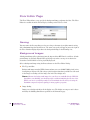
Launching RF Plan
Launching RF Plan is like any other Windows program installed on your PC. From the desktop taskbar, select the following:
Start > All Programs > Aruba Offline RF Plan > Aruba RF Plan
2
Aruba RF Plan
v2.0.3 User’s Guide
Part 0500030-01
January 2004
RF Plan Basics
Page Summary
The following is a summary of the functionality of each of the pages in RF Plan.
z Building List Page
The Building List is the first page displayed when RF Plan
is launched. This page provides a list of buildings that you
have created and saved. You may use this page to add or
delete buildings from you saved database. You may also
import or export buildings here.
z Building Specifications
Overview Page
The Building Specifications Overview page allows you to
see all the dimensional data and modeling parameters for
your buildings.
z Building Specification Page Specify the dimensions of your building and name it in the
Building Specifications page.
z AP Modeling Page
Specify the AP Modeling parameters on this page.
z AM Modeling Page
Specify the AM Modeling parameters on this page.
z Import and Export
Use this page to import and export building database files.
z Planning Floors Page
The Planning Floors page allows you to see approximate
coverages of APs and AMs, as well as any floor plans you
may have imported as background images.
z Floor Editor Page
Use this page to upload background images for each floor,
name the floor and delete floors.
z Area Editor Page
Use this page to specify areas on each floor where coverage
is not desirable or where Access Points/Air Monitors may
not be physically deployed.
z Access Editor Page
Use this page to manually create, position, or configure
Access Points or Air Monitors.
z AP Plan
The AP Plan page is used to initialize the position of
Access Points and launch RF Plan’s positioning algorithm.
z AM Plan
The AP Plan page is used to initialize the position of Air
Monitors and launch RF Plan’s positioning algorithm.
The Aruba RF Plan Tool
3
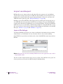
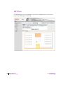
Screen Layout
When RF Plan is started, the browser window will show the default RF Plan page. For ease of
navigation, all of the pages in the RF Plan tool have a similar page structure. For example, as
shown on the Building Overview page:
Feature
Tree
Page
Display
Selected
Feature
FIGURE 1 RF Director Page Elements
z Feature Tree–Each feature has its own information or configuration pages and sub-pages.
The feature tree lists all of the available features. You can navigate to any of the listed features by clicking on the feature name.
z Selected Feature–The name of the currently selected feature is highlighted in the feature
tree.
z Page Display–This area displays all the information and/or input fields relevant to the
selected feature.
Page Fields
Each tool in the RF Plan has its own unique information or configuration pages, each with
specialized data and control fields. Some of the page items appear on multiple pages and provide a similar navigation or configuration function in each.
z Information Fields–These fields are used only for displaying information. The data in
these fields cannot be edited directly on the displayed screen.
z Data Entry Fields–Boxed text fields contain user-configurable data. To enter or edit the
information, click inside the field box.
4
Aruba RF Plan
v2.0.3 User’s Guide
Part 0500030-01
January 2004
z Pull-down Menus–These fields allow you to select an item from a preset list. The currently selected item is displayed in the box. When the arrow button is selected, a list of
available options will appear. You can change the current selection by clicking on any item
in the options list.
z Scrolling Menus–These fields allow you to select an item from a preset list. Use the scroll
arrows to view the available options. To select a specific item from the list, click on the
item when displayed.
z Check Boxes–These fields are represented as small squares in front of the item text. These
fields allow you to turn items on or off by clicking on the check box. A feature or option
will be turned on, selected, or enabled (as appropriate) when the box is checked. A feature
or option will be turned off, unselected, or disabled when the box is empty.
z Radio Buttons–These fields are represented as small circles in front of the item text.
When a group of these items appears together, only one can be selected at any given time.
An item is selected when its circle is filled. An item is unselected when the circle is empty.
Applying and Saving
When you edit information on any of the RF Plan pages you need to apply that information
before it is effective. However, applying the information doesn’t save it to your hard drive. You
must click on the Save button to permanently save the information.
The following buttons are generally available on configuration pages.
z Apply–Accept all configuration changes made on the current page (does not save
changes).
z Save–Save all applied configuration changes made since during this configuration session
to a database file. Unsaved configuration changes will be lost when the RF Plan tool is
exited.
NOTE–Always Apply. If you advance to the next step without clicking on the Apply button
the information will be lost.
Next Step Button
RF Plan will sequence you through all the pages as you setup your WLAN. When you have
finished entering the information for each page, click on the Next Step button located in the
upper right-hand portion of the page.
The Aruba RF Plan Tool
5
Using RF Plan
Task Overview
Before you begin, review the following points. These points outline the general steps to create
a building model and to plan the WLAN for it.
z Gather information about your building’s dimensions and floor plan
z Determine the level of coverage you want for your Access Points and Air Monitors
z Create a new building and add its dimensions
z Enter the parameters of your Access Point coverage
z Enter the parameters of your Air Monitor coverage
z Add floors to your building and import the floor plans
z Define special areas
z Generate suggested AP and AM tables by executing the AP/AM Plan features
z Export the building
6
Aruba RF Plan
v2.0.3 User’s Guide
Part 0500030-01
January 2004
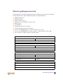
Planning Requirements
You should collect the following information before beginning to plan your network. Having
the information below readily available will expedite your planning efforts.
z
z
z
z
z
z
z
z
z
z
z
Building Dimensions
Number of floors
Distance between floors
Number of users and number of users per AP
Radio type(s)
Overlap Factor
Desired data rates for access points
Desired monitoring rates for air monitors
Areas of your building(s) that you don’t necessarily want coverage
Areas of your building(s) where you don’t want to, or cannot, deploy an AP or AM
Any area where you want to deploy a fixed AP or AM
Building Dimensions
Height:
Width:
Number of Floors:
User Information
Number of Users:
Users per AP:
Radio Types:
Overlap Factor:
AP Desired Rates
802.11b|g:
802.11a:
AM Desired Rates
802.11b|g:
802.11a:
Don’t Care/Don’t Deploy Areas
The Aruba RF Plan Tool
7
Building Pages
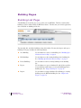
Building List Page
The Building list is the first page you see when you start RF Plan. This list contains all the
buildings you have defined using the RF Plan software. The first time you run the application,
there should be no buildings in the list.
You may add, edit, and delete buildings using this window. You may also import and export
buildings. This page includes the following buttons:
8
z New Building
Use this button to create a new building. See “Building Specifications Overview Page” on page 9.
z Edit Buildings
Use this button to edit existing buildings in the building list.
See “Building Specifications Overview Page” on page 9.
z Delete Buildings
Use this button to delete existing buildings in the building
list.
z Export
Use this button to export a database file with all the specifications and background images of a selected building(s) in the
building list. See “Import and Export” on page 16.
z Import
Use this button to import database files defining pre-existing
buildings into the RF Plan building list. See “Import and
Export” on page 16.
Aruba RF Plan
v2.0.3 User’s Guide
Part 0500030-01
January 2004
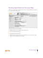
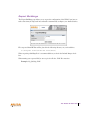
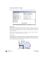
Building Specifications Overview Page
The Overview page shows the default values for your new or existing building, most of which
you can change in the following pages.
The Overview page includes the following:
z Building Dimensions: Your building’s name and dimensions
z Access Point Modeling Parameters
z Air Monitor Modeling Parameters
z Building Dimensions button (in the upper right-hand corner of the page). Click on this
button to edit the building dimensions settings.
The Aruba RF Plan Tool
9
Building Specification Page
The Building Specification Page is allows you to specify the identity of your building and its
dimensions. To access this page, click on the Building Dimension button in the upper righthand corner of the Building Specifications Overview page.
Naming Your Building
Naming your building is as simple as entering the correct values in the text boxes in the
Dimension window.
z Building ID
This consists of two decimal numbers separated by a dot. The first
is the campus ID. The campus ID will always be “1” if there is only
one campus. The second is the building number.
The valid range for these fields is any integer from 1 to 255.
z Building Name
Enter a user friendly name for the building.
The Building Name may be an alpha-numeric string up to 64 characters in length.
10
Aruba RF Plan
v2.0.3 User’s Guide
Part 0500030-01
January 2004
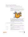
Dimensioning Your Building
Entering the correct values in the text boxes in the Dimension window.
z Width & Height
Enter the rectangular exterior dimensions of the building.
The valid range for this field is any integer from 1 to a value corre12
sponding to 1 ×10 .
If your building has an irregular shape, the width and height should
represent the maximum height and width of the overall footprint of
the building as seen from above,. For example:
Maximum Height
Maximum Width
When height and width are specified, RF Plan creates a rectangular
area in the Planning feature pages that represent the overall area
covered by the building. You will need to import an appropriate
background image (see “Floor Editor Page” on page 20.) to aid you
in defining areas that don’t require coverage or areas in which you do
not wish to deploy Access Points and Air Monitors (see “Area Editor
Page” on page 21).
z Inter-floor Height This is the distance between floor surfaces in the building.
The valid range for this field is any integer from 1 to a value corre12
sponding to 1 ×10 .
NOTE—This is not the distance from floor to ceiling. Some buildings
have a large space between the interior ceilings and the floor above.
z Floors
Enter the number of floors in your building here.
The valid range for this field is any integer from 1 to a value corresponding to 1 ×10¹² .
z Units
Specify the units of measurement for the dimensions you specified
on the page. The choices are feet and meters.
The Aruba RF Plan Tool
11
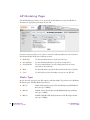
AP Modeling Page
The AP Modeling page allows you to specify all the information necessary for RF Plan to
determine the appropriate placement of your APs.
Controls on this page allow you to select or control the following functions, each of which is
described in further detail in the following sections:
z Radio Type
Use this pull-down menu to specify the radio type.
z Overlap Factor
Use this field and pull-down to specify an overlap factor.
z Design Model
Use these radio buttons to specify a design model to use in the
placement of Access Points.
z Rates
Use this pull-down to specify the data rates desired on Access Points.
z Users
Use this field to specify the number of users on your WLAN.
Radio Type
Specify the radio type(s) of your APs using the pull-down Radio Type menu on the Modeling
Parameters page. Available Radio Type Choices:
12
z 801.11a
5GHz, Orthogonal Frequency Division Multiplexing (OFDM) with
data rates up to 54Mbps.
z 802.11b
2.4GHz, Direct Spread Spectrum (DSSS) multiplexing with data
rates up to 11Mbps.
z 802.11g
2.4GHZ, OFDM/CCK (Complementary Code Keying) with data
rates up to 54Mbps.
Aruba RF Plan
v2.0.3 User’s Guide
Part 0500030-01
January 2004
Overlap Factor
The Overlap Factor is the amount of signal area overlap that you want when the APs are operating. Overlap is important if an AP fails. It allows the network to self-heal with adjacent APs
powering up to assume some of the load from the failed device. Although there may be no
holes in coverage in this scenario, there will likely be a loss of throughput. Increasing the overlap will allow for higher throughputs when an AP has failed and will allow for future capacity
as the number of users increases.
The valid range of values for the overlap factor are from 100% to 1000%.
Design Models
Three radio buttons on the page allow you to control the kind of model which will be used to
determine the number and type of APs.
Design Model Radio Button Options:
z Coverage
Use this option to let RF Plan automatically determine the number of
APs based on desired data rates and the configuration of your building.
z Capacity
Use this option to let RF Plan determine the number of APs based on
the total number of users, ratio of users to APs, and desired data rates.
z Custom
Use this option to simply specify a fixed number of APs.
The desired rate is selectable from 1 to 54 Mbps in both the Coverage and Capacity models.
Users
NOTE—The Users text boxes are active only when the Capacity model is selected.
Enter the number of users you expect to have on your WLAN in the Users text box. Enter the
number of users per access point you expect in the Users/AP text box.
The numbers entered in the these two text boxes must be no-zero integers between 1-255
inclusive.
Rates
NOTE—The Rate pull-down menus are active only when the Coverage or Capacity design
models are selected.
Select the desired data rates from the pull-down menus for 802.11b/g and 802.11a.
High data transmission rates will require an increased number of AP to be placed in your
building. You should carefully evaluate your user’s data rate needs.
The Aruba RF Plan Tool
13
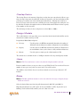
AM Modeling Page
The AM Modeling page allows you to specify all the information necessary for RF Plan to
determine the appropriate placement of your AMs.
Controls on this page allow you to select or control the following functions, which are
explained in more detail in the sections that follow:
14
z Design Model
Use these radio buttons to specify a design model to use in the
placement of Air Monitors.
z Monitor Rate
Use this pull-down menu to specify the desired monitor rate for
your Air Monitors.
z AMs
Use this field to manually specify the number of Air Monitors to
deploy (Custom Model only).
Aruba RF Plan
v2.0.3 User’s Guide
Part 0500030-01
January 2004
Design Models
Two radio buttons on the page allow you to control the kind of model which will be used to
determine the number and type of APs.
Design Model Radio Button Options:
z Coverage
Use this option to let RF Plan automatically determine the number
of AMs based on desired monitor rates and the configuration of
your building.
Desired rate is selectable from 1 to 54 Mbps in the Coverage model.
z Custom
Use this option to simply specify a fixed number of AMs. When the
AM Plan portion of RF Plan is executed, RF Plan will make an even
distribution of the AMs.
NOTE—The monitor rates you select for the AMs should be less than the data rates you
selected for the APs. If you set the rate for the AMs at a value equal to that specified for the
corresponding PHY type AP, RF Plan will allocate one AM per AP. If you specify a monitor
rate larger than the data rate, RF Plan will allocate more than one AM per AP.
Monitor Rates
Use the drop down menus to select the desired monitor rates for 802.11b/g and 802.11a air
monitors.
NOTE—This option is available only when the coverage design model is selected.
The Aruba RF Plan Tool
15
Import and Export
RF Plan allows you to import and export files that define the parameters of your buildings.
The files that you import and export are XML files and depending on how many floors your
buildings have, and particularly how many background images you have for your floors, the
XML files may be quite large. (See “Background Images” on page 20.)
Buildings exported from RF Plan will be imported into an Aruba switch and used by the version of RF Plan that is integrated into the RF Director Software. The exported building file
contains all the data about the building(s) you created using RF Plan. The integrated RF Plan
in RF Director gives you the ability to automatically configure the APs and AMs that are actually connected to the switch using the Suggested AP and Suggested AM tables created by RF
Plan. (See “AP Plan” on page 24 and “AM Plan” on page 27.)
Import Buildings
The Import Buildings page allows you to import configuration information from an existing
Aruba switch so you can modify it for use on another switch or in an another building.
Only XML files exported from an Aruba switch or from Aruba RF Plan may be imported into
RF Plan.
N OTE—Importing any other file, including XML files from other applications, may result in
unpredictable results.
Any file you wish to import must be in the C:\Program Files\Aruba RF Plan\data\ path. You
can not specify any other path in the RF Plan Import Buildings dialog.
16
Aruba RF Plan
v2.0.3 User’s Guide
Part 0500030-01
January 2004
Export Buildings
The Export Buildings page allows you to export the configuration of the WLAN you just created so that it may be imported into and used to automatically configure your Aruba switches.
Files exported from RF Plan will be placed in the following directory on your hard drive:
C:\Program Files\Aruba RF Plan\data\
When exporting a building file it is recommended that you check the Include Images check
box.
When naming your exported file, be sure to give the file the .XML file extension.
Example: My_Building.XML
The Aruba RF Plan Tool
17
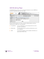
Planning Pages
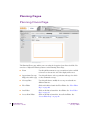
Planning Floors Page
The Planning Floors page enables you to see what the footprint of your floors look like. You
can select or adjust the following features on the Planning Floors Page.
18
z Zoom
Use this pull-down menu or type a zoom factor in the text field
to increase or decrease the size of the displayed floor area.
z Approximate Coverage
Map (select radio type)
Use this pull-down to select a particular radio type for which
to show estimated coverage.
z Coverage Rate
Use this pull-down to modify the coverage areas based on a
different data rate.
z Floor Editor
Click on this link to launch the Floor Editor. See “Floor Editor
Page” on page 20.
z Area Editor
Click on this link to launch the Area Editor. See “Area Editor
Page” on page 21.
z Access Point Editor
Click on this link to launch the Access Point Editor. See
“Access Editor Page” on page 22.
Aruba RF Plan
v2.0.3 User’s Guide
Part 0500030-01
January 2004
Zoom
The Zoom control sets the viewing size of the floor image. It is adjustable in finite views from
10% to 1000%. You may select a value from the pull-down zoom menu or specify a value in the
text box to the left of the pull-down. When you specify a value, RF Plan adjusts the values in the
pull-down to display a set of values both above and below the value you typed in the text box.
Coverage
Select a radio type from the Coverage pull-down menu to view the approximate coverage area
for each of the APs that RF Plan has deployed in AP Plan or AM Plan. Adjusting the Coverage
values will help you understand how the AP coverage works in your building.
NOTE—You will not see coverage circles displayed here until you have executed either an AP
Plan or an AM Plan.
Coverage Rate
Adjusting the coverage rate will also affect the size of the coverage circles for AMs. Adjusting
the rate values will help you understand how the coverage works in your proposed building.
The Aruba RF Plan Tool
19
Floor Editor Page
The Floor Editor allows you to specify the background image, and name the floor. The Floor
Editor is accessible from the Floors Page by clicking on the Edit Floor link.
Naming
You may name the floor anything you choose as long as the name is an alpha-numeric string
with a maximum length of 64 characters. The name you specify will appear just to the right of
the Floor Number displayed just above the background image in the Planning view.
Background Images
A background image (floor plan image) may be imported into RF Plan for each floor. A background image is extremely helpful when specifying areas where coverage is not desired or
areas where an AP/AM is not to be physically deployed.
Select a background image using the Browse button on the Floor Editor Dialog.
z File Type and Size
Background images must be JPEG format and may not exceed 2048 X 2048 pixels in size.
Attempting to import a file with a larger pixel footprint than that specified here will result
in the image not scaling to fit the image area in the floor display area.
N OTE—Because the background images for your floors are embedded in the XML file
that defines your building you should strongly consider minimizing the file size of the
JPEGs you use for your backgrounds. You can minimize the file size by selecting the
maximum compression (lowest quality) in most graphics programs.
z Image Scaling
Images are scaled (stretched) to fit the display area. The display area aspect ratio is determined by the building dimensions specified on the Dimension page.
20
Aruba RF Plan
v2.0.3 User’s Guide
Part 0500030-01
January 2004
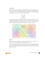
Area Editor Page
The area editor allows you to specify areas on your buildings floors where you either do not
care about coverage, or where you do not want to place an AP or AM.
Open the Area Editor by clicking on the New link in the Areas field just below the area where
the background image is displayed.
Area Editor “New” Link
You specify these areas by placing them on top of the background image using the Area Editor.
Naming
You may name an area using an alpha-numeric string of characters with a maximum length of
64 characters. You should give areas some meaningful name so that they are easily identified.
Locating and Sizing
You may specify absolute coordinates for the lower left corner and upper right corner of the box
that represents the area you are defining. The datum for measurement is the lower left corner
of the rectangular display area that represents your building’s footprint. The coordinates of the
upper right-hand corner of the display area are the absolute (no unit of measure) values of the
dimensions you gave your building when you defined it with the dimension feature.
NOTE—The location is zero-based. Values range from 0 to (height - 1 and width - 1).For
example: If you defined your building to be 200 feet wide and 400 feet long, the coordinates
of the upper right-hand corner would be (199, 399).
You may also use the drag and drop feature of the Area Editor to drag your area to where you
want it and resize it by dragging one or more of the handles displayed in the corners of the area.
Don’t Care areas are displayed as orange rectangles and Don’t Deploy areas are displayed as yellow
(Don’t Care)
(Don’t Deploy)
The Aruba RF Plan Tool
21
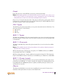
Access Editor Page
The Access Editor allows you to manually create or modify a suggested access point.
Naming
RF Plan automatically names APs using the default convention “ap number”. It assigns the
number starting at 1 and increasing by one for each new AP. When you manually create an AP
that new AP is then assigned the next “ap” number in sequence and added to the bottom of
the suggested AP list.
You may name an Access Point anything you wish. The name must be comprised of alphanumeric characters and be 64 characters or less in length.
Location
262 ft.
The physical location of the AP is specified by X-Y coordinates beginning at the lower left corner of the display area. The numbers you specify in the X and Y text boxes are whole units.
The X coordinates increase as a point moves up the display and the Y coordinates increase as
they move from left to right across the display.
Y
98
0,0
22
Aruba RF Plan
v2.0.3 User’s Guide
126
X
418 ft.
Part 0500030-01
January 2004
Fixed
Fixed APs don’t move when RF Plan executes the positioning algorithm.
NOTE—You might typically set an AP as fixed when you have a specific room, such as a conference room, in which you want saturated coverage. You might also want to consider using
a Fixed AP when you have an area that has an unusually high user density.
Choose Yes or No from the drop down box. Choosing Yes will lock the position of the AP as it
is shown in the coordinate boxes of the Access Editor. Choosing No will allow RF Plan to move
the AP as necessary to achieve best performance.
PHY Types
The PHY Type drop down menu allows you to specify what radio mode the AP will use. You
may choose from one of the following:
z 802.11a/b/g
z 802.11a
z 802.1 b/g
802.11 Types
The 802.11 b/g and 802.11a Type drop down boxes allow you to choose the mode of operation
for the access point. You may choose to set the mode of operation to access point (Aruba AP)
or Air Monitor.
802.11 Channels
The 802.11a and 802.11b/g channel drop down menus allow you to select from the available
channels.
NOTE—The available channels will vary depending on the regulatory domain (country) in
which the device is being operated.
802.11a channels begin at channel 34 at a frequency of 5.170 MHz and increase in 20MHz
steps through channel 161 at 5.805 Mhz.
802.11b/g channels begin at 1 and are numbered consecutively through 14. The frequencies
begin at 2.412 MHz on channel 1 and increase in 22 MHz steps to Channel 14 at 2.484 MHz.
802.11 Power Levels
The power level drop down menus allow you to specify the transmission power of the access
point. Choices are OFF, 0, 1, 2, 3, and 4. A setting of 4 will apply the maximum Effective Isotropic Radiated Power (EIRP) allowed in the regulatory domain (country) in which you are
operating the access point.
Memo
The Memo text field allows you to enter notes regarding the access point. You may enter a
maximum of 256 alpha-numeric characters in the Memo field.
The Aruba RF Plan Tool
23
AP Plan
The AP Plan feature uses the information entered in the modeling pages to locate access
points in the building(s) you described.
24
Aruba RF Plan
v2.0.3 User’s Guide
Part 0500030-01
January 2004
Initialize
Initialize the Algorithm by clicking on the Initialize button. This makes an initial placement of
the access points and prepares RF Plan for the task of determining the optimum location for
each of the APs. As soon as you click the Initialize button you will see the AP symbols appear
on the floor plan. Access points are represented by this symbol.
Colored circles around the AP symbols on the floor plan indicate the approximate coverage of
the individual AP and the color of the circle represents the channel on which the AP is operating. The circles appear when you select an approximate coverage value on one of the Floors
pages. You may also use click on an AP icon and drag it to manually reposition it.
Start
Click on the Start button to launch the optimizing algorithm. You will see the AP symbols
moving on the page as RF Plan finds the optimum location for each.
The process may take several minutes. You may watch the progress on the status bar of your
browser. The algorithm will stop when the movement is less than a threshold value calculated
based on the number of APs. The threshold value may be seen in the status bar at the bottom
of the browser window.
The Aruba RF Plan Tool
25
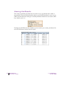
Viewing the Results
The results of optimizing algorithm may be viewed two ways: graphically and in a table of
suggested APs. You may obtain information about a specific AP by placing the cursor over its
symbol. An information box will appear containing information about the exact location, PHY
type, channel, power, etc.
The Suggested AP Table lists the coordinates, power, location, power setting, and channel for
each of the APs that are shown in the floor plan.
26
Aruba RF Plan
v2.0.3 User’s Guide
Part 0500030-01
January 2004
AM Plan
The AM Plan feature calculates the optimum placement for your air monitors (AMs).
Initialize
Initialize the Algorithm by clicking on the Initialize button. This makes an initial placement of
the air monitors and prepares RF Plan for the task of determining the optimum location for
each of the AMs. As soon as you click the Initialize button you will see the AM symbols
appear on the floor plan. Air Monitors are represented by this symbol.
Start
Click on the Start button to launch the optimizing algorithm. You will see the AM symbols
moving on the page as RF Plan finds the optimum location for each.
The process may take several minutes. You may watch the progress on the status bar of your
browser. The algorithm will stop when the movement is less than a threshold value calculated
based on the number of AMs. The threshold value may be seen in the status bar at the bottom
of the browser window.
Viewing the Results
Viewing the results of the AM Plan feature is similar to that for the AP Plan feature.
The results of optimizing algorithm may be viewed two ways: graphically and in a table of suggested AMs. You may obtain information about a specific AP by placing the cursor over its
symbol. An information box will appear containing information about the exact location, PHY
type, channel, power, etc.
The Suggested AP Table lists the coordinates, power, location, power setting, and channel for
each of the APs that are shown in the floor plan.
The Aruba RF Plan Tool
27
RF Plan Tutorial
This section will guide you through the process of creating a building and populating it with
access points and air monitors using RF Plan.
You can use the RF Plan portion of RF Director or you can use the stand-alone Aruba RF
Plan product.
N OTE—If you haven’t yet installed RF Plan, you should do so now. See “Installing RF Plan”
on page 2.
To Launch RF Plan, select Start > All Programs > Aruba Offline RF Plan > Aruba RF Plan.
Our Sample Building
We have filled in the planning table with the information we will use in this tutorial.
Building Dimensions
Height: 100
Width: 100
Number of Floors: 2
User Information
Number of Users:
Users per AP: N/A
Radio Types: a, b, g
Overlap Factor: Medium (150%)
AP Desired Rates
802.11b|g: 48 Mbps
802.11a: 48 Mbps
AM Desired Rates
802.11b|g: 24
802.11a: 24
Don’t Care/Deploy Areas
Shipping & Receiving = Don’t Care
Lobby = Don’t Deploy
28
Aruba RF Plan
v2.0.3 User’s Guide
Part 0500030-01
January 2004
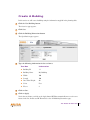
Create A Building
In this section we will create a building using the information supplied in the planning table.
1
Click the New Building button.
The Overview page appears.
2
Click Save.
3
Click the Building Dimension button.
The Specification page appears.
4
Type the following information in the text boxes.
Text Box
Information
z Building ID
1.1
z Building Name
My Building
z Width
100
z Length
100
z Inter Floor Height
20
z Units
Feet
z Floors
2
5
Click on Save.
6
Click on Apply.
Notice that each time you click on the Apply button RF Plan automatically moves to the next
feature in the list. In this case RF Plan moves to the AP Modeling Parameters page.
The Aruba RF Plan Tool
29
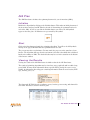
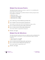
Model the Access Points
You will now determine how many access points are required to cover your building with a
specified data transfer rate and overlap.
In this example we will use the Coverage Model and make the following assumptions about
the performance of our WLAN.
z
z
z
z
Radio Types: a/b/g
Overlap factor: Medium (150%)
802.11a desired rate: 48 Mbps
802.11b desired rate: 48 Mbps
1
Select “801.11 a|b|g” from the Radio Type pull-down box.
2
Select “Medium” from the Overlap Factor pull-down box.
Notice that the percentage show at the left of the pull-down box changes to 150%.
3
Select “48” from the 802.11 b|g Desired Rate pull-down box.
4
Select “48” from the 801.11 a Desired Rate pull-down box.
Notice that the number of required APs has changed to 5.
5
Click Save, then Apply.
Model the Air Monitors
You will now determine how many air monitors are required to provide a specified monitoring
rate. In this example we will continue to use the Coverage Model and make the following
assumptions:
z 802.11 b|g monitor rate: 48 Mbps
z 802.11 a monitor rate: 48 Mbps
1
Select “24” from the 802.11 b|g Monitor Rate pull-down box.
2
Select “24” from the 802.11 a Monitor Rate pull-down box.
Notice that the number of required AMs is now 2.
3
30
Click Save, then Apply.
Aruba RF Plan
v2.0.3 User’s Guide
Part 0500030-01
January 2004
Add and Edit a Floor
You will now add floor plans to your floors and specify “Don’t Deploy” and “Don’t Care”
areas for each floor.
In this section you will:
z Add a background image floor plan for each floor.
z Name the floors.
z Specify any Don’t Deploy and Don’t Care areas.
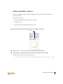
1
Click on the Edit Floor link at the right of the Floor 1 indicator.
Edit Floor Link
2
Type Entrance Level in the Name box of the Floor Editor Dialog.
3
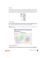
Use the Browse button to locate the background image for the 1st floor.
The file will be located in the following directory:
C:\Program Files\Aruba RF Plan\tutorial\tutorial floor 1.jpg
The Aruba RF Plan Tool
31
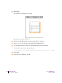
4
Click Apply.
You should see the following type of image:
Repeat the process above for Floor 2.
5
Click on the Edit Floor link at the right of the Floor 2 indicator.
6
Type Second Level in the Name box of the Floor Editor Dialog.
7
Use the Browse button to locate the background image for the 1st floor.
The file will be located in the following directory:
C:\Program Files\Aruba RF Plan\Tutorial\tutorial floor 2.jpg
32
8
Click Apply.
9
Click Save in the Planning window.
Aruba RF Plan
v2.0.3 User’s Guide
Part 0500030-01
January 2004
Defining Areas
Before you advance to the AP and AM Planning pages you will want to define special areas.
In this section you will learn how to define areas where you either do not want to physically
deploy (Don’t Deploy) an AP, or where you don’t care if there is coverage or not.
In this exercise we will assume that we:
z Don’t care if we have coverage in the Shipping and Receiving areas.
z Don’t want to deploy APs or AMs in the Lobby Area
Create A Don’t Care Area
1
Go back to the AP Planning page.
Click on AP Plan in the Feature Tree at the left side of the browser window.
2
Click the “New” link in the Areas box.
The link is located below the lower left corner of the floor plan in the AP Planning window.
This opens the Area Editor.
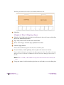
3
Type Shipping and Receiving in the Name text box in the Area Editor.
4
Select “Don’t Care” from the Type pull-down menu box.
5
Click the Apply button.
Notice that an orange box appears near the center of the floor plan.
6
Use your mouse (or other pointing device) to place the cursor over the box.
Notice that the information you typed in the editor appears in the box. You will see the name
and type of area, as well as the coordinates of the lower left corner and upper right corner of
the box.
NOTE—The x = 0 and y = 0 coordinates correspond to the lower left corner of the layout
space.
7
Using your mouse, left-click and drag the box over the Shipping and Receiving area.
Drag one corner of the box to a corresponding corner of the Shipping and Receiving area and
using one of the corner handles of the box, stretch it to fit exactly over the Shipping and
Receiving area.
The Aruba RF Plan Tool
33
Your floor plan with the Don’t Care box should look similar to this:
8
Click Save.
Create A Don’t Deploy Area
1
Click the “New” link in the Areas box located below the lower left corner of the floor
plan in the AP Planning window.
2
Type Lobby in the Name text box in the Area Editor.
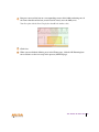
3
Select “Don’t Deploy” from the Type pull-down menu box.
4
Click the Apply button.
Notice that an yellow box appears near the center of the floor plan.
5
Use your mouse (or other pointing device) to place the cursor over the box.
Notice that the information you typed in the editor appears in the box. You will see the name
and type of area, as well as the coordinates of the lower left corner and upper right corner of
the box.
N OTE—The x = 0 and y = 0 coordinates correspond to the lower left corner of the layout
space.
6
34
Using your mouse, left-click and drag the box over the Lobby area on the floor plan.
Aruba RF Plan
v2.0.3 User’s Guide
Part 0500030-01
January 2004
7
Drag one corner of the box to a corresponding corner of the lobby and using one of
the corner handles of the box, stretch it to fit exactly over the lobby area.
Your floor plan with the Don’t Deploy box should look similar to this:
8
Click Save.
9
When you are finished defining area in the Floors page, click the AP Planning button to advance to the next step in the process (AP Plan page).
The Aruba RF Plan Tool
35
Running the AP Plan
In this section you will run the algorithm that searches for the best place to put all your access
points.
You might want to zoom in on the floor plan. Zoom using the Zoom pull-down near the top of
the AP Planning page, or type a zoom factor in the text box at the left of the pull-down and
press the enter key on your keyboard.
Try entering a zoom factor of 400.
Notice that the number of required APs is 5, the same value that you saw when you modeled
your APs above. Notice, also, that none of the APs show on the floor plan yet.
1
Click the Initialize button.
You will see a total of 5 AP symbols appear on the two floor diagrams, 3 on Floor 1 and 2 on
Floor 2. You will also notice that the Suggested Access Points tables below each floor diagram
have been populated with information about the suggested APs for each corresponding floor.
2
Click the Start Button.
After you Initialize the APs you must start the algorithm. You will see the APs move around
on the floor plans as the algorithm is running.
The algorithm will stop when the movement is less than a threshold value calculated based on
the number of APs. The threshold value may be seen in the status bar at the bottom of the
browser window.
N OTE—To see the approximate coverage areas of each of the APs, select an AP type from the
Approx. Coverage pull-down box and select a rate from the Coverage Rate pull-down box.
3
Click Save, then click the AM Planning button.
Running the AM Plan
Running the AM Plan algorithm is exactly like running the AP Plan above.
1
Click on Initialize.
2
Click on Start.
The algorithm will stop when the movement is less than a threshold value calculated
based on the number of AMs. The threshold value may be seen in the status bar at the
bottom of the browser window.
3
36
Click Save.
Aruba RF Plan
v2.0.3 User’s Guide
Part 0500030-01
January 2004