1
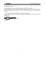
RC802/804-120B*2
Dual 4E1 Modular
Fiber-Optic Multiplexer
(Rev. M)
User Manual
Raisecom Technology Co., Ltd
(04/2005)
Raisecom Technology Co., Ltd
1. Cautions
Please read the following notices carefully before installing and
using the device, Raisecom does not respond to any loss that
caused by violating safety notice.
This series fiber-optic multiplexer is integrated device that has
precise elements, please avoid violent shakes and impacts, and
do not disassemble or maintain the device yourself. If it is
required, please do it under the guide of our technical staff
following in the steps of anti static. Please contact us if there is
any need.
There must be grounding protection for the sake of safety; do
not disassemble the device yourself, we regard it as you waiver
your rights of repair guarantee.
1
Raisecom Technology Co., Ltd
Contents
1.
Cautions ...........................................................................................................................................1
2.
Overview ..........................................................................................................................................3
2.1.
2.2.
2.3.
3.
Parameters.......................................................................................................................................5
3.1.
3.2.
3.3.
4.
Introduction ..............................................................................................................................3
Main Features ..........................................................................................................................3
Part Number Introduction .........................................................................................................3
E1 Interface Specification ........................................................................................................5
Optical Interface Specification..................................................................................................5
Ambience .................................................................................................................................5
How to use .......................................................................................................................................6
4.1.
Introduction of the Front Panel .................................................................................................6
4.2.
DIP-switches Configuration......................................................................................................7
4.2.1.
Dip-switches for E1 Interface Impedance ........................................................................7
4.2.2.
DIP-switch for Function Configuration..............................................................................7
5.
Installation and Test .........................................................................................................................9
5.1.
Inspect after Opening...............................................................................................................9
5.2.
Preparation before Installation .................................................................................................9
5.3.
Installation Procedure ..............................................................................................................9
5.3.1.
Installing the Module into the Chassis..............................................................................9
5.3.2.
Connecting Cables...........................................................................................................9
5.3.3.
Applying the Power Supply ............................................................................................10
5.3.4.
Mask/No Mask Button....................................................................................................10
6.
Appendix A Introduction of Cable Making ......................................................................................12
A.1 E1 Cable ......................................................................................................................................12
2
Raisecom Technology Co., Ltd
2. Overview
2.1. Introduction
RC800-120B series fiber-optic multiplexers are ideal fiber-optic transmission devices for
point-to-point networks, medium-sized and small capacity networks, such as wireless
communication base stations, private communication networks, and switching networks.
The transmission capacity of each optical port is 4 E1 channels.
RC802-120B*2 and RC804-120B* fiber-optic multiplexers can be installed into RC004-16
16-slot chassis to be deployed at the host site. They are usually used to construct the
network at the host site, and working in pairs with standalone RC801-120B or RC805-120B
at the remote site.
2.2. Main Features
•
•
•
•
•
•
•
Very large scale ASIC chips ensures low power consumption; 4-layer PCB ensures
high reliability
Complete alarm indication that can display local and remote alarms simultaneously
Alarm lock and E1 channel loop-back test capabilities implements convenient operation
and maintenance
Provides two independent fiber-optic multiplexer units, each of which provides 1 optical
interface and 4 E1 channels. Each RC802/804-120B*2 module can connect to two
remote multiplexers that may not in the same place. The high integration significantly
saves space.
With modular design, it can be installed into any slot form 1st to 15th.
One modular multiplexer shall correspond to one standalone multiplexer at the remote
site.
Support SNMP management. It can be managed by the network management module
in the MPU slot of RC004-16 chassis. It also supports the management of standalone
multiplexer at the remote site.
2.3. Part Number Introduction
RC800-120B series multiplexers include the following models.
Part Number
Description
RC802-120B*2-S1
RC802-120B*2-S2
RC802-120B*2-S3
RC804-120B*2-S1
Host-site module, dual-unit, 4 E1 and 1 optical port each unit, dual-strand single mode (DSC),
0-25 Km
Host-site module, dual-unit, 4 E1 and 1 optical port each unit, dual-strand single mode (DSC),
10-60 Km
Host-site module, dual-unit, 4 E1 and 1 optical port each unit, dual-strand single mode (DSC),
15-120 Km
Host-site module, dual-unit, 4 E1 and 1 optical port each unit, single strand single mode
(SC-PC), 1310 TX, dual-wavelength, 0-25 Km
3
Raisecom Technology Co., Ltd
RC804-120B*2-S2
RC801-120B-S1
RC801-120B-S2
RC801-120B-S3
RC803-120B-S1
RC803-120B-S2
RC805-120B-S1
RC805-120B-S2
Host-site module, dual-unit, 4 E1 and 1 optical port each unit, single strand single mode
(SC-PC), 1310 TX, dual-wavelength, 10-50 Km
Remote-site standalone, 4 E1, 1 optical port, dual-strand single mode (DSC), 0-25 Km
Remote-site standalone, 4 E1, 1 optical port, dual-strand single mode (DSC), 10-60 Km
Remote-site standalone, 4 E1, 1 optical port, dual-strand single mode (DSC), 15-120 Km
Remote-site standalone, 4 E1, 1 optical port, single strand single mode (SC-PC), 1310
dual-wavelength, 0-25 Km
Remote-site standalone, 4 E1, 1 optical port, single strand single mode (SC-PC), 1310
dual-wavelength, 10-50 Km
Remote-site standalone, 4 E1, 1 optical port, single strand single mode (SC-PC), 1550
dual-wavelength, 0-25 Km
Remote-site standalone, 4 E1, 1 optical port, single strand single mode (SC-PC), 1550
dual-wavelength, 10-50 Km
TX,
TX,
TX,
TX,
The shaded texts in the above table indicate the models that are covered by this manual.
Generally, it is required to add a suffix to the standalone RC801/803/805 series equipment
to indicate the type of power supply. For example, RC801-120B-S1/AC indicates AC 220V
power supply; RC801-120B-S1/DC indicates DC -48V power supply.
When interconnecting the fiber-optic multiplexers, it is suggested that follow the rules below.
The modular multiplexer shall be installed into host-site chassis.
Host-site
module
or Remote-site module
standalone
RC802-120B*2-S1
Two RC801-120B-S1
RC802-120B*2-S2
Two RC801-120B-S2
RC802-120B*2-S3
Two RC801-120B-S3
RC804-120B*2-S1
Two RC805-120B-S1
RC804-120B*2-S2
Two RC805-120B-S2
Note: the above interconnection rules are the most common ones that modular multiplexers
work in pairs with standalone versions. The host-site network management module can
globally manage the host-site modular and remote-site standalone multiplexers.
When both host-site and remote-site are modular multiplexers, they can work normally but
without remote management capability.
When both host-site and remote-site are standalone multiplexers, they can work normally
with remote management capability.
4
Raisecom Technology Co., Ltd
3. Parameters
3.1. E1 Interface Specification
Bit rate:
2048Kbps±50ppm
Line code:
HDB3
Impedance of interface:
75Ω (unbalanced) or 120Ω (balanced)
Electrical characteristics:
complies with ITU-T G.703
Transfer characteristics:
complies with ITU-T G.823, G.724
Input jitter tolerance:
complies with ITU-T G.823, G.724
3.2. Optical Interface Specification
Bit rate:
Line code:
Fiber connector:
100Mbps
4B5B
SC
Part Number
Connector
Type
Wavelength
(nm)
Launch
Power
(dBmW)
Receiving
Sensitivity
(dBmW)
Transmission
Distance
(Km)
Link Loss
(dB/Km)
RC802-120B*2-S1
RC802-120B*2-S2
RC802-120B*2-S3
RC804-120B*2-S1
RC804-120B*2-S2
DSC
DSC
DSC
SC/PC
SC/PC
1310
1310
1550/DFB
1310
1310
-15 ~ -8
-5 ~ 0
-5 ~ 0
-12 ~ -3
-5 ~ 0
-34
-34
-36
-30
-32
0 ~ 25
10 ~ 60
15 ~ 120
0 ~ 25
10 ~ 50
0.5
0.5
0.25
0.5
0.5
RC804 series are equipped with single strand dual-wavelength optical ports. The “1310nm”
is the TX wavelength, and the RX wavelength is “1550nm”
3.3. Ambience
Working temperature: 0 ~ 45℃
Humidity:
≤ 90% (25℃)
5
Raisecom Technology Co., Ltd
4. How to use
4.1. Introduction of the Front Panel
Fixing Handle
Power (Green), ON when works properly
L line indicates local alarms, R for remote alarms
E1 LOS alarms (Red): ON when loss of signal in E1 channels
First Unit
LOS optical alarm (Red): ON when loss of signal in optical link
ERR alarm (Yellow): ON when receiving error occurs. The
detailed alarm reasons, including LOF, 10-3 BER, and 10-6 BER
can be viewed in network management software.
Fiber connector: DSC/PC for dual-strand fiber, TX for transmit and RX
for receive; SC/PC for single strand fiber
Second Unit. The definitions are the same as the
first unit.
Mask fake alarm button:
Push-in, mask E1 fake alarms; push out, unmask.
Valid for both Unit 1 and Unit 2
Fixing Handle
Figure 1. Sketch of RC802-120B*2, RC804-120B*2 front panel
The front panel includes the indications of E1 receiving signal loss alarms and optical
alarms. All the alarms are for the receiving link (signal input). The Line L indicates the
alarms generated at the local site and Line R at the remote site. The remote alarms are
sent through the optical link, so that they are accurate only when the optical receiving is
6
Raisecom Technology Co., Ltd
working in good condition.
4.2. DIP-switches Configuration
4.2.1. Dip-switches for E1 Interface Impedance
There are 8 groups of 4-bit dip-switches, UP1 to Up4 and DW1 to DW4.
These switches cannot be managed by network management software,
so they must be set manually.
ON
OFF
1234
Definition as shown below
1st
2nd
3rd
4th
1st
2nd
3rd
4th
ON
ON
ON
OFF
Or
OFF
OFF
OFF
ON
75Ω unbalanced signal effective
120Ω balanced signal effective
As shown in figure above, the default status is set as “75Ω unbalanced signal BNC
interface effective”.
• When adopting 75 Ohm unbalanced signal, it is required to plug a DB37 to 8 CC3
coaxial adapter, which is of CC4B-8G type. This adapter can convert DB37 connector
to 8 CC3 coaxial connectors, for input and output of 4 E1 channels.
• When adopting 120 Ohm balanced signal, it is required to first set the dip-switches as
per the above tables. 37-pin connector shall be used to connect the twisted-pair cables
for DB37 connector. Please refer to Appendix A for details of sequence of twisted-pair
and cable making.
4.2.2. DIP-switch for Function Configuration
There are two 6-bit dip-switches, SW1 and SW2 on the PCB. SW1
is for the configuration of Unit 1, and SW2 for Unit 2.
•
1st ~ 4th: Loop-back control
1st bit
2nd bit
OFF
OFF
ON
OFF
3rd bit
OFF
4th bit
OFF
123456
Loop-back
No
loop-back
OFF
OFF
OFF
ON
1st E1
OFF
OFF
ON
OFF
2nd E1
OFF
OFF
ON
ON
3rd E1
OFF
ON
OFF
OFF
4th E1
ON
ON
ON
ON
All E1 links
Note: Only two test method can be set: single E1 channel loop-back or all E1 channels
loop-back. When single E1 channel loop-back is testing, the other channels are working
normally without disturbance.
The network management software can send out the loop-back enable/disable command,
and they have high priority to the settings by hardware. Usually, users are advised to set
loop-back by network management software for convenience.
• 5th bit: loop-back type options
This switch is used to choose “remote loop-back” or “local loop-back” when performing
the E1 loop-back operations.
7
Raisecom Technology Co., Ltd
5th bit
OFF
ON
Loop-back type option
Remote loop-back enable
Local loop-back enable
Fiber
BER tester
Multipl
exer
Multipl
exer
E1
E1
Local
Remote
Figure2: sketch map of setting remote loop-back on local site
Fiber
BER tester
Multipl
exer
Multipl
exer
E1
E1
Remote
Local
Figure3: sketch map of setting local loop-back on local site
Note: When any loop-back is set on local site, 1st ~ 4th loop- back DIP-switch of remote site
must be all off (not loop-back).
The default status of this switch is “enable loop-back”. This switch cannot be viewed or
controlled by network management software. When setting loop-back test by software, first
ensure the switch is in default status.
•
6th bit: Fault-Pass-Through capability switch
When FPT is disabled, it’s similar to AIS of traditional multiplexers. When E1 signal on
remote site is lost, the E1 output opposite of local site is “1”; when optical signal at local site
is lost, all E1 output are “1” on local site.
FPT enable: when there is alarm of LOS on any direction of optical interface, both sides E1
output can not transmit HDB3 coding. At this circumstance, alarm on terminal device (such
as switches, converters, SDH) of E1 link will be LOS, not AIS alarm.
6th bit
FPT
OFF
Disable (complies with AIS)
ON
Enable
This function is for some special need. It can be inquired, but can’t be controlled. So if it is
required to start, it must be forced manually.
8
Raisecom Technology Co., Ltd
5. Installation and Test
5.1. Inspect after Opening
Please first check if the models and part numbers are in consistence, and also check if the
equipments are damaged.
5.2. Preparation before Installation
z
z
z
z
z
z
z
Carefully read this manual
Prepare all kinds of the cable. Ensure that they are not short-circuited. Refer to
Appendix A for cable making.
Ensure RC004-16 is properly installed, and the chassis is well connected with the
ground.
Prepare the BERT and optical power meter for test of line quality.
Change the dip-switch setting on the bottom panel if 120 Ohm balanced signal interface
is required.
Set up the fault-pass-through enabled if using the function.
This module does not support hot-swapping
5.3. Installation Procedure
5.3.1. Installing the Module into the Chassis
Insert the module into any service slot from 1st to 15th, with PWR indicator upside. The MPU
slot is particular for the network management module, thus cannot be inserted with service
modules.
Installing fiber-optic multiplexer in MPU slot will cause damage to the module itself or the
back panel of the chassis.
5.3.2. Connecting Cables
z E1 port
The upside of RC004-16 chassis, corresponding to fiber-optic module, has 2 groups of
DB37 male interfaces. The upper one is for the 1st – 4th E1 channels of Unit 1, and the lower
one for the 1st – 4th E1 channels of Unit 2.
It is suggested that users use SYV75-2-2 coaxial cables to connect the BNC connector.
Users can connect a CC4B-8G adapter on DB37 male interface to connect CC3-K3 coaxial
cables.
If using 120 Ohm balanced interface, users can connect the DB37 male interface with
DB37 female-connector twisted-pair.
z Optical interface
Plug the SC fiber tail into optical interface (push hard until to the deep end). If not sure
about transmission direction, it’s advised first to turn on the power of device and then plug
9
Raisecom Technology Co., Ltd
in the fiber cable.
5.3.3. Applying the Power Supply
When PS is turned on, the PWR indicator shall be on.
After applying the power supply, first please ensure there is no alarm at the optical port. If
the optical port is connected properly, there shall not be LOS alarm. When just applying the
power supply, the ERR (yellow) indicator shall be on. This is because of the few error bits
generated by the jitters. It shall be out after 10 – 20 seconds. The ERR indicator includes 3
kinds of alarms, Loss of Frame, BER exceeding 10-3, and BER exceeding 10-6. Please refer
to network management software for details.
5.3.4. Mask/No Mask Button
If the connected E1 links are working in good condition without any signal loss, while there
is still another unused E1 link, the LOS alarm for unused E1 link may occur, which is called
“unused E1 alarm”. Press MASK/NO MASK button “on” to clear all the unused E1 alarm
and all the E1 LOS alarm indicators will be off.
In the case unused E1 link alarm being masked, if the connected E1 sub-channel is
disconnected, the LOS indicator of this sub-channel will still be on.
If power supply is cut off and turned on again, then the mask function will be disabled.
Press button to “off” and then pressed to “on” again.
If after a period of operation, a new E1channel is needed, first disable the mask function
and then connect E1 link.
Chapter 4 Troubleshooting
If there are any problems during installation and using, try the following proposals. If the
problems still can not be solved, please contact distributors/agents for help.
The following explanations and solutions for alarms at optical ports and LOS alarms at E1
ports are used to handling local alarm problems. For remote-end alarms, please handle
them at remote site.
z PWR (green) indicator not on
Answer: PS faults or PWR indicator is not functioning. Check the power supply of
RC004-16.
z LOS (red) indicator of optical port is on
Answer: Loss of receiving signal occurs at optical port. Check whether the input fiber (RX)
is connected well and ensure not reversed. Or check the receiving optical power with
optical power test-meter; it should be greater than receiving sensitivity specification.
z ERR (yellow) indicator of optical interface is on
Answer: When just connecting the fiber-optic cable, the ERR (yellow) indicator shall be on.
This is because of the few error bits generated by the jitters. It shall be out after 10 – 20
seconds. The ERR indicator includes 3 kinds of alarms, Loss of Frame, BER exceeding
10-3, and BER exceeding 10-6. Please refer to network management software for details.
z LOS (red) indicator of E1 sub-channel is on
Answer: Loss alarm of RX signal at E1 sub-channel, no HDB3 signal is received. Check
whether all E1 ports are connected well, or whether 75Ω cables are reversely connected, or
whether the wires of 120Ω cables are in correct sequence. If LOS alarm occurs at unused
10
Raisecom Technology Co., Ltd
E1 sub-channel, press “mask” button to “on” to musk the alarm after finishing the
configuration of device.
z Mask button is on, but there is still alarm in unused E1 sub-channel.
Answer: probably the mask function is disabled if power supply is cut off and then turned on.
To solve is by pressing the mask button to “OFF”, and then pressing to “on” to enable mask
function.
• How to unplug the coaxial cable from the coaxial connector.
Answer: push the thickest part of the connector without turning, and then pull out the
coaxial cable.
11
Raisecom Technology Co., Ltd
6. Appendix A Introduction of Cable Making
A.1 E1 Cable
• 75 Ohm signal adopts DB37 coaxial adapter:
SYV 75-2-2 coax cable, the distance shall not be longer than 200m.
First pick out the CC3-K3 connector from the accessories, and release the tail protecting
jack. Secondly, separate the core from the shield, and put the tail protecting jack on it.
Solder the strand with the core of the CC3-K3 connector. Solder the cable shield with the
shield of the CC3-K3 connector. Finally, fix the jack at the end of the connector.
•
120 Ohm signal adopts DB37 male connector:
DB37 Pin
1st Channel 2nd Channel 3rd Channel
Definition
OUT
3, 4
7, 8
11, 12
IN
21, 22
25, 26
29, 30
Others - GND
12
4th Channel
15, 16
33, 34
Raisecom Technology Co., Ltd
@2005 Raisecom Technology Co., Ltd.
All trademarks are the property of their respective owners.
Technical information may be subject to change without prior notification.
13