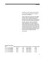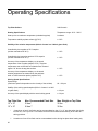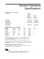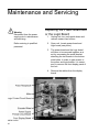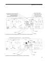
1
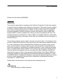
BARNSTEAD|THERMOLYNE
MIRAK™
4-Place Stirrers and
Stirring Hot Plates
OPERATION MANUAL AND PARTS LIST
SERIES 846, 847
Model #
S73130
S73130-26
S73134
S73135
SP3230
SP73230-26
SP73235
SP73235-60
SP73238
SP73238-60
Voltage
240
220-240
100
120
240
220-240
120
120
208
208
Description
12x12
12x12
12x12
12x12
12x12
12x12
12x12
12x12
12x12
12x12
LT847X2 • 5/28/99
1
Table of Contents
Safety Information ..............................................................................................................................................3
Alert Signals..................................................................................................................................................3
Warnings ......................................................................................................................................................3
Introduction..........................................................................................................................................................6
Unpacking ..........................................................................................................................................................7
Installation ..........................................................................................................................................................8
Principles of Operation......................................................................................................................................10
Operation ..........................................................................................................................................................12
Removing the Clear Plastic Cover..............................................................................................................12
The Power Switch ......................................................................................................................................12
Setting the Stirring Speed ..........................................................................................................................13
Stirring Speed Guide ..................................................................................................................................14
Setting the Temperature ............................................................................................................................14
Controlling Top Plate Temperature ............................................................................................................16
Controlling Solution Temperature ..............................................................................................................16
Using the Probe with the Temperature Display for Stirring Applications Only............................................17
To Achieve Fast Heat-up of Large Volumes ..............................................................................................17
Heating Small Volumes ..............................................................................................................................18
Heating Metal Vessels and Sand Baths ....................................................................................................18
Heat-up Time Guide....................................................................................................................................19
Operating Specifications ..................................................................................................................................20
Heating Specifications ................................................................................................................................20
Stirring Speed Specifications......................................................................................................................20
General Operating Specifications ....................................................................................................................21
Dimensions........................................................................................................................................................21
Electrical Ratings ..............................................................................................................................................21
Temperature Range for Hot Plates and Stirring Hot Plates........................................................................21
Stirring Speed Range fro 4-Place Stirrers and Stirring Hot Plates ............................................................21
Environmental Parameters for all Units ......................................................................................................21
Maintenance and Servicing ..............................................................................................................................22
Replacing the Power Board and/or the Logic Board ..................................................................................22
Replacing the Display Board ......................................................................................................................24
Replacing the Motors..................................................................................................................................26
Replacing the Top Plate Assembly ............................................................................................................28
Set-up Procedure........................................................................................................................................31
Calibrating the Probe Temperature Input....................................................................................................33
Troubleshooting ................................................................................................................................................35
Exploded Views ................................................................................................................................................36
Replacement Parts............................................................................................................................................38
Ordering Procedures ........................................................................................................................................39
One Year Limited Warranty ..............................................................................................................................40
2
Safety Information
Alert Signals
Warning
Warnings alert you to a
possibility of personal injury.
Caution
Cautions alert you to a
possibility of damage to the
equipment.
Note
Notes alert you to pertinent facts
and conditions.
Hot Surface
Hot surfaces alert you to a
possibility of personal injury if you
come in contact with a
surface during use or for a
period of time after use.
Your Thermolyne MIRAK™ 4-Place stirring
hot plate has been designed with function,
reliability and safety in mind. It is the user’s
responsibility to install it in conformance with
local electrical codes.
This manual contains important operating and
safety information. The user must carefully
read and understand the contents of the manual prior to the use of this equipment.
Warnings
To avoid electrical shock, always:
1. Use a properly grounded electrical
outlet of correct voltage and current
handling capacity.
2.
Disconnect from the power supply
prior to maintenance and servicing.
To avoid personal injury:
1. Do not use in the presence of flammable or combustible materials; fire
or explosion may result. This device
contains components which may
ignite such materials.
2.
Keep top surface clean. Use a nonabrasive cleaner. Alkali spills, hydrofluoric acid spills or phosphoric acid
spills may damage top and lead to
thermal failure. Unplug unit and
remove spills promptly. Do not
immerse unit for cleaning.
3.
Replace the top immediately if damaged by etching, scratching or chipping. A damaged top can break in
use.
3
SAFETY INFORMATION
Caution
Space unit 12 inches away from
combustible materials under any
conditions.
Gross weight of items placed on
top of 12”x 12” stirrers and stirring hot plates should not
exceed 30 lbs.
4
4.
Do not remove or modify grounded
power plug. Use only properly grounded
outlets to avoid shock hazard. Not rated
for use in hazardous atmospheres.
5.
Use caution when heating volatile materials; top surface and element can reach
the “Flash Point Temperature” of many
chemicals. These stirrers and stirring
hot plates are not explosion proof. Fire
or explosion may result. Unit contains
components which may ignite such
materials.
6.
Use appropriate hand and eye protection when handling hazardous chemicals.
7.
Caution: Hot Surface. Avoid Contact.
The hot plate will remain dangerously
hot with no visible indication for some
time after use.
8.
Do not use in highly corrosive atmospheres; corrosive fumes and spill may
damage top and internal components,
creating a shock hazard.
9.
Refer servicing to qualified personnel.
SAFETY INFORMATION
Please note the following WARNINGS:
Warning
This warning is presented for compliance with California Proposition 65 and other regulatory agencies and only applies to the insulation in this product. This product contains refractory ceramic, refractory ceramic fiber or fiberglass insulation, which can produce respirable
dust or fibers during disassembly. Dust or fibers can cause irritation and can aggravate
preexisting respiratory diseases. Refractory ceramic and refractory ceramic fibers (after
reaching 1000°C) contain crystalline silica, which can cause lung damage (silicosis). The
International Agency for Research on Cancer (IARC) has classified refractory ceramic fiber
and fiberglass as possibly carcinogenic (Group 2B), and crystalline silica as carcinogenic to
humans (Group 1).
The insulating materials can be located in the door, the hearth collar, in the chamber of the
product or under the hot plate top. Tests performed by the manufacturer indicate that there
is no risk of exposure to dust or respirable fibers resulting from operation of this product
under normal conditions. However, there may be a risk of exposure to respirable dust or
fibers when repairing or maintaining the insulating materials, or when otherwise disturbing
them in a manner which causes release of dust or fibers. By using proper handling procedures and protective equipment you can work safely with these insulating materials and
minimize any exposure. Refer to the appropriate Material Safety Data Sheets (MSDS) for
information regarding proper handling and recommended protective equipment. For additional MSDS copies, or additional information concerning the handling of refractory ceramic
products, please contact the Customer Service Department at Barnstead|Thermolyne
Corporation at 1-800-553-0039.
Please read all the information in this manual before operating the unit.
Warning
Refer servicing to qualified personnel.
5
Introduction
Your Thermolyne MIRAK™ 4-place stirrer or
stirring hot plate is a general purpose stirring or
stirring and heating plate designed for laboratory procedures requiring precise control of temperature and/or stirring speed. Each 4-place
MIRAK model includes a digital display for monitoring actual stirring speed, and the stirring hot
plate models have dual displays so temperature
and stirring speed can be monitored simultaneously. The 4-place stirring hot plate is capable of
producing accurately controlled temperatures
from 40°C through 540°C on all 208 volt and
240 volt models. 120 volt models have a temperature range of 40°C to 370°C. The temperature may be controlled at the plate surface by
internal Type K thermocouple sensor, or the
solution temperature may be controlled utilizing
an accessory ungrounded Type K thermocouple
probe. A 6” or 10” general purpose stainless
steel immersion probe or chemical-resistant 7”
solid Teflon® immersion probe may be ordered
separately. The stirrer will accurately maintain
stirring speeds from 60 rpm up to 1200 rpm. On
stirring hot plate models, the accessory probe
may also be utilized to display the actual temperature of heat-sensitive solutions during
stirring-only functions. The top plate on the
MIRAK 4-place units is solid ceramic and is suitable for use with glass or metal vessels.
Your MIRAK 4-place stirrer or stirring hot plate
may be used for general purpose heating applications and/or general laboratory mixing of solutions including; sample preparation, heating
reagents, melting paraffin, warming resinous
chemicals, content analysis, solvent evaporations, digestions, media preparation and sterilization, titrations, sand baths and microscale
chemistry applications.
6
Unpacking
Note
A special 20-amp cordset is
included on the CSA-approved
model of the 12” x 12” 120 volt
MIRAK 4-place stirring hot plate
(SP73235). This 20-amp cordset
can only be plugged into a nonstandard 20-amp, 120 volt wall
receptacle. If you do not have the
appropriate receptacle, contact a
qualified electrician for installation
of a 20-amp 120 volt outlet.
1.
Remove your MIRAK 4-place stirrer
or stirring hot plate from the carton.
2.
Inspect to ensure that the unit has not
been damaged during shipment.
3.
If the unit appears to have sustained
shipping damage, contact the distributor from whom you purchased this
product or call Barnstead|Thermolyne
Customer Service at 800-553-0039.
4.
Remove the packaging from underneath the top plate by gently pulling
the packaging material toward you.
A 12” x 12” 120 volt MIRAK 4place stirring hot plate (SP7323560) is available with a standard
15-amp, 120 volt cordset.This
model is not CSA-approved.
7
Installation
8
1.
Set the unit on a flat, stable surface at
least 12” away from combustible materials and plug the cordset into a properly
grounded electrical outlet of correct voltage and current handling capacity
2.
Use your right hand to locate the
ON/OFF power switch which is on the
side, near the front right corner as you
face the unit.
3.
Press the black ON/OFF power rocker
switch to the ON position. The red LED
display(s), and the green power light to
the left of the display(s) should illuminate. The unit is ready for operation.
INSTALLATION
Front View
Back View
9
Principles of Operation
Each MIRAK unit utilizes the latest in microprocessor technology to deliver the most reliable, accurately controlled, ceramic top hot
plate, stirrer and stirring hot plate on the market.
Your MIRAK 4-place 240 volt and 208 volt stirring hot plate has an electronic closed loop
feedback control which will accurately maintain
temperature setpoints from 40°C to 540°C. The
120 volt MIRAK 4-place stirring hot plate will
maintain temperature setpoints from 40°C 370°C. The top plate surface temperatures are
calibrated and verified at the factory using the
latest in infrared temperature measurement. The
measurements are made with an infrared meter
mounted approximately 26” above the top surface of the hot plate or stirring hot plate. If the
temperature measurement of the ceramic top is
made with measurement devices other than the
infrared, the error of the measuring technique
may be greater than the error of the unit.
The MIRAK stirring Hot Plate units use an
ungrounded Type K thermocouple for measuring
both the top plate temperature and the solution
temperature when using the probe. Both top
plate surface and probe temperature are measured with independent analog circuits. This provides a significant increase in certain types of
metal vessels and sandbaths on the MIRAK
without damaging the ceramic top. However, we
recommend that you do not control the temperature with a probe when heating a metal vessel
or a sandbath.
The electronic stirring speed control on 4-place
MIRAK units will maintain the speed setpoint
when the unit is loaded at ±4 rpm as displayed
by the LED display on the unit. There are four
10
PRINCIPLES
OF
OPERATION
individual motors in the MIRAK 4-place stirrers and stirring hot plates which produce
maximum stirring torque under normal laboratory load conditions. Each motor is combined
with a powerful magnet to provide exceptional
magnetic coupling with a stirbar. Each motor
is centered beneath each of the four stirring
positions indicated by the circles silkscreened
on the 12” x 12” top plate. All four motors will
operate at the same speed.
11
Operation
Removing the Clear Plastic
Cover
Your MIRAK unit has a protective plastic cover
over the front control panel. This plastic cover is
designed to protect the control knobs and the
display panel from spills, and should remain in
place when the unit is being used. To use the
knob(s) while the plastic cover is in place, spin
the knob(s) from the bottom where the knob
projects below the plastic cover. This plastic
cover can be easily removed for cleaning by
grasping the cover at each bottom corner and
gently pulling the sides of the plastic cover away
from the case while lifting the cover toward you.
To replace the cover simply slide it back onto
the case.
The Power Switch
Your MIRAK unit has a separate ON/OFF power
switch which is a black rocker switch located on
the lower front corner of the right side as you’re
facing the unit. This separate power switch
allows you to turn your MIRAK hot plate, stirrer
or stirring hot plate on or off without disturbing
your temperature and/or speed setting. Your last
setpoint will be held in memory even if the unit
is unplugged and will reappear on the display as
soon as the unit is powered up again.
Whenever the power is on, a green power light
illuminates on the front control panel.
12
OPERATION
Setting the Stirring Speed
The 12” x 12” top plate will accommodate up
to four 1 liter vessels, one at each stirring
position. The 4-place MIRAK will also stir two
2 liter flasks simultaneously with up to two 1
liter flasks, one at each of the other two stirring positions. Actual stirring speed may differ
between larger vessels and smaller vessels
stirred simultaneously, depending on the
amount and the viscosity of the solution in
each flask.
Your MIRAK 4-place stirrer or stirring hot
plate has an electronic feedback speed control which will maintain a precise speed setpoint from 60 rpm to 1200 rpm with accuracy
of ±2 rpm. Maximum speed at each position
is dependent on viscosity of the solution
and/or the amount of solution in each vessel.
The MIRAK stirrers and stirring hot plates are
equipped with a strong magnet and high
torque motor which will draw a vortex in up to
1800 ml of water stirred in a 2 liter flask with
a new 2” stir bar.
To set the speed, spin the SPEED CONTROL
knob until your desired setting is indicated on
the digital display. As you move the knob, the
SET light next to the RPM display will illuminate. Turn the knob clockwise to increase the
speed or counterclockwise to decrease the
speed. The unit will not start to stir until you
press the speed control knob. Once the unit
begins stirring, the display will register ACTUAL speed and the SET light will no longer be
illuminated. To check your setpoint, move the
knob counterclockwise one position. You will
feel a click, the SET light will illuminate and
your setpoint will be displayed again for five
13
OPERATION
seconds. After five seconds the display will
automatically return to indicating actual speed
and the SET light will go out. To stop the stirring
action without changing your setpoint, press the
knob once. To resume stirring at the set speed,
press the knob again.
If you want to ensure that the unit will not start
to stir if the knob is inadvertently pressed, turn
the speed control knob until the display indicates the word OFF.
Setting the Temperature
Your MIRAK 4-place stirring hot plate has an
electronic closed-loop feedback control which
will accurately maintain temperature setpoints
from 40°C through 540°Con the 240 volt and
208 volt models. The 240 volt 4-place stirring
hot plates will maintain temperatures from 40°C
through 370°C. An unloaded stirring hotplate will
heat to maximum temperature in just 8 minutes.
A HOT light on the front panel will illuminate
whenever the top surface temperature exceeds
50°C. The temperature may be controlled either
at the top plate by the internal Type K thermocouple sensor, or in the solution using an accessory ungrounded Type K thermocouple probe.
(A 6” or 10” stainless steel general purpose
Stirring Speed Guide
Unit
4-place
4-place
4-place
4-place
Flask Size
MIRAK
MIRAK
MIRAK
MIRAK
1 liter
2 liter
1 liter
500 ml
Stirbar Size
2”
2”
2”
2”
Amount of
Solution
800 ml
1800 ml
1000 ml
350 ml
Viscosity
Maximum Speed*
water
water
cooking oil
30 wt. motor oil
* Maximum speed obtained without the stir bar loosing coupling with the magnet.
(For speed stability and display accuracy please refer to the Operating Specifications.)
14
1200 rpm
1200 rpm
700 rpm
1100 rpm
OPERATION
immersion probe or a chemical-resistant 7”
Teflon immersion probe are available through
you distributor, or by contacting
Barnstead|Thermolyne at 800-553-0039.)
Your MIRAK 4-place stirrer or stirring hot
plate will accept any ungrounded Type K thermocouple probe, however, the accuracy of
probes other than those we’ve tested and
specified may exceed the probe accuracy rating we’ve designated.
Note
The temperature display will not
indicate a temperature less than
40°C. If the actual temperature is
less than 40°C, the word LO will
be indicated until the actual temperature reaches 40°C.
Warning
Caution: Hot Surface. Avoid
Contact. The hot plate will remain
dangerously hot with no visible
indication for some time after use.
Your MIRAK 4-place stirring hot plate will display the temperature in °C. The display will
always indicate OFF or your last setpoint, and
the SET light will be illuminated until you
press the heat control knob to initiate operation. Once the heat control knob has been
pressed, the ACTUAL temperature of the top
plate or the probe will be displayed and the
SET light will no longer be illuminated. If you
want to check your setpoint, you do not have
to press the knob again; simply turn the knob
counterclockwise one click. Your setpoint will
be displayed for approximately five seconds
until the display returns to indicating the actual temperature.
A single element covers the entire surface of
the 12” x 12” top plate and supplies even heat
to the entire surface. A single large vessel or
numerous smaller vessels can be heated anywhere on the top plate when the stirring function is not in use. Vessels to be heated only
do not have to be located at the center of
each silkscreen position.
If you want to ensure that the unit will not
heat if the knob is inadvertently pressed, turn
the temperature control knob until the display
indicates the word OFF.
15
OPERATION
Controlling Top Plate
Temperature
Your MIRAK 4-place stirring hot plate will control
the top plate, and the display will indicate top
plate temperature WHENEVER THE PROBE IS
NOT PLUGGED IN. When the unit is displaying
the top plate temperature the word TOP on the
front panel will be illuminated.
Note
The top plate temperatures will
be higher than your solution
temperature.
Warning
If the probe is plugged into your
4-place stirring hot plate while
the heat control is operating but
is not in solution, the temperature display will continue to indicate an ambient temperature.
Because the setpoint cannot be
reached, the element will continue to supply heat to the top
plate, and the maximum top
plate temperature of 540°C may
be reached.
When using the probe accessory, make sure the probe is
always in the solution when the
heat control is operating. (Any
Type K thermocouple used must
be an ungrounded type.
Note
The top plate temperature will
not exceed 540C.
16
Controlling Solution
Temperature
To control your solution temperature simply plug
an ungrounded Type K thermocouple probe into
the single probe receptacle located on the back
of the unit and place the probe in your solution.
The display will indicate the actual temperature
of the solution as measured by the probe, and
the word PROBE on the front panel will be illuminated.
The solution probe offers more exact temperature control than regulating the top plate by the
thermal internal sensor. If you need to maintain
a precise setpoint, we recommend using a
probe to control the solution temperature
instead of controlling the top plate temperature.
When using a probe with your MIRAK 4-place
stirring hot plate, it is recommended that you
use a clamp on a support rod to hold the probe
in your solution.
To ensure accurate probe readings, as much of
the probe sheath as possible should be
immersed in your solution.
OPERATION
To obtain an accurate reading when you are
using the probe and stirring your solution,
make sure the probe is immersed in the liquid
and is not located in air in the center of the
stirring vortex.
Using the Probe with the
Temperature Display for
Stirring-only Applications
On the stirring hot plate model, the probe can
also be utilized to monitor the actual temperature of your solution when you want to stir the
solution without heating. To use the probe
without heating the solution, turn the knob
until the display indicates OFF and press the
knob to initiate operation. The element will not
supply heat to the hot plate. The display will
indicate LO if your solution temperature
remains at less than 40°C, or the actual temperature of your solution if it is above 40°C.
To Achieve Fast Heat-up of
Large Volumes
With a Probe
When heating large volumes of solution, preheat the top plate at maximum temperature to
allow the plate to heat the solution quickly
before plugging your probe into the probe
receptacle in the back of the unit. As the top
plate heats, monitor your solution temperature
with a standard laboratory thermometer until
your solution is approximately 15° below your
17
OPERATION
desired setpoint. Now plug your probe into the
unit, change the setpoint to your desired solution temperature, and place the probe in your
solution.
Without a Probe
Note
If you allow the top plate to
reach the maximum temperature of 540°C while preheating
and then turn the control down
to a setpoint less than 200°C,
the temperature of the top will
drop rapidly to 200°C. Because
of the natural cooling characteristics of ceramic, the temperature of the top will drop much
more gradually after the top
plate temperature reaches
200°C.
If you are heating larger volumes and do not
intend to use the probe to maintain a precise
solution temperature, faster heating can be
achieved by turning the heat control knob to
maximum temperature until the solution starts to
heat, and then turning the setpoint back to your
desired top plate temperature.
Heating Small Volumes
To heat small volumes quickly it should not be
necessary to preheat the solution at a higher
temperature. By not preheating small volumes
you avoid the potential for the temperature to
overshoot your desired setpoint. If you plan to
control the solution temperature of a small volume sample with the probe, initiate heating with
the probe in the solution; no preheating should
be required.
Heating Metal Vessels and
Sand Baths
Metal vessels and sand baths cannot be heated
on most solid ceramic tops because of the tendency for the metal and the sand to reflect heat
back into the top, eventually exceeding the
maximum temperature rating for a ceramic top,
which causes it to break. Because the
advanced electronic control in the MIRAK is
capable of precisely regulating the top plate
18
OPERATION
temperature, metal vessels and sand baths
may be heated safely without the danger of
the ceramic top breaking.
When heating metal vessels and sand baths
however, we recommend that you DO NOT
use the probe to control the temperature.
Because of the heating and cooling properties
of metal and sand, the sample temperatures
fluctuate, which will result in unstable top
plate temperatures. We achieved better
results controlling the top plate temperature,
which allowed us to maintain a constant level
of heat to the sand bath or metal vessel. The
top plate setpoint should be set approximately
100° above the temperature required for your
sample, and the sample temperature may be
monitored with a standard laboratory
thermometer.
Heat-up Time Guide
Unit
12” x
12” x
12” x
12” x
12” x
12” x
12”
12”
12”
12”
12”
12”
120
120
120
120
120
120
volt
volt
volt
volt
volt
volt
MIRAK
MIRAK
MIRAK
MIRAK
MIRAK
MIRAK
Temperature Setpoint Flask Size Amount of Solution Time to Vigorous Boil
540°C
1 liter
1000 ml (water)
26 min.
540°C
2 liter
1800 ml (water)
32 min.
540°C
4 liter
4000 ml (water)
46 min.
540°C
1 liter
1000 ml (water)
17 min.
540°C
2 liter
1800 ml (water)
21 min.
540°C
4 liter
4000 ml (water)
25 min.
19
Operating Specifications
Top Plate Surface
Solid Ceramic
Heating Specifications
Temperature range: 40°C - 540°C
Heat-up time to maximum temperature (unloaded top plate)
8 minutes
Temperature stability at plate surface (@ 70°C)
± 2.0°C
Stability of the solution temperature (400 ml of water in a 1000 ml glass flask):
Controlled by the top plate at 70°C setpoint
(solution maintained at 30°C)
± 1.0°C
Controlled by the immersion probe at 70°C setpoint
(solution maintained at 70°C)
± 1.0°C
Accuracy of the temperature display vs. the actual
temperature of the hot plate (setpoint 70°C). Top plate
temperature was verified with an infrared meter mounted
approx. 26” above the top plate surface
± 1.0°C
Accuracy of the temperature display vs. the actual
solution temperature as measured by the stainless
steel or Teflon immersion probe (setpoint 70°C)
± 1.5°C
Stirring Speed Specifications
Speed range
(maximum speed is dependent on the viscosity of the solution)
60 - 120 rpm
Stability of the stirring speed setpoint (600 ml of water in a 1000
ml glass flask)
± 4.0 rpm
Accuracy of the speed display with the actual stirring speed
± 2.0 rpm
Top Plate Size
12” x 12”
12” x 12”
Max. Weight on Top Plate
30 lbs.
30 lbs.
20
Max. Recommended Flask Size
2 liters*
6 liters**
*
A maximum of two 2 liter flasks can be accommodated on the 12” x 12” top plate when the stirring
function is in use. Up to two 1 liter flasks can be accommodated simultaneously at the other two
stirring positions.
**
A maximum of one 6 liter flask can be accommodated on the stirring hot plate when heating only.
General Operating
Specifications
Dimensions - 12” x12” models
Model Numbers
Overall Width
Overall Height
Overall Depth
Top Plate Width
Top Plate Height
Top Plate Depth
Weight lbs. (kg)
SP73235
SP73235-60
SP73230
SP73230-26
SP73238
SP73238-60
S73135
S73130
S73130-26
S73134
13.500 (34.29)
6.750 (17.15)
16.625 (42.23)
12.375 (31.43)
13.500 (34.29)
6.438 (16.35)
16.625 (42.23)
12.375 (31.43)
12.375 (31.43)
25.74 (11.68)
12.375 (31.43)
22.13 (10.04)
Electrical Ratings - 12”x 12” Models
Model No.
S73130
S73130-26
S73135
SP73230
SP73230-26
SP73235
SP73235-60
SP73238
SP73238-60
Volts
220-240
220-240
120
220-240
220-240
120
120
208
208
Amps
0.58
0.58
1.50
12
12
15.0
15.0
14.5
14.5
Watts
75
75
100
3175
3175
1720
1720
2972
2972
Freq.
50/60
50/60
50/60
50/60
50/60
50/90
50/60
50/60
50/60
Phase
1
1
1
1
1
1
1
1
1
Temperature Range for Hot Plates and Stirring Hot Plates
104°F - 1004°F (40°C - 540°C)
Exception: 120 volt 4-place models - maximum temperature 698°F (370°C)
Stirring Speed Range for 4-place Stirrers and Stirring Hot Plates
60 -1200 rpm
Environmental Parameters for all Units
Ambient Temperature: 17°C - 27°C (63°F - 81°F) Exception: stirrers; see note.
Relative Humidity: 20% - 80% (non-condensing)
Note
12” x 12” 4-place stirrers are suitable for use in a 37°C
non-condensing incubator or in a cold room at -4°C.
21
Maintenance and Servicing
Warning
Disconnect from the power
supply prior to maintenance
and servicing.
Refer servicing to qualified
personnel.
MIRAK Interior
22
Replacing the Power Board and
or the Logic Board
1.
Unplug unit, turn unit upside down and
remove screws from bottom.
2.
Open unit. Locate power board and
logic board (see photo).
3.
The power board and the logic board
will have to be removed together as a
set by unscrewing the metal bracket
attaching the two boards to the bottom
metal plate. In order to gain access to
the power and logic boards, it is necessary to remove the front display panel of
the unit.
4.
Remove the cables from the display
board.
MAINTENANCE AND SERVICING
5.
Note the position and color of wires
and cable connected to the
power/logic board assembly, paying
particular attention to the position of
the black wires connecting each of
the four stirring motors to the boards.
6.
Disconnect wires attached to the
power/logic board assembly. If you
have a stirrer skip to step 9.
7.
On stirring hot plate models note the
position of the wires running from the
thermocouple for the top plate.
Remove these wires from the logic
board.
8.
Gently pull both power board/logic
board assembly 3-4” to gain access to
the lower thermocouple wire for the
external probe. Detach this thermocouple wire.
9.
At this point you can remove either
the logic board or the power board
from the assembly by removing the
screws which secure both boards to
the metal bracket running between
the two boards, and to the support
posts.
10. Replace either the power board or the
logic board and reassemble the board
to the support posts, and to the metal
bracket running between both boards.
11. If you have a stirring hot plate model,
slide the assembly in place and
secure the four screws which mount
the bracket for the board assembly to
the metal plate.
23
MAINTENANCE AND SERVICING
12. Position the power/logic board assembly
in place and secure the four screws
which mount the bracket for the board
assembly to the metal plate.
13. Reconnect all wires and cables and
reassemble the front display panel.
14. If the logic board was replaced, locate
the jumper wire at position J3 on the
logic board and move this jumper wire
to position J5 on the logic board.
15. Proceed to the set-up procedure. (This
procedure is not necessary if only the
power board was replaced, and is also
not necessary when replacing the logic
board in stirrers.)
Replacing the Display Board
24
1.
Unplug unit, turn unit upside down and
remove screws from bottom.
2.
Open unit. Locate display board behind
the front panel of the unit.
3.
Note the position of the blue stripe running along the bottom of the cable connected to the board.
4.
Disconnect the cable from the board.
5.
Loosen the nuts and remove board from
front panel.
6.
Replace board, reconnecting cable as
noted in step 3. Correct positioning of
blue stripe on cable is important for
proper functioning.
7.
Replace the bottom and secure it with
screws.
MAINTENANCE AND SERVICING
Power Board for stirring hot plate detailing correct placement of wires and cables
Power Board for stirrer detailing correct placement of wires and cables
25
MAINTENANCE AND SERVICING
Replacing the Motors
26
1.
Unplug unit, turn unit upside down and
remove screws from bottom.
2.
Open unit. Note position and color of
wires and cables connected to the logic,
power and display boards.
3.
Remove the display board as noted in
steps 3 through 5 under “Replacing the
Display Board.”
4.
Remove the logic and power board
assembly as noted in steps 5 through 8
under “Replacing the Power and/or
Logic Boards.” (It is not necessary to
remove the power board or the logic
board from the metal bracket and the
support posts they are mounted to.)
5.
Remove the encoder wheel from the
motor which you intend to replace by
loosening the hex screw. (Refer to photo
and exploded view.)
6.
Unclip the bundle of wires. If you have a
stirring hot plate proceed with step 7. If
you have a stirrer skip to step 11.
7.
Remove the two fiberglass insulated
heating ELEMENT wires from the power
board.
8.
Note the lower heating ELEMENT wire
which runs underneath the power
board/logic board assembly. Pull this
element wire free from underneath the
board assembly.
9.
Locate the upper THERMOCOUPLE
MAINTENANCE AND SERVICING
wires coming from the probe receptacle at the back of the unit and disconnect these wires from the logic board.
11. Remove the 6 screws which secure
the metal plate to the case.
12. Pick up the whole metal plate assembly with the power board/logic board
assembly still attached. If you have a
stirring hot plate model, carefully
thread the element wires through the
holes in the metal plate.
13. Flip the plate over.
14. Note the distance of the magnet
assemblies from the baffle plate
underneath the top plate assembly.
15. Remove the magnet assembly from
the motor you will be replacing.
16. Remove the two screws holding the
motor and replace the motor.
17. Replace the magnet assembly, maintaining the proper distancing from the
baffle plate.
18. Flip the plate over. If you have a stirring hot plate model, make sure the
element wires are threaded back
through the holes in the metal plate.
Reinsert screws and tighten the metal
plate to the case.
19. Reattach the encoder wheel on the
motor which was replaced. Adjust the
encoder wheel on the shaft until it
freely rotates, and then tighten the
hex screw.
27
MAINTENANCE AND SERVICING
20. Screw the bracket with the logic
board/power board assembly back onto
the metal plate.
21. Reattach all wires.
22. Replace display board and attach
cables.
23. Bundle wires and resecure with tiestraps.
24. Replace bottom and secure with
screws.
Replacing the Top Plate
Assembly
28
1.
Unplug unit, turn unit upside down and
remove screws from bottom.
2.
Open unit. Note position and color of
wires and cables connected to the logic,
power and display boards.
3.
Remove the display board as noted in
steps 3 - 5 under “Replacing the Display
Board.”
4.
Unclip the bundle of wires.
5.
Remove wiring from power board. (If
you have a stirrer skip to step 9.)
6.
Note the lower heating ELEMENT wire
which runs underneath the power
board/logic board assembly. Pull this
element wire free from underneath the
board assembly.
MAINTENANCE AND SERVICING
7.
Locate the top plate THERMOCOUPLE wires attached to the logic board.
Detach these thermocouple wires
from the logic board.
8.
Remove the THERMOCOUPLE wires
coming from the probe receptacle at
the back of the unit and disconnect
these wires from the logic board.
9.
Locate the screws holding the top
plate assembly and attach to the
case. You can access the screws
through the four holes in the metal
plate or remove the metal plate and
then unscrew the top plate assembly.
10. Replace top plate assembly and
attach to the case.
11. If you removed the metal plate,
replace it, making sure the thermocouple and element wires come
through the metal plate. Insert screws
and tighten the metal plate back into
place.
12. Reattach the logic board/power board
assembly.
13. Adjust the encoder wheels for each
motor so each rotates freely through
the optical pick-up slots on the logic
board. Each black slot should project
no further than the holes in the outer
perimeter of each encoder wheel.
14. Reconnect wires and cables to the
power/logic board assembly and put
the display board back into position,
reconnecting cables.
29
MAINTENANCE AND SERVICING
Note
The set-up procedure should
be followed whenever the top
plate assembly or the logic
board is replaced in your
MIRAK 4-place stirring hot
plate. The set-up procedure is
not necessary when replacing
the top plate or the logic board
in the stirrers.
Logic Printed Circuit Board
30
15. Bundle wires and resecure with a tiestrap.
16. Replace bottom and secure with
screws.
17. Proceed to set-up procedure.
MAINTENANCE AND SERVICING
Set-Up Procedure
1.
Place a 500 ml flask with 300 ml of
water on the top plate. Place a standard laboratory thermometer (do not
use the probe for this procedure) 1/2”
above the bottom of the flask.
2.
Turn the unit on and set the temperature at 70°C. Allow the unit to operate
at this temperature for five hours.
3.
At the end of five hours note the temperature measurement on the thermometer and subtract 44° from the
thermometer reading to determine the
absolute value. Write this number
down, you may need to refer to it in
step 9. If the absolute value is zero
±3, your unit is within tolerance and
you do not need to continue. If your
number exceeds zero ±3 continue
with steps 4 - 13. If the absolute value
of this difference is greater than ±20
from zero, return the unit to
Barnstead|Thermolyne for evaluation.
4.
Turn the unit off, unplug the cordset
from the power source and allow the
top plate to cool.
5.
Once the top plate is cool, turn the
unit off and remove the bottom cover.
If your unit is a stirring hot plate you
should also unscrew the bracket holding the logic board/power board
assembly from the metal plate at this
time. (Refer to the instructions in this
manual for disassembling and removing the logic board.)
31
MAINTENANCE AND SERVICING
6.
Locate the black plastic jumper on the
logic board at position J3. (See the illustration of the Logic Printed Circuit
board.) Remove the jumper and secure
it across both pins at position J5. If you
cannot locate the jumper, contact
Barnstead|Thermolyne.
7.
Reattach the logic board bracket on
your stirring hot plate model and realign
the pickup slot with the encoder wheel
(refer to the instructions in this manual
for reassembling the logic board with
the encoder wheel). Screw the bottom
cover back on, plug the unit into the
power source and turn the power switch
to the ON position.
8.
Push the heat knob once. The digit on
the far right side of the temperature display will get brighter. This display may
read something other than zero. The
HOT light may be on or off which indicates whether the number on the display is positive or negative. The number
on the display is positive if the HOT light
is on and negative if the HOT light is off.
9.
Refer to the number (absolute value calculated) that you noted in step 3. If that
number was greater than zero + 3, turn
the knob CLOCKWISE, counting each
click of the knob until you have
advanced the knob the same number of
positions as the number you calculated
in step 3, then turn the knob one additional click. (The knob is is detented so
you can feel a click at each one degree
position on the knob. Do not turn the
knob a full rotation). If the number you
recorded in step 3 was more than zero
Note
The temperature display will
read 888 and then 000. The
PROBE, SET, TOP and HOT
lights will all be illuminated.
32
MAINTENANCE AND SERVICING
minus 3, turn the knob COUNTERCLOCKWISE, counting each click of
the knob until you have advanced the
knob the same number of positions as
the number you calculated in step 3,
and then one additional click.
10. Push the heat knob again. The
PROBE, SET and TOP lights will no
longer be illuminated.
11. Turn the power switch to the OFF
position, unplug the cordset from the
power source, and allow the top plate
to cool completely.
12. Remove the bottom cover again and
move the black plastic jumper on the
logic board from position J5 to J3.
13. Replace the bottom again. The unit is
now within tolerance and no further
adjustment is necessary until the top
plate assembly or the logic board is
removed again.
Calibrating the Probe
Temperature Input
To verify the temperature reading of the
probe, insert a calibrated thermometer into a
solution you are heating on the stirring hot
plate. When the thermometer has stabilized,
record the temperature readings given by
both the thermometer and by the probe as
indicated on the MIRAK display.
To calibrate the probe:
1. Unplug unit, turn unit upside down
33
MAINTENANCE AND SERVICING
and remove screws from bottom.
2.
Open unit. Locate the logic board. (See
illustration of the interior of unit or the
exploded view.) Move the jumper position J3 to position J5. For series 732
units, you must remove jumper J4 if it
exists.
3.
Replace the bottom of the unit and turn
the unit over.
4.
Calculate the necessary correction for
the probe using the following equation:
Note
The Maximum error is ±10.
Thus the correction must be
between 340 and 360.
Probe Error = (displayed temperature) (actual temperature measured by other
source)
Correction = 350 - Probe Error (if the
error is negative, the correction is >350)
34
5.
Turn the unit on. The display will show
“888” and then “000.” The HOT,
PROBE, SET and TOP LED’s will be on.
Push the heat knob once. The digit on
the far right side will get brighter.
6.
Turn the heat knob clockwise until the
display shows the correction calculated
above. Push the heat knob again. The
SET, TOP, and PROBE LED’s will go
out. The correction will remain on the
display.
7.
Unplug unit, turn unit upside down and
remove screws from bottom. Move
jumper J5 to J3. For series 732 units,
replace jumper J4 if necessary.
Troubleshooting
Problem
Solution
Unit is not operating at all.
Check power.
Replace circuit breaker on power switch.
Unit is stirring or heating but no lights
are lit on the display.
Check cable on display board.
Only the power light is lit on the display.
Check ribbon cable connection from the power
board to the logic board. It may be upside
down.
Replace display board.
Some digits of the display are not lit.
Replace display board.
Display does not increase or decrease
when knob is turned.
Check ribbon cable from knob to logic board.
Replace ribbon cable from knob to logic board.
Replace logic board.
Replace encoder switch(es) on knob(s).
Speed or temperature display does not
change when knob is pushed.
Check ribbon cable from knob to logic board.
Replace logic board.
Unit does not stir.
Check to see if something is interfering with
the motor, preventing it from spinning.
Replace power board or logic board.
Replace motor.
Unit does not heat.
Check heating element. If resistance across
element is greater than 100Ω, replace
element.
Check connection of wires from element to
power board.
Check triac located on bottom cover of unit.
Replace power board or logic board.
Display is reading erratic top plate
temperature.
Replace top plate assembly.
Display is reading erratic solution
temperature.
Replace probe.
35
Exploded Views
4-place Stirring Hot Plate
36
EXPLODED VIEWS
4-place Stirrer
37
Replacement Parts
To ensure your safety and for proper operation, the ceramic top plates for hot plates and
stir plates are only sold as complete assemblies. This assembly includes the ceramic top,
element, thermocouple, insulation, baffle plate and 2 ceramic top holders.
Key Number
1
2
3
4.
5
6
7
Not Listed
38
Part Number
Unit Size
Unit Voltage
EL732X1B
12”
120V
EL732X2B
12”
220-240V
EL732X3B
12”
208V
PT732X1
12”
100-240V
CV730X2
12”
120-240V
KBX727X1A
12”
120-240V
KBX727X2A
12”
120-240V
MT847X1A
12”
100-120V
MT847X2A
12”
100-120V
MT847X3A
12”
208-240V
MT847X4A
12”
208-240V
Display Printed Circuit Boards: (Front of Unit)
PC725X4A
12”
100-120V
PC730X1A
12”
100-240V
Logic Printed Circuit Boards: (Center of Unit)
PC731X4A
12”
100-240V
PC732X2A
12”
208-240V
Power Supply Printed Circuit Boards
PC731X1A
12”
120V
PC731X2A
12”
220-240V
PC731X3A
12”
100V
PC732X1A
12”
120V
PC732X4A
12”
208V
PC732X3A
12”
220-240V
Additional Replacement Parts
Part Number
Unit Size
Unit Voltage
SWX140
12”
100-240V
SWX104
12”
100-240V
SWX141
12”
100-240V
Accessory Thermocouple Probes: (Used with all
TC727X2
7.874” sheath
Teflon
TC732X1
6.000” sheath
Stainless steel
TC732X2
10.000” sheath Stainless steel
Teflon Coated Stir Bar: (Used with all voltages)
ZSX65A
2” bar
Teflon coated
Description
Stir Plate Top Assembly
Stir Plate Top Assembly
Stir Plate Top Assembly
Stirrer Top Plate Only
Clear Plastic Cover
“Heat” Knob for heating units
“Stir” Knob for stirring units
Motor (13” leads)
Motor (8” leads)
Motor (13” leads)
Motor (8” leads)
Stirrers
Stir Plates
Stirrers
Stir Plates
Stirrers
Stirrers
Stirrers
Stir Plates
Stir Plates
Stir Plates
Description
Front Switch
Circuit Breaker Switch Stirrers
Circuit Breaker Stir Switch Plates
voltages)
For corrosive solutions
For general purpose use
For general purpose use
Ordering Procedures
Please refer to the Specification Plate for the complete model number, serial number, and
series number when requesting service, replacement parts or in any correspondence concerning this unit.
All parts listed herein may be ordered from the Barnstead|Thermolyne dealer from whom
you purchased this unit or can be obtained promptly from the factory. When service or
replacement parts are needed we ask that you check first with your dealer. If the dealer
cannot handle your request, then contact our Customer Service Department at
319-556-2241 or 800-553-0039.
Prior to returning any materials to Barnstead|Thermolyne Corp., please contact our
Customer Service Department for a “Return Goods Authorization” number (RGA). Material
Returned without an RGA number will be returned.
39
One Year Limited Warranty
Barnstead|Thermolyne Corporation warrants that if a product manufactured by
Barnstead|Thermolyne and sold by it within the continental United States or Canada
proves to be defective in material or construction, it will provide you, without charge, for a
period of ninety (90) days, the labor, and a period of one (1) year, the parts, necessary to
remedy any such defect. Outside the continental United States and Canada, the warranty
provides, for one (1) year, the parts necessary to remedy any such defect. The warranty
period shall commence either six (6) months following the date the product is sold by
Barnstead|Thermolyne or on the date it is purchased by the original retail consumer,
whichever date occurs first.
All warranty inspections and repairs must be performed by and parts obtained from an
authorized Barnstead|Thermolyne dealer or Barnstead|Thermolyne (at its own discretion). Heating elements, however, because of their susceptibility to overheating and contamination, must be returned to our factory, and if, upon inspection, it is concluded that failure is
not due to excessive high temperature or contamination, warranty replacement will be provided by Barnstead|Thermolyne. The name of the authorized Barnstead|Thermolyne
dealer nearest you may be obtained by calling 1-800-446-6060 (319-556-2241) or writing
to:
Barnstead|Thermolyne
P.O. Box 797
2555 Kerper Boulevard
Dubuque, IA 52004-0797
USA
FAX: (319) 589-0516
E-MAIL ADDRESS: [email protected]
Barnstead|Thermolyne’s sole obligation with respect to its product shall be to repair or (at
its own discretion) replace the product. Under no circumstances shall it be liable for incidental or consequential damage.
THE WARRANTY STATED HEREIN IS THE SOLE WARRANTY APPLICABLE TO
Barnstead|Thermolyne PRODUCTS. Barnstead|Thermolyne EXPRESSLY DISCLAIMS
ANY AND ALL OTHER WARRANTIES, EXPRESSED OR IMPLIED, INCLUDING WARRANTIES OF MERCHANTABILITY OR FITNESS FOR USE.
Barnstead|Thermolyne
2555 Kerper Blvd.
P.O. Box 797
Dubuque, IA 52004-2241
Phone: 319-556-2241 800-553-0039
Fax: 319-589-0516
E-Mail Address: [email protected]
ISO
9001
REGISTERED