1
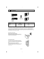
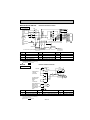
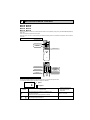
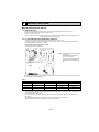
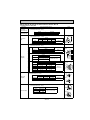
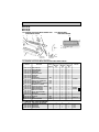
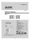
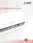
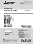
SPLIT-TYPE AIR CONDITIONERS
No. OB274
SERVICE MANUAL
Wireless type
Models
MS09TW
MS12TN
MS15TN
MS17TN
(W)
(W)
(W)
(W)
·
·
·
·
MU09TW
MU12TN
MU15TN
MU17TN
CONTENTS
MS12TN
MS15TN
MS17TN
INDOOR UNIT
1. FEATURES ············································OB274-2
2. TECHNICAL CHANGES ························OB274-3
3. PART NAMES AND FUNCTIONS ········OB274-4
4. SPECIFICATIONS··································OB274-7
5. DATA ····················································OB274-10
6. OUTLINES AND DIMENSIONS ··········OB274-16
7. WIRING DIAGRAM ······························OB274-18
8. REFRIGERANT SYSTEM DIAGRAM··OB274-21
9. MICROPROCESSOR CONTROL ········OB274-23
10. SERVICE FUNCTIONS ························OB274-31
11. TROUBLESHOOTING ··························OB274-33
12. DISASSEMBLY INSTRUCTIONS ········OB274-42
13. PARTS LIST ········································OB274-51
14. OPTIONAL PARTS ······························OB274-57
Remote
controller
MU15TN
MU17TN
OUTDOOR UNIT
The Slim Line.
From Mitsubishi Electric.
TM
C
L IS E D
T
R
L IS E D
T
R
1
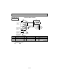
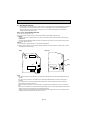
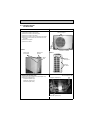
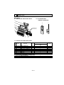
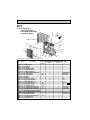
FEATURES
MU09TW
MU12TN
MS09TW
LCD wireless
remote controller
MS12TN MS15TN MS17TN
Models
MU15TN MU17TN
Cooling capacity
SEER
MS09TW
8,500Btu/h
10.2
MS12TN
12,300/12,600Btu/h
11.3/11.3
MS15TN
14,300/14,600Btu/h
10.5/10.5
MS17TN
15,900/16,100Btu/h
10.2/10.2
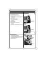
“I FEEL CONTROL” IN OUR LCD WIRELESS REMOTE CONTROLLER WITH ON/OFF PROGRAM TIMER
Mitsubishi Electric’s new wireless remote controller incorporates a number of advanced features that provide even greater control and ease-to-use. It has a liquid crystal display which indicates such information as mode, fan speed and temperature
selected as well as the programmed ON/OFF timer. It is also equipped with “I Feel Control”, a unique Mitsubishi Electric feature that allows the user to adjust the temperature to exactly the level he or she wants simply by tapping the button that
describes present conditions : “Too Cool” or “Too Warm”. The optimum temperature set this way is then memorized for immediate recall whenever the air conditioner is used again.
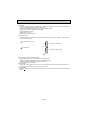
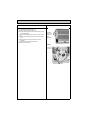
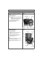
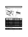
Select desired air flow direction.
REMOTE-CONTROL OPERATION MODE
Using the remote controller, you can select from five airflow settings to match room layout and the location of people. Also, you
can set the vane to swing automatically.
SWING
AUTO-RESTART FUNCTION
The auto restart function restarts the equipment automatically
when power is restored following an outage. Operation resumes in
the mode in which the equipment was running just before the outage.
HIGH PERFORMANCE ROTARY COMPRESSOR
The advanced design of Mitsubishi Electric’s powerful and energy
efficient rotary compressor results in lower operating costs and
longer service life.
OB274-2
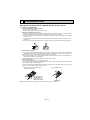
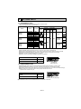
2
TECHNICAL CHANGES
MS09NW2 ➔ MS09TW
1. Indoor unit has changed
2. Remote controller has changed.
MS12NN2 ➔ MS12TN
1. Remote controller has changed.
2. Union size of connect pipe for gas has changed.
MS15NN2 ➔ MS15TN
MS17NN2 ➔ MS17TN
1. Remote controller has changed.
MU09NW2 ➔ MU09TW
1. Outdoor unit has changed.
MU12NN2 ➔ MU12TN
1. Outdoor unit has changed.
MU15NN2 ➔ MU15TN
MU17NN2 ➔ MU17TN
1. Only model name has changed.
OB274-3
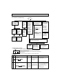
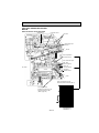
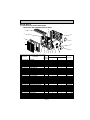
3
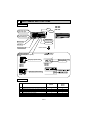
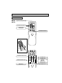
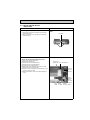
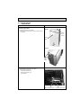
PART NAMES AND FUNCTIONS
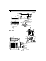
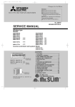
INDOOR UNIT
MS09TW
MS12TN
MS15TN
MS17TN
Grille
Deodorizing filter(option)
(gray sponge type)
Air inlet
Air cleaning filter(option)
(white bellows type)
Remote control
receiving section
Front panel
Horizontal vane
Air filter
Vertical vanes
Remote controller
Operation section
(When the front panel is opened)
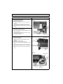
MS09TW
MS09TW
Operation indicator lamp
Emergency operation switch
Receiving section
MS12TN
MS15TN
MS17TN
MS12TN
MS15TN
MS17TN
Emergency operation switch
ACCESSORIES
MS09TW
1
2
3
4
5
6
7
Installation plate
Installation plate fixing screw 4 x 25 mm(0.16 x 0.98 in.)
Remote controller mounting hardware
Fixing screw for 3 3.5 x 16 mm(0.14 x 0.63 in.) (Black)
Battery (AAA) for remote controller
Wireless remote controller Felt tape (Used for left or left-rear piping)
OB274-4
1
5
1
2
2
1
1
MS12TN
MS15TN
MS17TN
1
6
1
2
2
1
1
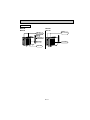
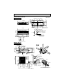
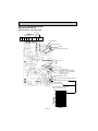
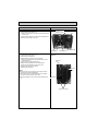
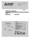
OUTDOOR UNIT
MU09TW
MU12TN
MU15TN
MU17TN
Air inlet (back and side)
Air inlet
(back and side)
Piping
Drain hose
Air outlet
Air outlet
Drain outlet
OB274-5
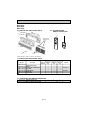
REMOTE CONTROLLER
MS09TW
MS12TN
Signal transmitting section
MS15TN
MS17TN
Operation display section
PM
OPERATE /STOP
(ON /OFF)button
AM
TOO ON/OFF WARM
TOO COOL
TEMPERATURE buttons
Open the front lid.
CLOCK
PM
AM
TOO ON/OFF WARM
FAN SPEED CONTROL button
TOO COOL
FAN
STOP
VANE
START
I FEEL COOL
FAN
OFF-TIMER button
DRY
ON-TIMER button
MODE
HR.
OPERATION SELECT button
MIN.
HR. button
MIN. button
(TIME SET button)
RESET CLOCK
CLOCK SET button
RESET button
VANE CONTROL button
OB274-6
4
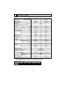
SPECIFICATIONS
Model
Item
❈1
Cooling capacity
Btu/h
Power consumption ❈1
W
EER ❈1 [SEER]❈2
INDOOR UNIT MODEL
External finish
Power supply
V, phase, Hz Max. fuse size (time delay)/
Disconnect switch A
Min. ampacity
A
Fan motor
F.L.A
FAN
Dry
CFM
Airflow Low—Med.—High
COOL Dry(Wet)
CFM
Moisture removal
pt./h
Sound level Low-Med.-High
dB(A)
Cond. drain connection O.D.
in.
W
in.
Dimensions
D
in.
H
in.
Weight
lb.
OUTDOOR UNIT MODEL
External finish
Power supply
V, phase, Hz Max. fuse size (time delay)
A
Min. ampacity
A
Fan motor
F.L.A
Model
Winding resistance (at 68˚F)" Compressor
R.L.A
L.R.A
Refrigerant control
Sound level
dB(A)
W
in.
Dimensions
D
in.
H
in.
Weight
lb.
REMOTE CONTROLLER
Control voltage (by built-in
transformer)
REFRIGERANT PIPING
Pipe size
Liquid
in.
(Min. wall thickness) Gas
in.
Indoor
Connection method
Outdoor
Between the indoor
Height difference
ft.
& outdoor units
Piping length
ft.
Refrigerant charge (R22)
Refrigerant oil (Model)
oz.
MS09TW
MS12TN
8,500
840
10.1 [10.2]
MS09TW
White
115, 1, 60
15
12,300/12,600
1,100/1,130
11.2/11.2 [11.3/11.3]
MS12TN
Cooling
5/8
33-1/2
7-1/2
10-15/16
20
MU09TW
39-15/16
7-1/2
12-5/8
31
MU12TN
Munsell 5Y7/1
115, 1, 60
208/230, 1, 60
0.6
0.43
360-395-452
360(314)-395(342)-452(392)
3.2
36-39-42
15
11
0.60
RH130WGJT
C-R 0.85 C-S 1.21
7.8
41.0
12
0.42
RH167NHDT
C-R 2.16 C-S 3.11
9.0
29.0
Capillary tube
46
30-23/32
10-1/32
21-1/4
71
49
30-3/4
10-1/16
21-1/4
84
Wireless type
12V DC
Not supplied (optional parts) 1/4 (0.0265)
3/8 (0.0285)
1/2 (0.0285)
Flared
Flared
Max. 25
Max. 49
1 Ib. 11 oz.
2 Ib. 9 oz.
9.3 (MS56)
16.1 (MS56)
Operating Range
Maximum
Minimum
0.5
0.37
191-237-289
166(138)-219(184)-272(226)
2.3
26-31-36
Notes : Test conditions are based on ARI 210/240
❈1 : Rating conditions (cooling) — Indoor : 80-FDB, 67-FWB, Outdoor : 95-FDB, (75-FWB)
❈2 : Rating conditions (cooling) — Indoor : 80-FDB, 67-FWB, Outdoor : 82-FDB, 65-FWB
Indoor intake air temperature Outdoor intake air temperature
115-FDB
95-FDB, 71-FWB
67-FDB
67-FDB, 57-FWB
OB274-7
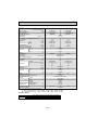
Item
MS15TN
Model
❈1
MS17TN
Cooling capacity
Btu/h
14,300/14,600
15,900/16,100
Power consumption ❈1
W
1,370/1,400
1,570/1,600
EER ❈1 [SEER]❈2
10.4/10.4 (10.5/10.5)
10.1/10.1 (10.2/10.2)
INDOOR UNIT MODEL
MS15TN
MS17TN
External finish
White
Power supply
V, phase, Hz 115, 1, 60
Max. fuse size (time delay)/Disconnect
switch A
15
Min. ampacity
A
0.6
0.7
Fan motor
F.L.A
0.43
0.51
Dry
CFM
360-395-452
406-441-491
Airflow Low—Med.—High
Wet
CFM
293-321-367
346-374-417
Moisture removal
pt./h
4.7
5.1
Sound level Low-Med.-High
dB(A)
36-39-42
40-43-45
Cond. drain connection O.D.
in.
5/8
W
in.
39-15/16
Dimensions
D
in.
7-1/2
H
in.
12-5/8
Weight
lb.
31
OUTDOOR UNIT
MU15TN MU17TN
External finish
Munsell 5Y7/1
Power supply
V, phase, Hz
208/230, 1, 60
Max. fuse size (time delay)
A
20
Min. ampacity
A
14
15
Fan motor
F.L.A
0.52
Model
RH207NHDT
RH231NHDT
Winding resistance (at 68˚F)" C-R 1.68 C-S 2.78
C-R 1.65 C-S 2.67
Compressor
R.L.A
10.0
11.0
L.R.A
35.0
38.0
Refrigerant control
Capillary tube
Sound level
dB(A)
52
52
W
in.
33-7/16
Dimensions
D
in.
11-7/16
H
in.
23-13/16
Weight
lb.
92
97
REMOTE CONTROLLER
Wireless type
Control voltage (by built-in
transformer)
12V DC
REFRIGERANT PIPING
Not supplied (optional parts) Pipe size
Liquid
in.
1/4 (0.0265)
(Min. wall thickness) Gas
in.
5/8 (0.0315)
Indoor
Flared
Connection method
Outdoor
Flared
Between the indoor
Height difference
ft.
Max. 25
& outdoor units
Piping length
ft.
Max. 49
Refrigerant charge (R22)
2 Ib. 14 oz.
3 Ib.
Refrigerant oil (Model)
oz.
16.1 (MS56)
Notes : Test conditions are based on ARI 210/240
❈1 : Rating conditions (cooling) — Indoor : 80-FDB, 67-FWB, Outdoor : 95-FDB, (75-FWB)
❈2 : Rating conditions (cooling) — Indoor : 80-FDB, 67-FWB, Outdoor : 82-FDB, 65-FWB
Operating Range
Cooling
Maximum
Minimum
Indoor intake air temperature Outdoor intake air temperature
115-FDB
95-FDB, 71-FWB
67-FDB
67-FDB, 57-FWB
OB274-8
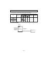
MAX. REFRIGERANT PIPING LENGTH & MAX. HEIGHT DIFFERENCE
Piping size : in.
Length of connecting pipe : in.
Liquid
Gas
Additional piping
Minimum
Max. length : ft.
Outside Wall Outside Minimum
A
diameter thickness diameter Wall thickness
Model
MS09TW
MU09TW
MS12TN
MU12TN
MS15TN
MU15TN
MS17TN
MU17TN
Indoor unit
Outdoor unit
Gas :16-15/16
Gas : 0
[ 3/8
[ 1/2
49
0.0285
[ 5/8
[ 1/4
0.0265
Liquid : 19-11/16
0.0315
MAX. HEIGHT DIFFERENCE
Indoor
unit
w Height difference should be within 25ft regardless of w Max. Height which unit, indoor difference 25ft
or outdoor position is high.
Additional Piping
Max. length
A
Outdoor unit
OB274-9
Liquid : 0
DATA
5
5-1. PERFORMANCE DATA
1) COOLING CAPACITY
MS09TW MS12TN MS15TN MS17TN MU09TW MU12TN MU15TN MU17TN
(115V)
Outdoor intake air DB temperature (˚F)
Indoor air
Model
75
IWB
(˚F)
85
95
105
115
TC
SHC
TPC
TC
SHC
TPC
TC
SHC
TPC
TC
SHC
TPC
TC
SHC
TPC
71
10.4
5.9
0.75
9.7
5.5
0.82
9.1
5.2
0.88
8.5
4.8
0.93
7.8
4.4
0.97
67
9.9
6.9
0.71
9.2
6.4
0.78
8.5
6.0
0.84
7.9
5.5
0.89
7.3
5.1
0.93
63
9.3
7.7
0.67
8.6
7.2
0.74
8.0
6.7
0.80
7.3
6.1
0.86
6.6
5.5
0.89
MS09TW
(208V)
Outdoor intake air DB temperature (˚F)
Indoor air
Model
75
IWB
(˚F)
85
95
105
115
TC
SHC
TPC
TC
SHC
TPC
TC
SHC
TPC
TC
SHC
TPC
TC
SHC
TPC
71
15.1
8.7
0.98
14.1
8.1
1.07
13.2
7.6
1.16
12.3
7.1
1.22
11.3
6.5
1.27
67
14.3
10.1
0.92
13.3
9.4
1.02
12.3
8.7
1.10
11.4
8.1
1.17
10.5
7.5
1.22
63
13.4
11.3
0.88
12.4
10.5
0.97
11.6
9.8
1.05
10.5
8.9
1.12
9.6
8.1
1.17
71
17.5
9.1
1.22
16.4
8.5
1.34
15.4
7.9
1.44
14.3
7.4
1.51
13.2
6.8
1.58
67
16.6
10.8
1.15
15.4
10.0
1.27
14.3
9.3
1.37
13.3
8.6
1.45
12.2
7.9
1.52
63
15.6
12.2
1.10
14.4
11.3
1.21
13.4
10.5
1.31
12.2
9.6
1.40
11.2
8.7
1.45
71
19.5
10.1
1.40
18.2
9.4
1.53
17.1
8.8
1.65
15.9
8.2
1.73
14.6
7.6
1.81
67
18.4
12.0
1.32
17.2
11.2
1.45
15.9
10.3
1.57
14.8
9.6
1.66
13.6
8.8
1.74
63
17.3
13.6
1.26
16.1
12.6
1.39
14.9
11.7
1.50
13.6
10.6
1.60
12.4
9.7
1.66
MS12TN
MS15TN
MS17TN
(230V)
Outdoor intake air DB temperature (˚F)
Indoor air
Model
75
IWB
(˚F)
85
95
105
115
TC
SHC
TPC
TC
SHC
TPC
TC
SHC
TPC
TC
SHC
TPC
TC
SHC
TPC
71
15.4
8.9
1.01
14.4
8.3
1.10
13.5
7.8
1.19
12.6
7.3
1.25
11.6
6.7
1.30
67
14.6
10.4
0.95
13.6
9.7
1.05
12.6
8.9
1.13
11.7
8.3
1.20
10.8
7.6
1.25
63
13.7
11.6
0.90
12.7
10.7
1.00
11.8
10.0
1.08
10.8
9.1
1.15
9.8
8.3
1.20
71
17.9
9.2
1.25
16.7
8.6
1.37
15.7
8.1
1.47
14.6
7.5
1.55
13.4
6.9
1.61
67
16.9
11.0
1.18
15.8
10.2
1.30
14.6
9.5
1.40
13.6
8.8
1.48
12.5
8.1
1.55
63
15.9
12.5
1.12
14.7
11.6
1.24
13.7
10.8
1.34
12.5
9.8
1.43
11.4
8.9
1.48
71
19.7
10.2
1.42
18.4
9.5
1.56
17.3
8.9
1.68
16.1
8.3
1.77
14.8
7.7
1.84
67
18.7
12.1
1.34
17.4
11.3
1.48
16.1
10.5
1.60
15.0
9.7
1.70
13.8
8.9
1.78
63
17.5
13.7 1.28
16.3
12.7
1.42
Notes 1. I WB : Intake air wet-bulb
temperature.
TC : Total Capacity (x103 Btu/h), SHC : Sensible Heat Capacity (x103 Btu/h)
TPC : Total Power Consumption
(kW)
2. SHC is based on 80˚Fof indoor intake air DB temperature.
15.1
11.9
1.53
13.8
10.8
1.63
12.6
9.8
1.70
MS12TN
MS15TN
MS17TN
2) COOLING CAPACITY CORRECTIONS
Refrigerant piping length (one way)
Model
MS09TW
MS12TN
MS15TN
MS17TN
25ft (std)
40ft
1.0
0.954
0.927
49ft
OB274-10
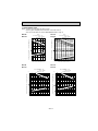
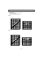
5-2. PERFORMANCE CURVE
NOTE : A point on the curve shows the reference point.
Curves in graph of MS(MU)12/15/17TN shows curves under 230V AC.
As for curves under 208V AC, refer to PERFORMANCE DATA on page 10.
MS09TW
MU09TW
MS12TN
MU12TN
Cooling
SHF at rating condition = 0.70
Airflow = 226CFM
Bypass Factor = 0.26
16
take
air W
B te
mpe
ratu
Total capacity ( o10 Btu/h)
or in
10
re (-
F)
8
71
67
63
6
1.2
erature
1.0
0.8
Indo
or in
Indo
take
Indoor in
temp
air WB
(-F) 71
67
63
0.6
air W
B te
mpe
ratu
re (-
F)
12
71
67
10
63
8
2
take
Indoor in
mperature
air WB te
(-F)
71
67
63
1
65
75
85
95
105
115
Outdoor intake air DB temperature (-F)
67
MS15TN
MU15TN
take
14
Total power consumption (kW)
Total power consumption (kW)
Total capacity ( o10 Btu/h)
12
Cooling
SHF at rating condition = 0.71
Airflow = 392CFM
Bypass Factor = 0.17
75
85
95
105
Outdoor intake air DB temperature (-F)
115
MS17TN
MU17TN
20
take
air W
B te
16
mpe
ratu
re (
14
-F)
71
67
12
63
2
Indoor
intake
air WB
)
ture (-F
tempera
71
67
63
1
67
Cooling
SHF at rating condition = 0.65
Airflow = 417CFM
Bypass Factor = 0.22
Ind
oor
or in
75
85
95
105
Outdoor intake air DB temperature (-F)
Total capacity ( o10 Btu/h)
Indo
Total power consumption (kW)
Total power consumption (kW)
Total capacity ( o10 Btu/h)
18
Cooling
SHF at rating condition = 0.65
Airflow = 367CFM
Bypass Factor = 0.22
115
OB274-11
inta
ke
18
air
WB
tem
per
atu
16
re (
-F)
71
14
67
63
2
e air
r intak
F)
ture (-
mpera
WB te
Indoo
71
67
63
1
67
75
85
95
105
Outdoor intake air DB temperature (-F)
115
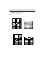
5-3. Condensing pressure
Data is based on the condition of indoor humidity 50%.
Air flow should be set at High.
A point on the curve shows the reference point.
MU09TW
(PSIG)
300
86
80
75
70
280
(PSIG)
100
e
tur
90
ra
e
mp
240
B
rD
te
Suction pressure
Condensing pressure
260
o
do
In
220
200
180
160
68 70
mperature
Indoor DB te
80
86
80
70
75
70
60
50
75
80
85
90
95
40
68 70
100 104( F)
75
80
85
90
95
100
104( F)
Outdoor ambient temperature
Outdoor ambient temperature
MU12TN
(PSIG)
300
86
80
75
70
(PSIG)
110
260
re
100
atu
r
oo
DB
tem
Ind
220
200
180
160
68 70
mperature
Indoor DB te
r
pe
240
Suction pressure
Condensing pressure
280
86
90
80
75
80
70
70
60
75
80
85
90
95
100
104( F)
50
Outdoor ambient temperature
70
75
80
85
90
95
Outdoor
ambient
temperature
100 104( F)
OB274-12
Data is based on the condition of indoor humidity 50%.
Air flow should be set at High.
A point on the curve shows the reference point.
MU15TN
(PSIG)
320
300
86
80
75
70
(PSIG)
100
e
260
tur
90
ra
e
mp
240
r
oo
DB
mperature
Indoor DB te
te
Suction pressure
Condensing pressure
280
Ind
220
200
80
86
80
75
70
70
60
50
180
160
68 70
75
80
85
90
95
40
68 70
100 104( F)
75
Outdoor ambient temperature
80
85
90
95
100 104( F)
Outdoor ambient temperature
MU17TN
(PSIG)
320
300
86
80
75
70
(PSIG)
100
e
260
tur
90
ra
e
mp
B
rD
240
oo
Ind
220
200
86
80
80
75
70
70
60
50
180
160
68 70
mperature
Indoor DB te
te
Suction pressure
Condensing pressure
280
75
80
85
90
95
100 104( F)
Outdoor ambient temperature
40
68 70
75
80
85
90
95
Outdoor ambient temperature
OB274-13
100 104( F)
5-4. STANDARD OPERATION DATA
Model
MS09TW
MS12TN
MS15TN
MS17TN
Unit
Cooling
Cooling
Cooling
Cooling
Btu / h
8,500
12,300/12,600
14,300/14,600
15,900/16,100
SHF
—
0.70
0.71
0.65
0.65
Input
Item
Capacity
Total
kW
0.84
1.10/1.13
1.37/1.40
1.57/1.60
INDOOR UNIT MODEL
MS09TW
MS12TN
MS15TN
MS17TN
Power supply (V, phase, Hz)
115, 1, 60
115, 1, 60
115, 1, 60
115, 1, 60
kW
0.035
0.047
0.047
0.054
A
0.34
0.41
0.41
0.47
MU09TW
MU12TN
MU15TN
MU17TN
Input
Fan motor current
Electrical
circuit
OUTDOOR UNIT MODEL
115, 1, 60
208/230, 1, 60
208/230, 1, 60
208/230, 1, 60
kW
0.805
1.053/1.083
1.323/1.353
1.516/1.546
Comp. current
A
6.61
4.84/4.41
6.01/5.51
7.01/6.41
Fan motor current
A
0.59
0.36/0.39
0.49
0.49
Condensing pressure
PSIG
245
247
256
252
Suction pressure
PSIG
73
85
77
77
˚F
182
175
166
174
Refrigerant Condensing temperature
circuit
Suction temperature
˚F
115
116
116
114
˚F
52
54
48
46
Comp. shell bottom temp
˚F
167
160
154
160
Power supply (V, phase, Hz)
Input
Discharge temperature
Ref. pipe length
ft.
25
25
25
25
Refrigerant charge (R22)
—
1 Ib. 11 oz.
2 Ib. 9 oz.
2 Ib. 14 oz.
3 Ib.
DB
˚F
80
80
80
80
WB
˚F
67
67
67
67
DB
˚F
60
58
55
56
WB
˚F
57
56
54
54
Intake air temperature
Indoor
unit
Discharge air temperature
Fan speed (High)
rpm
890
1,200
1,200
1,290
Airflow (High)
CFM
262(Wet)
392(Wet)
367(Wet)
417(Wet)
DB
˚F
95
95
95
95
WB
˚F
—
—
—
—
Fan speed
rpm
640
700/740
830/900
830/900
Airflow
CFM
985
974/1,034
1,324/1,430
1,288/1,394
Intake air temperature
Outdoor
unit
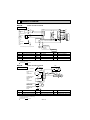
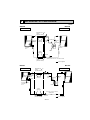
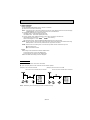
POWER SUPPLY
MS09TW
INDOOR UNIT
115V 60Hz 1[,
2wires
MS12/15/17TN
MS09TW
INDOOR UNIT
SIGNAL WIRE
2 wires 12V DC
115V 60Hz 1[, 2wires
DISCONNECT SWITCH
INDOOR UNIT
115V 60Hz 1[, 2wires
SIGNAL WIRE
2 wires 12V DC
115V 60Hz 1[,
2 wires
MS12/15/17TN
INDOOR UNIT
DISCONNECT SWITCH
SIGNAL WIRE
2 wires 12V DC
115V 60Hz 1[,
2 wires
SIGNAL WIRE
2 wires 12V DC
115V
OUTDOOR UNIT
• Both wirings can be applied to all MODELS.
208/230V 60Hz 1[, 3 wires
115V 60Hz 1[, 2 wires
115V 60Hz 1[, 2 wires
OUTDOOR UNIT
OUTDOOR UNIT
208/230V 60Hz 1[, 3wires
OUTDOOR UNIT
• Outline of MU12TN is as same as one of MU09TW.
✻ Control voltage
Power supply voltage to serial signal circuit is 12V DC. Voltage between 1 + and 2 -- on in-out terminal block will be 12V DC peak.
OB274-14
5-5. OPERATING RANGE
(1) POWER SUPPLY
Indoor unit
Model
Rating
MS09TW
MS12TN
MS15TN
MS17TN
115V Max. 127V
Min. 103V
115V 60Hz 1[
MU09TW
Guaranteed Voltage
MU12TN
MU15TN
MU17TN
Outdoor unit
Min. 198V 208V 230V Max. 253V
208/230V 60Hz 1[
(2) OPERATION
Intake air
temperature
Indoor
Outdoor
DB (-F)
WB (-F)
DB (-F)
WB (-F)
Standard temperature
80
67
95
–
Maximum temperature
95
71
115
–
Minimum temperature
67
57
67
–
Function
Condition
Cooling
–
78%
Maximum humidity
5-6. OUTLET AIR SPEED AND COVERAGE RANGE
Mode
Model
FAN
MS09TW
COOL
FAN
COOL
FAN
COOL
FAN
COOL
MS12TN
MS15TN
MS17TN
Function Air flow Air speedCoverage
(CFM) (ft./sec.) range (ft.)
Dry
21.8
15.4
289
Dry
20.5
14.5
272
Wet
17.1
12.0
226
Dry
29.2
18.2
452
Wet
25.5
15.8
392
Dry
29.2
18.2
452
Wet
23.9
14.8
367
Dry
31.7
19.7
491
Wet
27.0
16.8
417
● The air coverage range is the figure up to the
position where the air speed is 1 ft./sec.,
when air is blown out horizontally from the
unit properly at the High speed position.
The coverage range should be used only as
a general guideline since it varies according
to the size of the room and furniture arranged
in the room.
5-7. ADDITIONAL REFRIGERANT CHARGE (R22(oz.))
Model
MS09TW
MS12TN
MS15TN MS17TN
MU09TW
MU12TN
MU15TN MU17TN
Outdoor unit
precharged
(up to 25ft.)
1 Ib. 11 oz.
2 Ib. 9 oz.
2 Ib. 14 oz.
3 Ib.
Refrigerant
piping
length
(one way)
25ft.
30ft.
35ft.
40ft.
45ft.
49ft.
0
0.53
(1/2)
1.06
(1)
1.59
(3/2)
2.12
(2)
2.54
(5/2)
CALCULATION : Xoz. = 0.53/ 5oz./ft. x (Additional Piping Length-25) ft.
OB274-15
6
OUTLINES AND DIMENSIONS
3-5/16
6-5/8
3/16
MS09TW
9-1/8
10-11/16
Installation plate
INDOOR UNIT
Indoor unit
Unit : inch
3-1/4
12-13/16
33-1/2
{
3-15/16
6-1/2
3/4
Liquid line [1/4 19-11/16
Gas line [3/8 16-15/16
Insulation [1-7/16 O.D
[13/16 I.D
Drain hose [5/8
(Connected part O.D)
Insulation [1-1/8
2-5/8
Air out
4-5/8
Wall hole [2-9/16
3/16
Installation plate
1/4 or more
10-15/16
24-3/4
2-5/16
12-13/16
7-7/16
Air in
2-1/4
1-5/8
1/8
1-5/8
32-3/16
3-1/16
4 in. or more
6-3/8
REQUIRED SPACE
Wireless remote controller
MU09TW MU12TN
4 in
Outdoor
unit
. or
OUTDOOR UNIT
re
mo
mor
e
. or
n
16 i
e
mor
14
Air in
Service panel
Lock nut
in.
or
mo
re
10-1/32
11-7/32
12-19/32
4-9/32
1-1/4
12-19/32
Air in
Drainage 3holes [1-5/16
5-25/32 4-11/32
Airout
Connector
31/32
Grounding terminal
21-1/4
10-1/4
Service panel
13/32
.or
4 in
Liquid refrigerant pipe joint
Refrigerant pipe
(flared) [1/4
6-3/32
3-17/32
43- 35-
1-9/16
4-13/16
19-22/32
30-23/32
2-29/32
4-3/32
OB274-16
Gas refrigerant pipe joint
Refrigerant pipe
(flared) [3/8 (MU09TW)
[1/2 (MU12TN)
Conduit
cover
NOTE: Do not wire 12V DC and 115V AC in same conduit hole.
MS12TN MS15TN MS17TN
17-1/4
1/8
17-11/16
17-11/16
13-7/8
Wall hole [2-15/16
Installation plate
39-15/16
12-5/8
7-1/2
3/16
Installation plate
{
Air in
1-15/16
30-1/2
2-5/16
7-1/2
13/16
8-9/16
10
25-1/2
10-13/16
5-7/8
2-3/8
1-9/16
39-3/16
Unit : inch
Indoor unit
11-11/16
4holes 7/16 O 13/16
INDOOR UNIT
Liquid line [ 5/16 19-11/16
Gas line [1/2 16-15/16
Insulation [ 1-15/16 O.D
[ 1-1/8 I.D
Drain hose [ 5/8
Insulation [ 1-1/8
Air out
6-3/8
3/4
Wireless remote controller
13-31/32
13-3/4
Air in
13/16
4 in.
Drainage hole [5/8
Drainage 3holes [1-5/16
Air out
.
4 in
13-9/16
Air in
12-3/16
11-7/16
3-17/32
4 in.
20
1-15/16
1-3/16
in.
14 i
n.
Service panel
Liquid refrigerant pipe joint
23-13/16
7-3/16
3-15/16
6-3/16
19-11/16
33-7/16
2-15/16
OB274-17
6-5/16
Lock nut
35
11-1/2
30
Refrigerant pipe
(flared) [1/4
13/16
9-3/4
1-3/8
MU15TN MU17TN
OUTDOOR UNIT
Gas refrigerant
pipe joint
Rfrigerant pipe (flared) [5/8
Connector
Conduit
cover
NOTE: Do not wire12V DC and 115V AC in same conduit hole.
7
WIRING DIAGRAM
MS09TW
INDOOR UNIT
(
TO OUTDOOR
UNIT
CONNECTING
WIRES
12V DC
FROM OUTDOOR
UNIT
CONNECTING
WIRES
POWER
SUPPLY
115V
1 phase
60Hz
MODEL WIRING DIAGRAM
TB
2-
W
1+
VLT
N
BLK
L1
CN202
YLW
1
2
HIC1
CN201
NR11
1
2
3
RED
)
TRANS
F11
TAB12
CN
151
TO OUTDOOR
UNIT
CONNECTING
WIRE
RT12
CN
111
RT11
CN
121
BLK
GRY
YLW
BRN
WHT
RED
3
C11 1
2
3
1
2
3
MF
4
5
6
CN211
LD101T ELECTRONIC CONTROL P.C. BOARD
5
5
POWER MONITOR,
MV
W A disconnect may be required by local code.
SR141
CN
112
RECEIVER
P.C.BOARD
REMOTE
CONTROLLER
C11
F11
HIC1
MF
SYMBOL
NAME
SYMBOL
INDOOR FAN CAPACITOR
MV
SYMBOL
NAME
SR141
VANE MOTOR
TB
FUSE (3A)
NR11
VARISTOR
DC / DC CONVERTER
RT11
ROOM TEMPERATURE THERMISTOR
INDOOR FAN MOTOR (INNER FUSE)
RT12
INDOOR COIL THERMISTOR
NAME
SOLID STATE RELAY
TERMINAL BLOCK
NOTE:1. About the outdoor side electric wiring, refer to the outdoor unit electric wiring diagram for servicing.
2. Use copper conductors only.(For field wiring)
3. Symbols below indicate;
: Terminal block,
: Connector
MODEL WIRING DIAGRAM
OUTDOOR UNIT
WHT
TB1
GRN/YLW
C1
GROUND
N
POWER SUPPLY
115V
1phase 60Hz
TO INDOOR UNIT
CONNECTING
WIRES
115V
1 Phase 60Hz
FROM INDOOR UNIT
CONNECTING
WIRES 12V DC
RED MC
R
S
BLK
BLK
WHT
L1
RED
TB2
L1
NO
52C
COM
C
C2
RED
BLK
WHT
1 2 3
MU09TW
SG79J021H01
RED
BLK MF
WHT
RED
N
BLK
1 + VLT
2 – YLW 52C
FROM INDOOR UNIT
CONNECTING
WIRE
SYMBOL
NAME
SYMBOL
C1
COMPRESSOR CAPACITOR
MC
COMPRESSOR (INNER PROTECTOR) TB1,TB2 TERMINAL BLOCK
NAME
C2
OUTDOOR FAN CAPACITOR
MF
OUTDOOR FAN MOTOR (INNER PROTECTOR)
NOTE:1. About the indoor side electric wiring, refer to the indoor unit electric wiring diagram for servicing.
2. Use copper conductors only.(For field wiring)
3. Symbols below indicate;
: Terminal block,
: Connector
OB274-18
SYMBOL
52C
NAME
COMPRESSOR CONTACTOR
VG79B009H01
MS12TN MS15TN MS17TN
2-
TO OUTDOOR
UNIT
CONNECTING
WIRES
12V DC
1+
W
FROM OUTDOOR
UNIT
CONNECTING
WIRES
POWER
SUPPLY
115V
1 phase
60Hz
(
TB
YLW
)
CN
112
CN201
3
2
1
VLT
N
BLK
L1
RED
TAB12 F11
2 1
CN202
CN
102
DSAR
TO OUTDOOR
UNIT
CONNECTING
WIRE
CN
151
3
CN
104
5
CN
101
C11
NAME
DSAR
MF
GRN/YLW
AUTO RESTART
ASSY
RECEIVER
P.C.BOARD
REMOTE
CONTROLLER
SYMBOL
NAME
SYMBOL
NAME
MF
INDOOR FAN MOTOR (INNER FUSE)
RT12
INDOOR COIL THERMISTOR
MV
VANE MOTOR
INDOOR FAN CAPACITOR
SURGE ABSORBER
SR142~SR144 SOLID STATE RELAY
TB
F11
FUSE (3A)
NR11
VARISTOR
HIC1
DC / DC CONVERTER
RT11
ROOM TEMPERATURE THERMISTOR
TERMINAL BLOCK
NOTE:1. About the outdoor side electric wiring, refer to the outdoor unit electric wiring diagram for servicing.
2. Use copper conductors only.(For field wiring)
3. Symbols below indicate;
: Terminal block,
: Connector
MU12TN
OUTDOOR UNIT
WHT
ORN
RED
BLK
YLW
BLU
BRN
3
GRN/YLW
SYMBOL
1
2
3
4
5
6
7
8
ELECTRONIC CONTROL P.C. BOARD
5
DISPLAY
MV
P.C.BOARD
W A disconnect may be required by local code.
RT11
WHT
ORN
RED
BLK
YLW
BLU
LDCOM
LDC11
C11
LDC12
LDFH
SR144
LDFL
SR142
LDFM
SR143
TRANS
BRN
RT12
CN
111
HIC1
NR11
INDOOR UNIT
MODELS WIRING DIAGRAM
VG79B015H01
MODEL WIRING DIAGRAM
TB1
GRN/YLW
POWER SUPPLY
208/230V
1phase 60Hz
L2
N
BLK
L1
RED
C
C1 RED MC
R
S
BLK
BLU
WHT
TB2
L1
TO INDOOR UNIT
CONNECTING
WIRES
115V
1 Phase 60Hz
WHT
NO COM
52C
C2
RED
BLU
WHT
1 2 3
GROUND
RED
BLK
MF
WHT
RED
N
FROM INDOOR UNIT
CONNECTING
WIRES 12V DC
1 + VLT
2 _ YLW 52C
FROM INDOOR UNIT
CONNECTING
WIRE
SYMBOL
NAME
SYMBOL
NAME
C1
COMPRESSOR CAPACITOR
MC
COMPRESSOR(INNER PROTECTOR)
C2
OUTDOOR FAN CAPACITOR
MF
OUTDOOR FAN MOTOR(INNER PROTECTOR)
NOTE:1. About the indoor side electric wiring, refer to the indoor unit electric wiring diagram for servicing.
2. Use copper conductors only.(For field wiring)
3. Symbols below indicate;
: Terminal block,
: Connector
OB274-19
SYMBOL
TB1,TB2
52C
NAME
TERMINAL BLOCK
COMPRESSOR CONTACTOR
VG79B010H01
MU15TN MU17TN
MODELS WIRING DIAGRAM
OUTDOOR UNIT
TB1
WHT
GRN/YLW
GROUND
L2
C
C1
BLU
MC
RED
R
S
BLK
N
FROM INDOOR UNIT
CONNECTING
WIRES 12V DC
WHT
COM
NO
52C
TB2
L1
RED
ORN
C2
RED
4
FROM INDOOR UNIT
CONNECTING WIRES
115V
1 Phase 60Hz
RED
BLK
3
BLU
L1
WHT
2
BLK
ORN
1
POWER SUPPLY
208/230V
1phase 60Hz
RED
MF
N
1
+
2
-
VLT
52C
YLW
FROM INDOOR UNIT
CONNECTING WIRE
SYMBOL
NAME
SYMBOL
NAME
SYMBOL
NAME
C1
COMPRESSOR CAPACITOR
MF
OUTDOOR FAN MOTOR (INNER PROTECTOR)
52C
COMPRESSOR CONTACTOR
C2
OUTDOOR FAN CAPACITOR
TB1
TERMINAL BLOCK
MC
COMPRESSOR (INNER PROTECTOR) TB2
TERMINAL BLOCK
NOTES:1. About
the indoor side electric wiring, refer to the indoor unit electric wiring diagram for servicing.
2. Use copper conductors only.(For field wiring)
3. Symbols below indicate;
:Terminal block,
:Connector
OB274-20
SG79B999H01
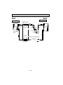
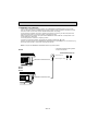
8
REFRIGERANT SYSTEM DIAGRAM
Unit:inch
MU09TW
MS09TW
INDOOR UNIT
OUTDOOR UNIT
Refrigerant pipe
3/8
(option)
(with heat insulator)
Stop valve
with service
port
Indoor heat
exchanger
Indoor coil
thermistor
RT12
Flared
connection
Service
port
Fusible plug
Service
port
Compressor
Room temperature
thermistor
RT11
Outdoor heat
exchanger
Strainer
Muffler
Flared
connection
Stop valve
Refrigerant pipe 1/4
(option)
(with heat insulator)
Capillary tube O.D. 0.12 o I.D. 0.055 o 23-5/8
Flow of refrigerant
MS12TN
MU12TN
INDOOR UNIT
Indoor heat
exchanger
OUTDOOR UNIT
Refrigerant pipe 1/2
(option)
(with heat insulator)
Indoor coil
thermistor
RT12
Distributor
Stop valve
with service port
Flared
connection
Service
port
Room temperature
thermistor
RT11
Fusible plug
Service
port
Muffler
Compressor
Flared
connection
O.D. 0.12 o I.D. 0.071 o 23-5/8
Capillary tube
Refrigerant pipe 1/4 Stop valve
(option)
(with heat insulator)
OB274-21
Strainer
Flow of refrigerant
Outdoor heat
exchanger
MS15TN
MS17TN
MU15TN
MU17TN
OUTDOOR UNIT
INDOOR UNIT
Refrigerant pipe 5/8
(option)
(with heat insulator)
Indoor heat
exchanger
Indoor coil
thermistor
RT12
Distributor
Stop valve
with service port
Flared
connection
Service
port
Fusible plug
Service
port
Accumulator
Room temperature
thermistor
RT11
Muffler
Compressor
Flared
connection
MU15 O.D. 0.12 o I.D. 0.071 o 21-5/8
MU17 O.D. 0.12 o I.D. 0.079 o 27-9/16
Capillary tube
Refrigerant pipe 1/4 Stop valve
(option)
(with heat insulator)
OB274-22
Strainer
Flow of refrigerant
Outdoor heat
exchanger
9
MICROPROCESSOR CONTROL
MS09TW
MS12TN
MS15TN
MS17TN
MU09TW
MU12TN
MU15TN
MU17TN
Once the operation mode are set, the same operation mode can be repeated by simply turning the OPERATE/STOP(ON/OFF)
button ON.
Indoor unit receives the signal with a beep tone.
When the system turns off, 3-minute time delay will operate to protect system from overload and compressor will not restart for
3 minutes.
WIRELESS REMOTE CONTROLLER
Signal transmitting section
Operation display section
PM
AM
OPERATE /STOP
(ON /OFF)button
TOO ON/OFF WARM
TOO COOL
TEMPERATURE buttons
CLOCK
PM
AM
TOO ON/OFF WARM
FAN SPEED CONTROL button
TOO COOL
FAN
STOP
VANE
START
I FEEL COOL
FAN
OFF-TIMER button
DRY
ON-TIMER button
MODE
HR.
HR. button
MIN. button
(TIME SET button)
OPERATION SELECT button
MIN.
RESET CLOCK
CLOCK SET button
RESET button
VANE CONTROL button
INDOOR UNIT DISPLAY SECTION
Operation Indicator lamp
The operation indicator located at the right side of the indoor unit indicates the operation state.
• The following indication applies regardless of shape of the indicatior.
Operation Indicator
lighted
not lighted
Indication
Operation state
Difference between target temperature and room temperature
This shows that the air conditioner is operating to reach the target temperature.
Please wait until the target temperature is obtained.
Approx. 4 ˚F or more
This shows that the room temperature is approaching the target temperature.
Approx. 4 ˚F or less
OB274-23
9-1. “I FEEL CONTROL” OPERATION
Initial room temperature
(1) Press OPERATE/STOP(ON/OFF) button on the remote controller. OPERATION INDICATOR lamp of the indoor unit will
turn on with a beep tone.
(2) Press OPERATION SELECT button to set “I FEEL CONTROL”
Then a beep tone is heard.
(3) The operation mode is determined by the room temperature at
start-up of the operation.
mode
more than 77-F
COOL mode of
“I FEEL CONTROL”
55-F to 77-F
DRY mode of
“I FEEL CONTROL”
● Once the mode is fixed, the mode will not change by room temperature afterwards.
● Under the ON-TIMER operation, the mode is determined according to the room temperature at set time the operation
starts.
● When the system is stopped with the OPERATE/STOP(ON/OFF) button on the remote controller, and restarted within 2
hours in “I FEEL CONTROL” mode, the system operates in previous mode automatically regardless of the room temperature.
Operation time chart
Example
Previous operation
COOL mode of
“I FEEL CONTROL”
or COOL mode
Restart
COOL mode of
“I FEEL CONTROL”
● When the system is restarted after 2 hours or more, the operation mode is determined by the room temperature at startup of the operation.
Operation time chart
Restart
COOL or DRY mode of
“I FEEL CONTROL” that
determined by room
temperature at start-up of
the operation.
Example
Previous operation
COOL mode of
“I FEEL CONTROL”
or COOL mode
(4) The initial set temperature is decided by the initial room temperature.
Mode
COOL mode of
“I FEEL CONTROL”
Initial room temperature
79-F or more
77-F to 79-F
DRY mode of
“I FEEL CONTROL”
55-F to 77-F
Initial set temperature
75-F
Initial room temperature
minus 4-F
Initial room temperature
minus 4-F
w1
w1 When the system is restarted with the remote controller, the system operates with the previous set temperature regardless of the room temperature at restart.
The set temperature is calculated by the previous set temperature.
OB274-24
(5) TEMPERATURE buttons
In “I FEEL CONTROL” mode, set temperature is decided by the microprocessor based on the room temperature.
In addition, set temperature is controlled by TOO WARM or TOO COOL buttons when you feel too cool or too warm.
Each time the TOO WARM or TOO COOL button is pressed, the indoor unit receives the signal and emits a beep tone.
● Fuzzy control
When the TOO COOL or TOO WARM button is pressed, the microprocessor changes the set temperature, considering
the room temperature, the frequency of pressing TOO COOL or TOO WARM button and the user’s preference to heat or
cool. So this is called “Fuzzy control”, and works only in “I FEEL CONTROL” mode.
In DRY mode of “I FEEL CONTROL”, the set temperature doesn’t change.
TOO COOL
… To raise the set temperature 2~4 degrees(˚F)
TOO WARM
… To lower the set temperature 2~4 degrees(˚F)
— COOL mode of “I FEEL CONTROL” —
1. Indoor fan speed control
Indoor fan operates at the set speed by FAN SPEED CONTROL button.
In AUTO the fan speed is as follows.
Fan speed
Initial temperature difference
Room temperature minus set temperature : 4 degrees or more································High
Room temperature minus set temperature : Between 2 and 4 degrees····················Med.
Room temperature minus set temperature : less than 2 degree································Low
Difference between room
temperature and set temperature during operation
4 deg. 7 deg.
2 deg. 3 deg.
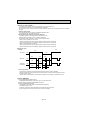
2. Coil frost prevention
① Temperature control
<MS09>
When the indoor coil thermistor RT12 reads 39-F or below for 5 minutes, the coil frost prevention
mode starts.
<MS12/15/17>
When the indoor coil thermistor RT12 reads 30-F or below, the coil frost prevention mode starts
immediately. However the coil frost prevention doesn’t work for 5 minutes since the compressor has
started.
The indoor fan operates at the set speed the compressor stops for 5 minutes.
After that, if RT12 still reads below 39-F (MS09) or below 30-F (MS12/15/17) this mode is prolonged until the
RT12 reads over 39-F (MS09) or 30-F (MS12/15/17).
② Time control
When the three conditions as follows have been satisfied for 1 hour and 45 minutes, compressor stops for 3 minutes.
a. Compressor has been continuously operating.
b. Indoor fan speed is Low or Med..
c. Room temperature is below 79-F.
When compressor stops, the accumulated time is cancelled and when compressor restarts, time counting starts
from the beginning.
Time counting also stops temporarily when the indoor fan speed becomes High or the room temperature exceeds
79˚F. However, when two of the above conditions (b.and c.) are satisfied again. Time accumulation is resumed.
ON
ON
Compressor and
Outdoor fan motor
Indoor fan motor
OFF
ON
OFF
(continuously at set speed)
OB274-25
—DRY mode of “I FEEL CONTROL”—
The system for dry operation uses the same refrigerant circuit as the cooling circuit.
The compressor and the indoor fan are controlled by the temperature.
By such controls, amount of air flow of indoor unit will be reduced in order to lower humidity without much room temperature drop.
1. Indoor fan speed control
Indoor fan operates at the set speed by FAN SPEED CONTROL button.
In AUTO fan operation, fan speed becomes Low.
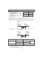
2. The operation of the compressor and indoor/ outdoor fan
Compressor operates by room temperature control and time control.
Set temperature is controlled to fall 4-F as initial set temperature.
Indoor fan and outdoor fan operate in the same cycle as the compressor.
• When the room temperature is 73-F or over:
When the thermostat is ON, the compressor repeats 8 minutes ON and 3 minutes OFF.
When the thermostat is OFF, the compressor repeats 4 minutes OFF and 1 minute ON.
• When the room temperature is under 73-F.
When the thermostat is ON, the compressor repeats 2 minutes ON and 3 minutes OFF.
When the thermostat is OFF, the compressor repeats 4 minutes OFF and 1 minute ON.
Operation time chart
Example
Thermostat
ON
ON
OFF
OFF
Indoor fan
OFF
OFF
ON
Outdoor fan
Compressor
8 min.
OFF
ON
OFF
OFF
ON
ON
ON
ON
OFF
3 min. 4 min.
1 min.
3. Coil frost prevention
• The operation is as same as coil frost prevention during COOL mode of “I FEEL CONTROL”.
• Indoor fan operates at the set speed and the compressor stops for 5 minutes, because protection (Coil frost
prevention) has the priority.
However, when coil frost prevention works while the compressor is not operating, it’s speed becomes Low.
9-2. COOL OPERATION
(1) Press OPERATE/STOP(ON/OFF) button.
OPERATION INDICATOR lamp of the indoor unit turns on with a beep tone.
(2) Select COOL mode with the OPERATION SELECT button.
(3) Press the TEMPERATURE buttons.
(TOO WARM or TOO COOL button) to select the desired temperature.
The setting range is 59 ~ 89-F
✻ Indoor fan continues to operate regardless of thermostat’s OFF-ON at set speed.
✻ Coil frost prevention is as same as COOL mode of “I FEEL CONTROL”.
OB274-26
9-3. DRY OPERATION
F
95
(1) Press OPERATE/STOP(ON/OFF) button.
OPERATION INDICATOR lamp of the indoor unit turns on
with a beep tone.
(2) Select DRY mode with the OPERATION SELECT button.
(3) The microprocessor reads the room temperature and
determines the set temperature. Set temperature is as
shown on the right chart.
Thermostat (SET TEMPERATURE) does not work.
The other operations are same as DRY mode of “I FEEL
CONTROL”.
(4) DRY operation will not function when the room temperature is 55-F or below.
86
77
68
9-4. FAN OPERATION
(1) Press OPERATE/STOP(ON/OFF) button. OPERATION
INDICATOR lamp of the indoor unit turns ON with a
beep tone.
(2) Select FAN mode with the OPERATION SELECT button.
(3) Select the desired fan speed. When AUTO,it becomes
Low.
Only indoor fan operates. Outdoor unit does not operate.
59
50
50
59
68
77
86
95 F
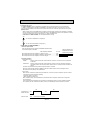
9-5. FAN MOTOR CONTROL<MS09>
(1) Rotational frequency feedback control
The indoor fan motor is equipped with a rotational frequency sensor, and outputs signal to the microprocessor to feedback the rotational frequency. Comparing the current rotational frequency with the target rotational frequency (High,
Med., Low) the microprocessor controls SR141 and adjusts fan motor electric current to make the current rotational frequency close to the target rotational frequency. With this control, when the fan speed is switched, the rotational frequency changes smoothly.
Rotational frequency
High
High
Med.
Low
time
(2) Fan motor lock-up protection
When the rotational frequency feedback signal has not output for 12 seconds, (or when the microprocessor cannot
detect the signal for 12 seconds) the fan motor is regarded locked-up. Then the electric current to the fan motor is shut
off. 3 minutes later, the electric current is applied to the fan motor again. During the fan motor lock-up, the OPERATION
INDICATOR lamp flashes on and off to show the fan motor abnormality. (Refer to page 34.)
9-6. AUTO VANE OPERATION
(1) Vane motor drive
These models are equipped with a stepping motor for the horizontal vane. The rotating direction, speed, and angle of
the motor are controlled by pulse signals (approx. 12V) transmitted from indoor microprocessor.)
(2) The horizontal vane angle and mode changes as follows by pressing the VANE CONTROL button.
AUTO
1
Horizontal
2
3
Middle
OB274-27
4
5
Downward
Swing
(3) Positioning
The vane is once pressed to the vane stopper below to confirm the standard position and then set to the desired angle.
Confirming of standard position is performed in case of follows.
(a) When the OPERATE/STOP(ON/OFF) button is pressed. (POWER ON/OFF)
(b) When the vane control is changed AUTO to MANUAL.
(c) When the SWING is finished.
(d) When the test run starts.
(e) When the power supply turns ON.
(4) VANE AUTO mode
In VANE AUTO mode, the microprocessor automatically determines the vane angle and operation to make the optimum
room-temperature distribution.
1 In COOL and DRY operation
Vane angle is fixed to Angle 1.
2 In FAN operation
Vane angle is fixed to Angle 4.
(5) STOP (operation OFF) and ON-TIMER standby
When the following cases occur, the vane returns to the closed position.
(a) When the OPERATE/STOP (ON/OFF) button is pressed (POWER OFF).
(b) When the operation is stopped by the emergency operation.
(c) When the ON-TIMER is in standby.
(6) Dew prevention
During COOL or DRY operation at vane Angle 4 or 5 when the compressor cumulative operation time exceeds 1 hour,
the vane angle automatically changes to Angle 1 for dew prevention.
(7) SWING MODE
By selecting SWING mode with the VANE CONTROL button, the horizontal vane swings vertically. The remote controller
displays “
”.
OB274-28
9-7. TIMER OPERATION
1. How to set the timer.
(1) Press OPERATE/STOP(ON/OFF) button to start the air conditioner.
(2) Check that the current time is set correctly.
NOTE : Timer operation will not work without setting the current time. Initially “AM0:00” blinks at the current time display
of TIMER MONITOR, so set the current time correctly with CLOCK SET button.
(3) Press ON/OFF TIMER buttons to select the operation.
“ON-TIMER” button... AUTO START operation (ON timer)
“OFF-TIMER” button... AUTO STOP operation (OFF timer)
(4) Press HR. and MIN. button (TIMER SET button) to set the timer. Time setting is 10-minute units.
HR. and MIN. button will work when “
” or “
” mark is flashing.
These marks disappear in 1 minute.
After setting the ON timer, check that OPERATION INDICATOR lamp of the indoor unit lights.
NOTE1 : Be sure to place the remote controller at the position where its signal can reach the air conditioner even during
TIMER operation, or the set time may deviate within the range of about 10 minutes.
NOTE2 : Reset the timer in the following cases, or the set time may deviate and other malfunctions may occur.
● A power failure occurs.
● The circuit breaker functions.
2. Cancel
TIMER setting can be cancelled with the ON/OFF TIMER buttons.
To cancel the ON timer, press the “ON-TIMER” button.
To cancel the OFF timer, press the “OFF-TIMER” button.
TIMER is cancelled and the display of set time disappears.
PROGRAM TIMER
● The OFF timer and ON timer can be used in combination.
● “ ” and “
” display shows the order of the OFF timer and ON timer operation.
(Example 2) The current time is 11:00 AM.
(Example 1) The current time is 8:00 PM.
The unit turns on at 5:00 PM, and off at 9:00 PM.
The unit turns off at 11:00 PM, and on at 6:00 AM.
PM
PM
AM
PM
NOTE : TIMER setting will be cancelled by power failure or breaker functioning.
OB274-29
9-8. EMERGENCY-TEST OPERATION
In case of test run operation or emergency operation, use the EMERGENCY OPERATION switch on the front of the
indoor unit. Emergency operation is available when the remote controller is missing, has failed or the batteries of remote
controller run down. The unit will start and the OPERATION INDICATOR lamp will light.
The first 30 minutes of operation is the test run operation. This operation is for servicing. The indoor fan speed runs at
High speed and the system is in continuous operation. (The thermostat is ON.)
After 30 minutes of test run operation the system shifts to EMERGENCY COOL MODE with a set temperature of 75˚F.
The fan speed shifts to Med. speed.
The coil frost prevention works even in emergency operation.
In the test run or emergency operation, the horizontal vane operates in VANE AUTO (
) mode.
Emergency operation continues until the EMERGENCY OPERATION switch is pressed again or the unit receives any signal from the remote controller. In case of latter normal operation will start.
NOTE : Do not press the EMERGENCY OPERATION switch during normal operation.
• The following indication applies regardless of shape of the indicator.
MS09TW
OPERATION INDICATOR lamp
Press once <Cool>
Press once again <Stop>
EMERGENCY OPERATION switch
MS12TN
MS15TN
MS17TN
EMERGENCY OPERATION switch
OB274-30
10
SERVICE FUNCTIONS
MS09TW MS12TN MS15TN MS17TN
10-1. TIMER SHORT MODE
For service, set time can be shortened by short circuit of JPG and JPS the electronic control P.C. board.
The time will be shortened as follows. (Refer to page 39 or 40.)
Set time : 1 minute ➔ 1-second
Set time : 3 minute ➔ 3-second (It takes 3 minutes for the compressor to start operation. However, the starting time is
shortened by short circuit of JPG and JPS.)
10-2. P.C. BOARD MODIFICATION FOR INDIVIDUAL OPERATION
A maximum of 4 indoor units with wireless remote controllers can be used in a room.
In this case, to operate each indoor unit individually by each remote controller, P.C. boards of remote controller must
be modified according to the indoor unit number.
How to modify the remote controller P.C. board
Remove batteries before modification.
The board has a print as shown below :
NOTE : For remodelling, take out the batteries
and press the
OPERATE/STOP(ON/OFF)button
twice or 3 times at first.
After finish remodelling, put back the
batteries then press the RESET button.
The P.C. board has the print “J1” and “J2”. Solder “J1” and “J2” according to the number of indoor unit as shown in Table 1.
After modification, press the RESET button.
Table 1
1 unit operation
2 units operation
3 units operation
4 units operation
No. 1 unit
No modification
Same as at left
Same as at left
Same as at left
No. 2 unit
–
Solder J1
Same as at left
Same as at left
No. 3 unit
–
–
Solder J2
No. 4 unit
–
–
–
Same as at left
Solder both J1 and J2
How to set the remote controller exclusively for particular indoor unit
After you turn the breaker ON, the first remote controller that sends the signal to the indoor unit will be regarded as the
remote controller for the indoor unit.
The indoor unit will only accepts the signal from the remote controller that has been assigned to the indoor unit once
they are set.
The setting will be cancelled if the breaker has turned off, or the power supply has shut down.
Please conduct the above setting once again after the power has restored.
OB274-31
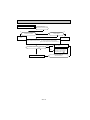
10-3. AUTO RESTART FUNCTION
When the indoor unit is controlled with the remote controller, the operation mode, the set temperature, and the fan speed
are memorized by controlled the indoor electronic control P.C. board(MS09) the auto restart assembly(MS12/1517).
When the main power is turned off and then turned back on, the unit restarts automatically in the memorized set
conditions approximately after 3 minutes.
How to release “AUTO RESTART FUNCTION”
1 Turn off the main power for the unit.
2 Pull out the indoor electronic control P.C. board and the display P.C.board. (Refer to page 42 or 45.)
3 <MS09>
Solder the Jumper wire or the Resistor 220 to the JR07 on the indoor electronic control P.C.board. (Refer to page 39.)
<MS12/15/17>
Disconnect the AUTO RESTART ASSY from CN104, and solder the Jumper wire to JHA on the indoor electronic control
P.C. board. (Refer to page 40.)
Operation
1 If the main power (115V AC) has been cut, the operation settings remain.
2 After the power is restored, the unit restarts automatically according to the memory.(However, it takes at least 3 minutes
for the compressor to start running.)
MS12/15/17
C111
MS09
CN201
C11
CN201
CN211
CN113CN151
CN104
CN112 SW
BZ
SW1
CN102 CN101
IC101
RA102
CN151
IC152
CN112
IC101
CN121
CN111
JHA
JR07
NOTE:
•The operation settings are memorized when 10 seconds have passed after the indoor unit was operated with the remote
controller.
•If the main power is turned off or a power failure occurs while AUTO START/STOP timer is active, the timer setting is
cancelled.
•If the unit has been off with the remote controller before power failure, the auto restart function does not work as the
power button of the remote controller is off.
•To prevent breaker off due to the rush of starting current, systematize other home appliances not to turn on at the same
time.
•When some air conditioners are connected to the same power supply system, if they are operated before power failure, the
starting current of all the compressors may flow simultaneously at restart.
Therefore, the special counter-measures are required to prevent the main voltage-drop or the rush of the starting current
by adding to the system that allows the units to start one by one.
OB274-32
11
TROUBLESHOOTING
MS09TW MS12TN MS15TN MS17TN MU09TW MU12TN MU15TN MU17TN
11-1. Cautions on troubleshooting
1. Before troubleshooting, check the following:
1) Check the power supply voltage.
2) Check the indoor/outdoor connecting wire for mis-wiring.
2. Take care the following during servicing.
1) Before servicing the air conditioner, first be sure to turn off the remote controller to stop the unit, and then after confirming the horizontal vane is closed, turn off the breaker and / or disconnect the power plug.
2) Be sure to turn OFF the power supply before removing the front panel, the cabinet, the top panel, and the electronic
control P.C. board.
3) When removing the electronic control P.C. board, hold the edge of the board with care NOT to apply stress on the
components.
4) When connecting or disconnecting the connectors, hold the housing of the connector. DO NOT pull the lead wires.
Housing point
Lead wiring
3. Troubleshooting procedure
1) First, check if the OPERATION INDICATOR lamp on the indoor unit is flashing on and off to indicate an abnormality.
To make sure, check how many times the abnormality indication is flashing on and off before starting service work.
2) Before servicing check that the connector and terminal are connected properly.
3) If the electronic control P.C. board is supposed to be defective, check the copper foil pattern for disconnection and
the components for bursting and discoloration.
4) When troubleshooting, refer to the flow chart and the check table on page 34.
4. How to replace batteries
Weak batteries may cause the remote controller malfunction.
In this case, the remote controller can be repaired only by the battery replacement. To operate the remote controller normally, replace the batteries in the following order.
This remote controller has the RESET button. After refilling new batteries, press the RESET button with tip end of ball
point pen or the like, and then use the remote controller.
2 Press the RESET button.
1 Remove the front lid and replace batteries.
Then re-attach the front lid.
Insert the negative pole of the batteries first.
Check if the polarity of the batteries are correct.
RESET button
NOTE : If the RESET button is not pressed, the remote controller may not operate correctly.
OB274-33
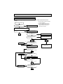
11-2. Instruction of troubleshooting
Indoor unit operates. Outdoor unit
doesn’t operate.
Indoor unit
doesn’t
receive the
signal from
remote
controller.
Outdoor unit
doesn’t operate even in
Test Run
mode.
Outdoor unit
operates in
only Test
Run mode.
Refer to B
”Check of
remote controller and
receiver P.C.
board” on
page 37.
Refer to D
“Check of
outdoor unit”
on page 38.
Check room
temperature
thermistor.
Start
<MS12/15/17>
When the
remote controller
is pressed or
when the
EMERGENCY
OPERATION
switch is
pressed,the
indoor fan does
not rotate with
OPERATION
INDICATOR
lamp on.
OPERATION INDICATOR
lamp on the indoor unit is
flashing on and off.
2-time flash
2.5-second OFF
Indoor unit doesn’t
receive the signal
from remote controller.
Also, operation
indicator lamp
doesn’t flash,
when the emergency operation
switch is pressed.
<MS09>
3-time flash
Refer to C “Check
of indoor electronic control P.C.
board” on page
38.
2.5-second OFF
Cause:Indoor unit
2-time-Room temperature/Indoor coil thermistor trouble.
3-time-Indoor fan motor trouble
Check indoor coil
thermistor. Refer
to“Test point diagram and voltage”
on page 39 or 40.
1. Troubleshooting check table
• The following indication applies regardless of shape of the indicatior.
Refer to A
“Check of indoor
fan motor” on
page 36.
Check room temperature.
Refer to“Test point diagram and voltage” on
page 39 or 40.
flashing
· Flashing of the OPERATION INDICATOR lamp (on the left-hand side) indicates possible abnormalities.
· The OPERATION INDICATOR lamp (on the left-hand side) is lighted during normal operation.
Before taking measures make sure that the symptom reappears, for accurate troubleshooting.
Self check table
Operation Indicator
NO.
Abnormal
point
Indoor coil
thermistor
1
Room
temperature thermistor
Indication
2-time flash
Outdoor unit
does not run.
Detect method
Check point
● Check resistance of thermistor.
Detects Indoor coil/room tem- ● Re-connect connector.
● Check indoor electric P.C. board.
perature thermistor short or
open circuit every 8 seconds
during operation.
2.5-second OFF
<MS09>
3-time flash
2
Symptom
Indoor fan
motor
2.5-second OFF
Indoor fan
repeats 12 seconds ON and 3
minutes OFF.
When the indoor
fan breaks, the
fan keeps stopping.
When rotational frequency
feedback signal is not emit
during 12-second indoor fan
operation.
OB274-34
● Disconnect connector CN211 and then
check connector CN121 2 - 3 to make
sure rotational frequency feedback signal
of 1.5V or over exists.
● Check indoor electronic control P.C.
board.
● Check indoor fan motor.
● Re-connect connector.
MS09TW MS12TN MS15TN MS17TN MU09TW MU12TN MU15TN MU17TN
2. Trouble criterion of main parts
Figure
Check method and criterion
Part name
Room
temperature
thermistor(RT11)
Indoor coil
thermistor(RT12)
Measure the resistance with a tester.
(Part temperature 50°F ~ 86°F)
Normal
8k" ~ 20k"
Abnormal
Open or short-circuit
Measure the resistance between the terminals with a tester.
(Part temperature 14°F ~ 104°F)
Compressor
(MC)
C-R
C-S
MU09
0.7~1.0"
1.0~1.4"
Normal
MU15
MU12
1.9~2.4" 1.4~1.9"
2.7~3.4" 2.4~3.0"
MU17
1.4~1.8"
2.3~2.9"
WHT
P
Abnormal
Open or
short-circuit
RED
BLK
Motor part
Measure the resistance between the terminals with a tester.
(Part temperature 50°F ~ 86°F)
Normal
MS09
76~83 "
70~76 "
WHT-BLK
BLK-RED
Abnormal
MS09
Open or
short-circuit
WHT
RED
MAIN
AUX. BLK
FUSE
Sensor part
Measure the voltage Power ON.
Indoor fan
motor(MF)
YLW-GRY
YLW
Normal
MS09
4.5 ~ 5.5V
BRN-YLW
Abnormal
BRN
(When fan revolved one time)
0V➔5V➔0V (Approx.)
Motor part
MS12/15
65~72"
8~10"
4~6"
5~7"
28~31"
MS17
52~57"
10~12"
4~5"
5~6"
35~39"
Abnormal
MU09
WHT-BLK
BLK-RED
54~67"
58~72"
MS12/15/17
BLK
AUX.1
Open or
short-circuit
AUX.2
AUX.3
YLW
MAIN
BLU
BRN
FUSE
AUX.4
RED
Measure the resistance between the terminals with a tester.
(Part temperature14°F ~ 104°F)
Outdoor fan
motor(MF)
1
2
3
GRY
Remain 0V or 5V
Normal
WHT-BLK
BLK-YLW
YLW-BLU
BLU-BRN
BRN-RED
1
2
3
MU09/12
BLK
P
AUX.
MAIN
RED
Normal
MU12
116~143"
215~264"
MU15/17
102~126"
97~120"
Abnormal
WHT
Open or
short-circuit
MU15/17
BLK
P
AUX.
RED
MAIN
ORN
Measure the resistance between the terminals with a tester.
(Part temperature 50°F ~ 86°F)
WHT
ORN
WHT
MS09
RED
ROTOR
Normal
MS09
Vane motor(MV)
Abnormal
MS12/15/17
BRN- other one RED- other one
YLW
BRN
ORN
Open or short-circuit
GRN
MS12/15/17
282 ~ 306" 358 ~ 388"
PNK
ROTOR
ORN
RED
YLW
BLU
P:INNER PROTECTOR
OB274-35
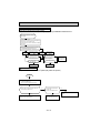
A Check of indoor fan motor
Turn OFF the power supply.
Check connector (Fan motor) visually.
Indoor fan does not operate.
No
Are lead wires connected?
No
Is soldered point of the connector
correctly soldered?
Yes
Yes
Re-connect the lead
wires.
Re-solder it.
Disconnect lead wires from connector (Fan motor).
Measure resistance between lead wires
No.1 and No.3 and then No.2 and No.3 (MS09)
No.1 and No.4 and then No.3 and No.4 (MS12/15/17)
{
MS12/15/17
No
(others)
Is resistance 0 (short circuit) or
}
Replace the indoor electronic control P.C. board.
(open circuit)?
Yes ( 0 or
)
MS09
Repair or replace the indoor fan motor.
No
OB274-36
Insert screwdriver into air outlet and
rotate indoor fan (motor) slowly for
1 revolution or more, and measure
voltage between CN 121 1-2.
Does voltage repeat 0V DC
and more than 5V DC?
Yes
B Check of remote controller and receiver P.C. board
Indoor unit operates by pressing the EMERGENCY OPERATION switch, but does not operate with the remote
controller.
Switch on the remote controller
Is LCD display on remote controller displayed?
No
Replace the batteries.(Refer to page 33.)
(not clear)
wCheck the remote controller is exclusive
for this air conditioner.
wIn case of replacing the receiver P.C.
board of MS09TW, replace the indoor
electronic control P.C. board with it
because they are unified.
Yes
Remove batteries, then set them back and press the RESET
button. Check if the unit operates with the remote controller.
Does the unit operate with remote
controller?
No
Turn a radio to AM and press switch on
remote controller.
Yes
No
OK
Replace the remote controller.
Is noise heard from radio?
Yes
Are there any fluorescent lights of
inverter or rapid-start type within
the range of 3.28ft.?
Yes
● Re-install the unit away from lights.
● Attach a filter on receiving part.
No
MS12/15/17
No
Connect properly.
Is the connector connecting receiver
P.C. board and indoor electronic control P.C. board properly connected?
Yes
Replace the receiver P.C. board.
No
Does the unit receive signal of
ON/OFF with the remote controller
and emit a beep tone?
Yes
OK
Connect properly.
No
Is auto restart assembly properly
connected?
Yes
Replace the auto restart assembly.
No
Does the unit receive signal of
ON/OFF with remote controller
and emit a beep tone?
Yes
OK
Replace the indoor electronic
control P.C. board.
No
MS09
Does the unit receive signal of
ON/OFF with remote controller
and emit a beep tone?
Yes
OK
OB274-37
Replace the power monitor, receiver
P.C. board with the indoor electronic
control P.C. board.
C Check of indoor electronic control P.C. board
The unit doesn’t operate with the remote controller.
Also, the OPERATION INDICATOR lamp doesn’t light up by pressing the EMERGENCY OPERATION switch.
Check the both “parts side” and “pattern side” of indoor electronic control P.C. board visually.
Turn OFF the power supply.
Remove indoor fan motor connector CN211(MS09 only) and vane motor connector CN151 from the indoor electronic control P.C. board and turn ON the power supply.
Does the unit operate with the remote controller or No
the OPERATION INDICATOR lamp light up by pressing the EMERGENCY OPERATION switch?
Yes
Turn OFF the power supply.
Replace the vane motor.
Yes
Is winding resistance of vane motor 0 "?
Turn OFF the power supply.
Yes
No
Is fuse(F11) blown?
No
Replace the indoor electronic control P.C. board.
Be sure to check both fuse and varistor in any case.
Be sure to check both resistances.
Is winding resistance of fan motor 0 "?
Replace the fuse.
No
Is varistor(NR11) burnt?
No
Yes
Yes
Replace the varistor.
Replace the fan motor.
D Check of outdoor unit
Compressor and / or outdoor fan doesn’t operate.(Only indoor fan operates.)
Start
Press EMERGENCY OPERATION switch.
3-minute time delay works.
Test run operation operates for 30 minutes.
Check voltage to terminal block of outdoor unit.
Is there 12V DC between 2-1?
No
Check voltage to terminal block
of indoor unit.
Is there 12V DC between 2-1?
Yes
Check the wiring, compressor contactor (52C),
outdoor fan motor and compressor.
Yes
Re-connect the continuity of
indoor and outdoor unit connection.
OB274-38
No
Replace the indoor electronic control P.C.
board.
TEST POINT DIAGRAM AND VOLTAGE
MS09TW
Indoor electronic control P.C. board
Varistor(NR11)
Fuse 250V AC 3A
Fan motor
Power supply input
115V AC
–
+
}
12V DC
Room temperature
thermistor (RT11)
Timer short mode point
(JPS, JPG)
(Refer to page 31.)
Indoor coil
thermistor (RT12)
Fan motor
Emergency
operation switch
+
–
}
5V DC
Indoor coil thermistor (RT12)
Room temperature thermistor (RT11)
Auto restart function
Solder the Jumper wire or the
Resistor 220" to the JR07.
(Refer to page 32.)
32 50 68 86 104 122 140
F
OB274-39
TEST POINT DIAGRAM AND VOLTAGE
MS12TN MS15TN MS17TN
Indoor electronic control P.C. board
}
Fan motor
8 7 5 6 4
C11
}
Med. Low High
3
2
1
Varistor(NR11)
Fuse 250V AC 3.0A
CN201
}
Power supply input 115V AC
JP7
+
JP9
--
JP11
+
JP24
--
}
12V DC
}
5V DC
Auto restart function
Disconnect the AUTO RESTART
ASSY from CN104, and solder the
JHA
Jumper wire to JHA.
(Refer to page 32.)
Emergency operation switch
CN104
}
}
JPS
Timer short mode point (Refer to page 31.)
JPG
Indoor coil thermistor (RT12)
Room temperature
thermistor (RT11)
Room temperature thermistor (RT11)
Indoor coil thermistor (RT12)
32 50 68 86 104 122 140
F
OB274-40
RELAY OPERATION
MS09TW
MS12TN
MS15TN
MS17TN
1. COMPRESSOR CONTACTOR
• EACH MODE
MODE
COOL & COOL mode
of I FEEL CONTROL
THERMOSTAT
52C CONTACTOR
ON
ON
FAN
AUTO or set speed
OFF
OFF
DRY & DRY mode
of I FEEL CONTROL
INDOOR FAN SPEED
ON
OFF for 2 min. after unit starts
operation
Repeat of 8 min. ON/ 3min. OFF operation
or 2 min. ON/3 min. OFF operation
OFF
Repeat of 4 min. OFF/
1 min. ON operation
OFF
OFF
AUTO or set speed
AUTO or set speed links with
52C CONTACTOR
AUTO or set speed
NOTE : Once the compressor is OFF, “3-minute time delay circuit” works at next start-up.
• COIL FROST PREVENTION
MODE
52C CONTACTOR
THERMOSTAT
INDOOR FAN SPEED
COOL & COOL mode
of I FEEL CONTROL
AUTO or set speed
ON
DRY & DRY mode
of I FEEL CONTROL
OFF for 5 min. After that, OFF is
prolonged until
indoor coil thermistor AUTO or set speed reads termination
temperature.
<MS12/15/17>
Low speed when coil frost prevention starts while COMPRESSOR OFF
2. SOLID STATE RELAY (INDOOR FAN MOTOR RELAY)
MS12TN MS15TN MS17TN
Indoor fan speed
Relay turning ON
High
SR144
Med.
SR143
Low
SR142
OFF
All fan relays are OFF.
OB274-41
12
DISASSEMBLY INSTRUCTIONS
<"Terminal with lock mechanism" Detaching points>
In case of terminal with lock mechanism, detach the terminal as shown below.
There are two types ( Refer to (1) and (2)) of the terminal with lock mechanism.
The terminal with no lock mechanism can be removed by pulling it out.
Check the shape of the terminal and work.
(1) Slide the sleeve and check if there is a locking lever or not.
(2) The terminal with this connector is a terminal with lock mechanism.
Sleeve
Locking lever
1Slide the sleeve.
2Pull the terminal while pushing the locking
lever.
1Hold the sleeve, and pull out the terminal slowly.
Connector
12-1. MS09TW
INDOOR UNIT
OPERATING PROCEDURE
PHOTOS
1. Removing the front panel
(1) Remove the screw caps at the bottom of the front panel.
Remove the screws.
(2) Pull the panel down to your side slightly and unhook the
catches at the top.
Photo 1
Front panel
Screws
2. Removing the electronic control P.C. board and the
power monitor, receiver P.C. board
Photo 2
(1) Remove the front panel. (Refer to 1)
(2) Remove the screw of the electrical cover.
Remove the electrical cover.
(3) Remove the screw of the terminal block.
(4) Disconnect all the connectors and all the lead wires on the
electronic control P.C. board.
(5) Remove the electronic control P.C. board.
(6) Remove the R.L holder.
(7) Open the R.L holder and remove the power monitor,
receiver P.C. board.
Indoor electronic
control P.C. board
Screw of the terminal block
Screw of the
electrical cover
R.L holder
Power monitor,
receiver P.C.
board
OB274-42
OPERATING PROCEDURE
PHOTOS
Photo 3
3. Removing the electrical box
(1) Remove the front panel. (Refer to 1)
(2) Remove the electrical cover. (Refer to 2)
(3) Disconnect the connector of the indoor coil
thermistor (CN112).
(4) Disconnect the motor connector (CN211 and CN121) and
the vane motor connector (CN151) on the electronic
control P.C. board.
(5) Remove the screw of ground wire.
(6) Remove the fan motor lead wire and indoor coil thermistor
lead wire from the electrical box.
(7) Remove the lead wire of vane motor from the bottom of
electrical box.
(8) Remove the R.L holder.
(9) Remove the screw of the conduit cover.
(10) Pull down the conduit cover and remove it.
(11) Remove the screw of the conduit plate and remove the
conduit plate.
(12) Remove the screw fixing the electrical box, remove the
electrical box.
Screw of the ground wire
Conduit cover
Photo 4
Screw fixing the
electrical box
Screws of the
conduit plate
Photo 5
4. Removing the vane motor
(1) Remove the front panel. (Refer to 1)
(2) Remove the electrical box. (Refer to 3)
(3) Pull out the drain hose from the nozzle assembly, remove
the nozzle assembly.
(4) Remove the screws (both upper and lower) of the vane
motor, disconnect the connector.
(5) Remove the vane motor.
Screws of
the vane
motor
Vane motor
OB274-43
OPERATING PROCEDURE
PHOTOS
5. Removing the line flow fan and the indoor fan motor
(1) Remove the front panel. (Refer to 1)
(2) Remove the electrical box. (Refer to 3)
(3) Pull out the drain hose from the nozzle assembly, remove
the nozzle assembly.
(4) Remove the hexagon socket set screw from the line flow
fan.
(5) Remove the screws fixing the fan motor, remove the fan
motor.
(6) Remove the screws fixing the left side of the heat
exchanger.
(7) Lifting the left side of the heat exchanger.
(8) Remove the line flow fan.
Photo 6
Screws fixing the left
side of the
heat
exchanger
Photo 7
Indoor coil
thermistor
Screws of the fan motor
OB274-44
12-2. MS12TN MS15TN MS17TN
INDOOR UNIT
OPERATING PROCEDURE
PHOTOS
1. Removing the front panel
Photo 1
(1) Remove the screw caps at the bottom of the front panel.
Remove the screws.
(2) Pull the panel down to your side slightly and unhook the
catches at the top.
Front panel
Screws
2. Removing the electronic control P.C. board, the
receiver P.C. board and the display P.C. board
(1)
(2)
(3)
(4)
(5)
(6)
(7)
(8)
Remove the front panel. (Refer to 1)
Remove the electrical cover.
Remove the screw of the terminal cover.
Remove the screw of the terminal block.
Unhook the catch of the lamp holder.
Remove the receiver holder and the receiver P.C. board.
Remove the screw of the ground wire.
Disconnect all the connectors and all the lead wires on the
electronic control P.C. board.
(9) Remove the electronic control P.C. board and display P.C.
board.
Photo 2
Screw of the
ground wire Indoor coil thermistor
Screw of
the terminal block
Indoor
electronic
control
P.C. board
Receiver
Lamp Display
Receiver
holder P.C. board P.C. board holder
OB274-45
OPERATING PROCEDURE
PHOTOS
3. Removing the electrical box
(1) Remove the front panel. (Refer to 1)
(2) Remove the electrical cover.
(3) Disconnect the connector of the indoor coil thermistor
(CN112).
(4) Disconnect the motor connector and the vane motor connector (CN151) on the electronic control P.C. board.
(5) Remove the screw of the electrical box, remove the electrical box.
Photo 3
Screws
of the
vane
motor
4. Removing the vane motor
(1) Remove the front panel. (Refer to 1)
(2) Remove the electrical box. (Refer to 3)
(3) Pull out the drain hose from the nozzle assembly, remove
the nozzle assembly.
(4) Remove the screws (both upper and lower) of the vane
motor, disconnect the connector.
(5) Remove the vane motor.
5. Removing the indoor fan motor and the line flow fan
(1) Remove the front panel.
(2) Remove the electrical box.
(3) Unhook the catches on the both sides of the nozzle
assembly.
(4) Remove the nozzle assembly.
(5) Remove the screws of the bearing support.
(6) Remove the screw of the heat exchanger and unhook the
catch.
(7) Lifting the heat exchanger, remove the bearing support.
(8) Loose the screw fixing the line flow fan, remove the line flow
fan.
(9) Remove the screws of the motor band, remove the fan
motor.
Screw of the
electrical cover
Vane motor
Photo 4
Heat exchanger
Catch
Heat exchanger
screw
Screws of the
bearing support
Photo 5
Indoor fan motor
Screws
of the
motor
band
Line flow fan
OB274-46
Screws of the
motor band
12-3. MU09TW MU12TN
OUTDOOR UNIT
OPERATING PROCEDURE
PHOTOS
1. Removing the cabinet
(1)
(2)
(3)
(4)
(5)
Remove the
Remove the
Remove the
Remove the
Remove the
the insides.
(6) Remove the
(7) Remove the
screws of the top panel.
screws of the service panel.
screws of the cabinet.
screws of the front panel and motor support.
service panel, and remove the screw from
Photo 1
Screws of the front panel
and motor support
top panel.
cabinet.
Screws
of the
cabinet
Photo 3
Screws of the
service panel
Screws of the cabinet
Photo 2
Screws of the
top panel
Service
panel
Screws of
the top panel
Screws of
the cabinet
Photo 4
2. Removing the electrical parts
(1) Remove the service panel and the cabinet.(Refer to 1)
(2) Remove the following parts.
•Compressor capacitor (C1)
•Outdoor fan capacitor (C2)
•Terminal block (TB1, TB2)
Terminal block(TB1, TB2)
Compressor capacitor(C1)
Outdoor fan capacitor (C2)
OB274-47
OPERATING PROCEDURE
PHOTOS
3. Removing the propeller fan and the outdoor fan
motor
(1) Remove the cabinet. (Refer to 1)
(2) Remove the propeller fan nut.
(3) Remove the propeller fan.
NOTE : Loose the propeller fan in the rotating direction for
removal.
When attaching the propeller fan, align the mark on the
propeller fan and the motor shaft cut section.
Set the propeller fan in position by using the cut on the
shaft and the mark on the propeller fan.
(4) Remove lead clamps and fan motor lead wires.
(5) Remove screws fixing the fan motor.
(6) Remove the outdoor fan motor.
Photo 5
Screws of the
outdoor fan motor
Propeller fan
4. Removing the compressor
Lead clamps
Hook
Propeller fan nut
Outdoor fan motor
Photo 6
(1)
(2)
(3)
(4)
(5)
Remove the cabinet. (Refer to 1)
Remove the relay panel.
Remove the soundproof felt.
Remove the terminal cover on the compressor.
Disconnect lead wires from the glass terminal of the compressor.
(6) Recover gas from the refrigerant circuit.
(7) Disconnect the welded part of the discharge pipe.
(8) Disconnect the welded part of the suction pipe.
(9) Remove nuts fixing the compressor.
(10) Remove the compressor.
Discharge pipe
Suction pipe
Glass
terminal
Compressor
NOTE
● Before using the torch, reclaim gas from the pipes until the
pressure gauge shows 0 PSI(GAUGE).
● Use the torch under the condition that gas can be released
even when the inner pressure rises by heat.
● Reclaim all refrigerant in an environmentally acceptable manner.
Compressor
set nuts
OB274-48
Terminal cover
12-4. MU15TN MU17TN
OUTDOOR UNIT
OPERATING PROCEDURE
PHOTOS
1. Removing the cabinet
Photo 1
(1) Remove the screws of the cabinet.
(2) Hold the bottom of the cabinet on the both side to remove
the cabinet.
Screws
of the
cabinet
Service
panel
Photo 2
Screws
of the
cabinet
2. Removing the electrical parts
Photo 3
(1) Remove the service panel and the cabinet.
(2) Remove the following parts.
•Compressor capacitor (C1)
•Outdoor fan capacitor (C2)
•Terminal block
Outdoor fan capacitor(C2)
OB274-49
Terminal block(TB)
Compressor capacitor(C1)
OPERATING PROCEDURE
PHOTOS
3. Removing the outdoor fan motor
Photo 4 Screws of the
(1) Remove the cabinet. (Refer to 1)
(2) Disconnect the connector and remove the hooked lead wire
from fan motor.
(3) Remove the propeller fan nut and remove the propeller fan.
(4) Remove screws fixing the fan motor.
outdoor fan motor
Hook
Connector
Soundproof felt
Propeller fan
4. Removing the compressor
(1)
(2)
(3)
(4)
(5)
(6)
(7)
(8)
(9)
Remove the cabinet. (Refer to 1)
Remove the soundproof felt.
Remove the terminal cover on the compressor.
Disconnect lead wires from the glass terminal of the compressor.(Refer to 2)
Recover gas from the refrigerant circuit.
Disconnect the welded part of the discharge pipe.
Disconnect the welded part of the suction pipe.
Remove nuts fixing the compressor.
Remove the compressor.
Propeller fan nut
Photo 5
Discharge
pipe
Suction
pipe
NOTE
● Before using the torch, reclaim gas from the pipes until the
pressure gauge shows 0 PSI(GAUGE).
● Use the torch under the condition that gas can be released
even when the inner pressure rises by heat.
● Reclaim all refrigerant in an environmentally acceptable manner.
Compressor
Compressor set nuts
OB274-50
13
PARTS LIST
MS09TW (W)
13-1. INDOOR UNIT STRUCTURAL PARTS
13-2. ACCESSORY AND
REMOTE CONTROLLER
1
2
10
11
3
4
5
9
Optional parts
(See page 57.)
6
7
8
13-1. INDOOR UNIT STRUCTURAL PARTS
No.
1
2
3
4
5
6
7
8
9
Parts No.
E02
E02
E02
E02
E02
E02
E02
E02
E02
408
409
409
424
409
424
408
408
409
970
234
976
000
067
010
142
100
975
Parts Name
Symbol in Wiring Diagram
INSTALLATION PLATE
BOX(W)
CORNER BOX LEFT (W)
FRONT PANEL ASSEMBLY(W)
SCREW CAP(W)
GRILLE (W)
CATCH (W)
AIR FILTER
CORNER BOX RIGHT (W)
Q'ty / set
MS09TW
(W)
1
1
1
1
2
1
3
2
1
13-2. ACCESSORY AND REMOTE CONTROLLER
10 E02 541 426 REMOTE CONTROLLER 11 E02 527 083 REMOTE CONTROLLER HOLDER
1
1
OB274-51
Remarks
Including 5,6,7
2PCS/SET
3PCS/SET
MS09TW (W)
13-3. INDOOR UNIT ELECTRICAL PARTS AND 13-4. INDOOR UNIT HEAT EXCHANGER
FUNCTIONAL PARTS
1
17
2
16
19
3
15
SLEEVE
BEARING
4
ROOM TEMPERATURE
THERMISTOR
18
5
14
6
12
13
7
FUSE
8
VARISTOR
9
10
11
20
21
13-3. INDOOR UNIT ELECTRICAL PARTS AND FUNCTIONAL PARTS
No.
Parts No.
E02
E02
E02
E02
E02
E02
E02
E02
E02
E02
E02
E02
E02
E02
E02
E02
E02
E02
1
2
3
4
5
6
7
8
9
10
11
12
13
14
15
16
17
18
408
408
001
408
409
409
409
268
268
408
541
408
541
268
541
151
408
408
302
509
504
702
235
040
041
382
385
034
452
303
308
300
375
505
307
333
Parts Name
LINE FLOW FAN
BEARING MOUNT
SLEEVE BEARING
DRAIN HOSE
NOZZLE (W)
VANE UPPER (W)
VANE LOWER (W)
FUSE
VARISTOR
VANE CRANK SET
ELECTRONIC CONTROL P.C.BOARD VANE MOTOR
ROOM TEMPERATURE THERMISTOR
INDOOR FAN MOTOR
TERMINAL BLOCK
FAN MOTOR RUBBER MOUNT
INDOOR COIL THERMISTOR
MOTOR BAND
13-4. INDOOR UNIT HEAT EXCHANGER
Symbol in Wiring Diagram
Remarks
MS09TW
(W)
1
1
1
1
1
1
1
1
1
1
1
1
1
1
1
2
1
1
F11
NR11
MV
RT11
MF
TB
RT12
250V/3.0A
AUTO RESTART
RC4W19-
2PCS/SET
19 E02 462 620 INDOOR HEAT EXCHANGER
20 E02 151 667 UNION(LIQUID)
21 E02 151 666 UNION(GAS)
Q'ty / set
1
1
1
{1/4
{3/8
OB274-52
MU09TW MU12TN
13-5. OUTDOOR UNIT STRUCTURAL PARTS,
FUNCTIONAL PARTS AND ELECTRICAL PARTS
17
1
2
16
3
18
15
4
14
A
B
5
6
7
8
9 10
11
13
12
Part numbers that are circled are not shown in the illustration.
No.
Parts No.
1 E02
E02
2 E02
3 E02
4 E02
5 E02
E02
6
E02
E02
7
E02
E02
8
E02
E02
9
E02
E02
10
E02
11 E02
E02
E02
12
E02
E02
E02
13
E02
E02
14
E02
15 E02
16 E02
E02
17
E02
18 E07
E02
19
E02
20 E02
21 E02
336
336
498
336
336
336
336
442
336
075
541
270
339
340
339
340
339
541
541
475
476
541
542
541
542
541
541
541
542
001
339
542
474
466
297
630
630
232
521
501
515
515
506
506
900
900
290
290
661
661
662
374
377
374
374
353
353
351
351
245
233
301
301
641
936
936
642
340
Parts Name
TOP PANEL
OUTDOOR HEAT EXCHANGER
OUTDOOR HEAT EXCHANGER
CABINET
GRILLE
PROPELLER FAN
MOTOR SUPPORT
MOTOR SUPPORT
COMPRESSOR RUBBER SET
COMPRESSOR RUBBER SET
COMPRESSOR
COMPRESSOR
BASE
BASE
STOP VALVE(GAS)
STOP VALVE(GAS)
STOP VALVE(LIQUID)
TERMINAL BLOCK
TERMINAL BLOCK
TERMINAL BLOCK
TERMINAL BLOCK
COMPRESSOR CAPACITOR
COMPRESSOR CAPACITOR
OUTDOOR FAN CAPACITOR
OUTDOOR FAN CAPACITOR
SERVICE PANEL
BACK PANEL
OUTDOOR FAN MOTOR
OUTDOOR FAN MOTOR
SERVICE PORT
CAPILLARY TUBE
CAPILLARY TUBE
FUSIBLE PLUG
COMPRESSOR CONTACTOR
Symbol in Wiring Diagram
Q'ty / set
Remarks
MU09TW
MU12TN
1
1
1
1
1
1
1
1
1
1
1
1
3
3
MC
MC
1
1
3RUBBERS/SET
3RUBBERS/SET
RH130WGJT
RH167NHDT
1
1
1
TB2
TB1
TB2
TB1
C1
C1
C2
C2
MF
MF
1
1
1
1
1
1
1
1
1
1
2
1
52C
1
1
1
1
1
1
1
1
1
2
1
1
1
OB274-53
{ 3/8
{ 1/2
{ 1/4
4P FIGUREA
3P FIGUREB
4P FIGUREA
4P FIGUREA
75µF/180VAC
25µF/370VAC
6.0µF/250VAC
1.5µF/440VAC
RA6W21 -
RA6N32 -
{0.12 o {0.055 o 23-5/8
{0.12 o {0.071 o 23-5/8
MS12TN (W)
MS15TN (W)
MS17TN (W)
13-6. INDOOR UNIT STRUCTURAL PARTS
13-7. ACCESSORY AND
REMOTE CONTROLLER
1
2
8
9
3
Optional parts
(See page 57.)
4
5
6
Part number that is circled is not shown in the illustration.
13-6. INDOOR UNIT STRUCTURAL PARTS
No.
1
2
3
4
5
6
7
Parts No.
E02
E02
E02
E02
E02
E02
E02
141
143
138
138
143
141
470
970
234
000
010
067
100
007
Parts Name
Symbol in Wiring MS12TN
Diagram
(W)
INSTALLATION PLATE
BOX(W)
FRONT PANEL ASSEMBLY(W)
GRILLE(W)
SCREW CAP(W)
AIR FILTER
LAMP PANEL
Q'ty / set
MS15TN
(W)
MS17TN
(W)
1
1
1
1
3
2
1
1
1
1
1
3
2
1
1
1
1
1
3
2
1
1
1
1
1
1
1
13-7. ACCESSORY AND REMOTE CONTROLLER
8
9
E02 541 426
E02 527 083
REMOTE CONTROLLER
REMOTE CONTROLLER HOLDER
OB274-54
Remarks
Including 4,5
3PCS/SET
MS12TN (W)
MS15TN (W)
MS17TN (W)
13-8. INDOOR UNIT ELECTRICAL PARTS AND
FUNCTIONAL PARTS
1
2
3
16
13-9. INDOOR UNIT
HEAT EXCHANGER
23
15
4
5
24
9
14
25
6
18
7
17
8
10
13
11 12
INDOOR COIL
THERMISTOR
ROOM TEMPERATURE
THERMISTOR
Part numbers that are circled are not shown in the illustration.
13-8. INDOOR UNIT ELECTRICAL PARTS AND FUNCTIONAL PARTS
No.
1
2
3
4
5
6
7
8
9
10
11
12
13
14
15
16
17
18
19
20
21
22
Parts No.
E02
E02
E02
E02
E02
E02
E02
E02
E02
E02
E02
E02
E02
E02
E02
E02
E02
E02
E02
E02
E02
E02
E02
141
001
141
408
494
143
143
141
001
138
268
138
141
542
270
272
138
138
542
270
268
268
475
302
504
509
702
512
235
040
303
505
307
375
308
468
450
300
300
329
333
541
452
385
382
383
Parts Name
LINE FLOW FAN
SLEEVE BEARING
BEARING MOUNT
DRAIN HOSE
BERAING SUPPORT
NOZZLE (W)
VANE (W)
VANE MOTOR
FAN MOTOR RUBBER MOUNT
INDOOR COIL THERMISTOR
TERMINAL BLOCK
ROOM TEMPERATURE THERMISTOR
RECEIVER P. C. BOARD
ELECTRONIC CONTROL P.C. BOARD
INDOOR FAN MOTOR
INDOOR FAN MOTOR
DISPLAY P.C. BOARD
MOTER BAND ASSEMBLY
WATER CUT
AUTO RESTART ASSEMBLY
VARISTOR
FUSE
SURGE ABSORBER
Symbol in Wiring MS12TN
(W)
Diagram
MV
RT12
TB
RT11
MF
MF
NR11
F11
DSAR
Q'ty / set
MS15TN
(W)
MS17TN
(W)
1
1
1
1
1
1
1
1
2
1
1
1
1
1
1
1
1
1
1
1
1
1
1
2
1
1
1
1
1
1
1
1
1
1
1
1
1
1
2
1
1
1
1
1
1
1
1
1
1
1
1
1
1
1
1
1
1
1
1
1
1
1
1
1
1
1
13-9. INDOOR UNIT HEAT EXCHANGER
141
179
138
138
620
667
666
667
2PCS/SET
RA4W18 -
RA4W23 -
250V 3.0A
23 E02
E02
24
E02
25 E02
Remarks
INDOOR HEAT EXCHANGER
UNION(GAS)
UNION(GAS)
UNION(LIQUID)
1
1
1
1
1
1
1
1
1
OB274-55
[1/2
[5/8
[1/4
MU15TN
MU17TN
13-10. OUTDOOR UNIT
STRUCTURAL PARTS,
FUNCTIONAL PARTS AND
ELECTRICAL PARTS
16
15
14
13
1
12
2
11
10
3
9
4
5
8
6
7
Part numbers that are circled are not shown in the illustration.
No.
1
2
3
4
5
6
7
8
9
10
11
12
13
14
15
16
17
18
19
20
Parts No.
E02
E02
E02
E02
E02
E02
E02
E02
E02
E02
E02
E02
E02
E02
E02
E02
E02
E02
E02
E02
E02
E02
E02
E02
E02
E07
E02
475
141
141
141
490
496
075
271
272
270
156
150
139
270
270
475
476
270
543
544
138
147
271
138
282
001
474
233
232
521
501
515
515
506
900
900
290
290
661
662
245
301
374
374
351
353
353
630
630
936
936
340
641
642
Parts Name
BACK PANEL
CABINET
GRILLE
PROPELLER FAN
MOTOR SUPPORT
MOTOR SUPPORT
COMPRESSOR RUBBER SET
COMPRESSOR
COMPRESSOR
BASE
BASE
STOP VALVE(GAS)
STOP VALVE(LIQUID)
SERVICE PANEL
OUTDOOR FAN MOTOR
TERMINAL BLOCK
TERMINAL BLOCK
OUTDOOR FAN CAPACITOR
COMPRESSOR CAPACITOR
COMPRESSOR CAPACITOR
OUTDOOR HEAT EXCHANGER
OUTDOOR HEAT EXCHANGER
CAPILLARY TUBE
CAPILLARY TUBE
COMPRESSOR CONTACTOR
SERVICE PORT
FUSIBLE PLUG
Symbol in Wiring Diagram
Q'ty / set
Remarks
MU15TN
MU17TN
1
1
1
1
1
1
1
1
1
3
1
1
3
MC
MC
1
3RUBBERS/SET
RH207NHDT
RH231NHDT
1
1
1
1
1
1
1
1
1
1
1
1
1
1
1
1
1
MF
TB2
TB1
C2
C1
C1
1
{5/8
{1/4
RA6N50-
4P
4P
3.0µF/440VAC
30µF/370VAC
35µF/370VAC
1
1
1
52C
1
2
1
1
1
2
1
OB274-56
{0.12 o {0.071 o 21-5/8
{0.12 o {0.079o 27-9/16
14
OPTIONAL PARTS
14-1. REFRIGERANT PIPES
The air conditioner has flared connections its on indoor and outdoor sides.
Please use the optional extension pipe as follows.
Model
MS09TW
MU09TW
MS12TN
MU12TN
MS15TN
MU15TN
MS17TN
MU17TN
Part No.
Pipe length
MAC-645PI
MAC-646PI
MAC-647PI
MAC-648PI
MAC-649PI
MAC-660PI-US
MAC-661PI-US
MAC-662PI-US
MAC-663PI-US
MAC-664PI-US
MAC-725PI
MAC-726PI
MAC-727PI
MAC-728PI
MAC-729PI
10ft.
16ft.
23ft.
33ft.
49ft.
10ft.
16ft.
23ft.
33ft.
49ft.
10ft.
16ft.
23ft.
33ft.
49ft.
Cross-
section
Pipe size
A-Gas(in.)
B-Liquid(in.)
Outside Wall Outside Wall Insulation(in.)
diameter thickness diameter thickness
Additional
refrigerant
charge
R22(oz.)
0
3/8
0.03
1/2
C 1-3/8
1/4
0.03
0
4/5
5/2
C 1-7/32
D 1-1/16
0.04
C 1-11/32
D 1-1/16
5/8
4/5
5/2
0
4/5
5/2
14-2. AIR CLEANING FILTER
●
●
●
●
●
AIR CLEANING FILTER removes fine dust of 0.01 micron from air by means of static electricity.
Normal life of AIR CLEANING FILTER is 4 months. However, when it becomes dirty, replace it as soon as possible.
Clogged AIR CLEANING FILTER may reduce the air conditioner capacity or cause frost on the air outlet.
DO NOT reuse AIR CLEANING FILTER even if it is washed.
DO NOT remove or attach AIR CLEANING FILTER during unit operation.
Model
MS09TW
Part No.
MAC-1300FT
MS12TN MS15TN MS17TN
MAC-1100FT
Air cleaning filter
(White bellows type)
14-3. DEODORIZING FILTER
● DEODORIZING FILTER removes ammonia and hydrogen sulphide emitted from tobacco, and odor of pets.
● Clean DEODORIZING FILTER every two weeks. If the filter is particularly dirty, clean the filter more often.
● For cleaning, soak the filter in warm water for a while, and then wash and rinse it. Dry the filter in the shade thoroughly.
● When the filter color is still dark even after cleaning, replace the filter with a new one.
Replace the filter at least once a year.
Model
MS09TW
Part No.
MAC-1800DF
MS12TN MS15TN MS17TN
MAC-1600DF
Deodorizing filter (Gray sponge type)
● DEODORIZING FILTER and AIR CLEANING FILTER can be attached on either side.
OB274-57
TM
CCopyright 2001 MITSUBISHI ELECTRIC ENGINEERING CO.,LTD.
Distributed in May 2001 NO. OB274 22
Printed in Atlanta 07/2001
New publication, effective May 2001.
Specifications subject to change without notice.
3400 Lawrenceville Suwanee Road ● Suwanee, Georgia 30024
Toll Free: 800-433-4822 ● Toll Free Fax: 800-889-9904
www.mrslim.com
Specifications are subject to change without notice.