1
Operator's
Manual
®
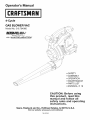
4-Cycle
GAS BLOWER VAC
Model No. 316.794980
INCREDI.PULL
TM
UNBELIEVABLE
with
STARTING
E A S E
MAX FIRE_tI[3NITION
M
•
•
•
•
•
•
SAFETY
ASSEMBLY
OPERATION
MAINTENANCE
PARTS LIST
ESPANOL, E 19
CAUTION:
Before using
this product, read this
manual and follow all
safety rules and operating
instructions.
Sears, Roebuck
and Co., Hoffman
Estates, IL 60179, U.S.A.
Visit our website" www.sears.com/craftsman
769-02360
CALIFORNIA
PROPOSITION
65 WARNING
THE ENGINE EXHAUST FROM THIS PRODUCT CONTAINS
CHEMICALS KNOWN TO THE STATE OF CALIFORNIA TO
CAUSE CANCER, BIRTH DEFECTS OR OTHER
REPRODUCTIVE HARM.
TABLE OF CONTENTS
Rules for Safe Operation ..........................
2
Warranty Information .............................
4
Know Your Unit .................................
5
Assembly Instructions ............................
6
Oil and Fuel Information ...........................
8
Starting/Stopping
Instructions ......................
9
Operating Instructions ...........................
10
Maintenance and Repair Instructions
...............
12
Cleaning and Storage ...........................
15
Troubleshooting Chart ...........................
16
Specifications
.................................
16
Repair Protection Agreement
.....................
17
Parts List .....................................
37
Service Numbers ........................
Backcover
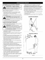
• IMPORTANT
READ ALL INSTRUCTIONS
SPARK ARRESTOR NOTE
NOTE: For users on U.S. Forest Land and in the states of
California, Maine, Oregon and Washington. All U.S. Forest
Land and the state of California (Public Resources Codes 4442
and 4443), Oregon and Washington require, by law that certain
internal combustion engines operated on forest brush and/or
grass-covered areas be equipped with a spark arrestor,
maintained in effective working order, or the engine be
constructed, equipped and maintained for the prevention of
fire. Check with your state or local authorities for regulations
pertaining to these requirements. Failure to follow these
requirements could subject you to liability or a fine. This unit is
factory equipped with a spark arrestor. If it requires
replacement, ask a Sears or other qualified service dealer to
install the Accessory Part #753-05297 Spark Arrestor Kit.
WARNING:
When using the unit, you must follow
the safety rules. Please read these instructions
before operating the unit in order to ensure the
safety of the operator and any bystanders. Please
keep these instructions for later use.
All information, illustrations, and specifications in this manual
are based on the latest product information available at the
time of printing. We reserve the right to make changes at any
time without notice.
SAFETY INSTRUCTIONS
BEFORE OPERATING
the safety rules. Please read these instructions before
operating the unit in order to ensure the safety of the
operator and any bystanders. Please keep these
instructions for later use.
• Read the instructions carefully. Be familiar with the controls
and proper use of the unit.
• Do not operate this unit when tired, ill, or under the influence
of alcohol, drugs, or medication.
• Children and teens under the age of 15 must not use the unit,
except for teens guided by an adult.
• All guards and safety attachments must be installed properly
before operating the unit.
• Inspect the unit before use. Replace damaged parts. Check for
fuel leaks. Make sure all fasteners are in place and secure.
Replace parts that are cracked, chipped, or damaged in any
way. Do not operate the unit with loose or damaged parts.
• Carefully inspect the area before starting the unit. Remove all
debris and hard or sharp objects such as glass, wire, etc.
• Clear the area of children, bystanders, and pets. At a minimum,
keep all children, bystanders, and pets outside a 50 feet (15 m.)
radius; there still may be a risk to bystanders from thrown
objects. Bystanders should be encouraged to wear eye
protection. If you are approached, stop the unit immediately.
SAFETY WARNINGS FOR GAS UNITS
• Store fuel only in containers specifically designed and
approved for the storage of such materials.
vapors can explode if ignited. Take the following
WARNING:
Gasoline is highly flammable, and its
precautions:
• Avoid creating a source of ignition for spilled fuel. Do not
start the engine until fuel vapors dissipate.
• Always stop the engine and allow it to cool before filling the fuel
tank. Never remove the cap of the fuel tank, or add fuel, when
the engine is hot. Never operate the unit without the fuel cap
securely in place. Loosen the fuel tank cap slowly to relieve any
pressure in the tank.
• Add fuel in a clean, well-ventilated outdoor area where there are
no sparks or flames. Slowly remove the fuel cap only after stopping engine. Do not smoke while adding fuel. Wipe up any spilled
fuel from the unit immediately. Always wipe unit dry before using.
• Move the unit at least 30 feet (9.1 m) from the fueling source and
•
site before starting the engine. Do not smoke or allow sparks and
open flames near the area while adding fuel or operating the unit.
WHILE OPERATING
• Never start or run the unit inside a closed room or building.
Breathing exhaust fumes can kill. Operate this unit only in a
well-ventilated outdoor area.
• To reduce the risk of injury associated with thrown objects,
wear safety glasses or goggles that are marked as meeting
ANSI Z87. standards.
• Never run the unit without the the proper equipment
attached. When using this unit, always install the
blower/vacuum tubes and vacuum bag depending on model.
Make sure the vacuum bag is completely zipped closed.
• To reduce the risk of hearing loss associated with sound level(s),
always wear ear/hearing protection when operating this unit.
• Wear heavy, long pants, boots, gloves, and a long-sleeved
shirt. Do not wear loose clothing, jewelry, short pants,
sandals, or go barefoot. Secure hair above shoulder level.
• To avoid static electricity shock, do not wear rubber gloves
or any other insulated gloves while operating this unit.
• To reduce the risk of injury associated with objects being
drawn into rotating parts, do not wear loose clothing, jewelry,
scarves, and the like. Secure hair above shoulder level.
• Wear a face or dust mask if the operation is dusty. Long
sleeve shirts are recommended.
• Use the unit only in daylight or good artificial light.
• Keep outside surfaces free from oil and fuel.
• Avoid accidental starting. Be in the starting position whenever
pulling the starter rope. The operator and unit must be in a stable
position while starting. Refer to Starting/Stopping Instructions.
• Do not set unit on any surface except a clean, hard area
while engine is running. Debris such as gravel, sand, dust,
grass, etc. could be picked up by the air intake and thrown
out by the discharge opening, damaging unit, property, or
causing serious injury to bystanders or operator.
• Use the right tool. Only use this tool for the purpose intended.
• Do not force unit. It will do the job better and with less
likelihood of injury at a rate for which it was designed.
• Do not overreach or use from unstable surfaces such as
ladders, trees, steep slopes, rooftops, etc. Always keep
proper footing and balance.
• Always hold the unit with a firm grip when operating.
• Keep hands, face, and feet at a distance from all moving parts.
Do not touch or try to stop the impeller when it is rotating. Do
notoperate
without
guards
inplace.
• Do not put any object into openings. Do not use with any
opening blocked; keep free of dirt, debris, and anything that
may reduce the air flow.
• Do not touch the engine or muffler. These parts get extremely hot
from operation. When turned off they remain hot for a short time.
• Do not operate the engine faster than the speed needed to do
the job. Do not run the engine at high speed when not in use.
• Always stop the engine when operation is delayed or when
walking from one location to another.
• Stop the engine for maintenance, repair, to install or remove
the blower tubes or vacuum attachments. The unit must be
stopped and the impeller no longer turning to avoid contact
with the rotating blades.
• Use only original equipment manufacturer replacement parts when
servicing this unit. These parts are available from your authorized
service dealer. Do not use unauthorized parts, accessories, or
attachments for this unit. Doing so could lead to serious injury to
the user, or damage to the unit, and void your warranty.
• Never use this unit for spreading chemicals, fertilizers or
other substances which may contain toxic materials.
• To reduce fire hazard, replace faulty muffler and spark
arrestor, keep the engine and muffler free from grass, leaves,
excessive grease or carbon build up.
WHILE OPERATING UNIT AS A BLOWER
• Never point the blower in the direction of people or pets, or in the
direction of windows. Always direct the blowing debris away from
people, animals, and windows. Use extra caution when blowing
debris near solid objects such as trees, automobiles, walls, etc.
WHILE OPERATING UNIT AS A VACUUM
• Avoid situations that could catch the vacuum bag on fire. Do not
operate near an open flame. Do not vacuum warm ash from fireplaces, barbecue pits, brush piles, etc. Do not vacuum discarded
cigars or cigarettes unless the cinders are completely cool.
• The unit is designed to pickup dry material such as leaves,
grass, small twigs, and bits of paper. Do not attempt to
vacuum wet debris and/or standing water as this may result
in damage to the blower/vacuum.
To avoid severe damage
to the impeller, do not vacuum metal, broken glass, etc.
OTHER SAFETY WARNINGS
• Always disconnect the spark plug before performing
maintenance or accessing movable parts.
• Never store the unit, with fuel in the tank, inside a building
where fumes may reach an open flame (pilot lights, etc.) or
sparks (switches, electrical motors, etc.).
• Allow the engine to cool before storing or transporting. Be
sure to secure the unit while transporting.
• Store the unit in a dry place, either locked up or up high to prevent
unauthorized use or damage. Keep out of the reach of children.
• Never douse or squirt the unit with water or any other liquid.
Keep handles dry, clean, and free from debris. Clean after
each use, see Cleaning and Storage instructions.
• Keep these instructions. Refer to them often and use them to
instruct other users. If you loan this unit to others, also loan
these instructions to them.
SPECIAL NOTE: Exposure to vibrations through prolonged use
of gasoline powered hand tools could cause blood vessel or
nerve damage in the fingers, hands, and joints of people prone to
circulation disorders or abnormal swelling. Prolonged use in cold
weather has been linked to blood vessel damage in otherwise
healthy people. If symptoms occur such as numbness, pain, loss
of strength, change in skin color or texture, or loss of feeling in
the fingers, hands or joints, discontinue use of this tool and seek
medical attention. An anti-vibration system does not guarantee
avoidance of these problems. Users who operate power tools on
a regular basis must closely monitor their physical condition and
the condition of this tool.
SAVE THESE INSTRUCTIONS
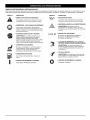
SAFETY AND INTERNATIONAL SYMBOLS
This operator's manual describes safety and international symbols and pictographs that may appear on this product.
operator's manual for complete safety, assembly, operating and maintenance and repair information.
SYMBOL
MEANING
A
SYMBOL
Read the
MEANING
• SAFETY ALERT SYMBOL
Indicates danger, warning or caution. May" be used
in coniunction with other symbols or eictographs.
• WARNING
- READ OPERATOR'S
,, ON/OFF STOP CONTROL
MANUAL
OFF Or STOP
Read the operator's manual,s) and follow all warnings
and safety instructions. --allure to do so can result iF
serious injury to the oeerator ari!!or Dystanaers
- KEEP BYSTANDERS
WARNING: Keep all bystanders, especially
children and PetS, at least 50 feet (!5 m) from the
operating area.
• WEAR EYE AND HEARING PROTECTION
WARNING: Thrown objects ana ioua noise can
cause severe eye injury and hearing loss. Wear eye
erotection meeting ANSI Z87.1 stanaaras ana ear
oroteetion when ouerating this unit. Use a ful face
snleld when neeaea.
• UNLEADED
FUEL
Always use clean, fresh unleaded fuel
AWAY
"
HOT SURFACE
WARNING
I11
Do not touch a hot muffler, gear housing or Cylinder.
You may get burned. These parts get extremely hot
,_,"_tt,_,
r, ,,
from operat on They rema n hot for a short t me affer
_11_11_11_1_1_, t he uni;cis tumed off .
• OIL
Refer to operator's
oil.
t
2
manual for the eroeer type of
3
H N Itl " CHOKE
CONTROL
1. • FULL
ChOKe
eosEIon
2. • PARTIAL choke oosition
3. • RUN cnoKe position
•
THROTTLE
CONTROL
Indicates "HIGH" or "FASTEST" speed
TWO YEAR LIMITED WARRANTY
When used and maintained according to the operator's manual, if this product fails due to a defect in material or workmanship within
two years from the date of purchase, return it to any Sears store, Sears Parts & Repair Service Center, or other Craftsman outlet for
free repair. This warranty excludes spark plug, air filter, and vacuum bag, which are expendable parts that can wear out from normal
use in less than two years. This warranty applies for only 30 days from the date of purchase if this product is ever used for
commercial or rental purposes.
This warranty gives you specific legal rights, and you may also have other rights which vary from state to state.
Sears, Roebuck and Co., Hoffman Estates, IL 60179
California / EPA Emission Control Warranty Statement
Your Warranty Rights and Obligations
The California Air Resources Board, The Environmental Protection Agency and Sears, Roebuck and Co., are pleased to explain the
emission control system warranty on your 2005 and later small off-road engine. New small off-road engines must be designed, built
and equipped to meet stringent anti-smog standards. Sears, Roebuck and Co. must warrant the emission control system on your
small off-road engine for the periods of time listed below provided there has been no abuse, neglect or improper maintenance of your
small off-road engine.
Your Emission control system may include parts such as the carburetor or fuel-injection system, the ignition system, and catalytic
converter. Also included may be hoses, belts, connectors and other emission-related assemblies.
Where a warrantable condition exists, Sears will repair your small off-road engine at no cost to you including diagnosis, parts and
labor.
The 2005 and later small off-road engines are warranted for two years. If any emission-related
defective, the part will be repaired or replaced by Sears.
part on your engine is
Owner's Warranty Responsibilities
• As the small off-road engine owner, you are responsible for the performance of the required maintenance listed in your operator's
manual. Sears recommends that you retain all receipts covering maintenance on your small off-road engine, but Sears cannot deny
warranty solely for the lack of receipts or for your failure to ensure the performance of all scheduled maintenance.
• As the small off-road engine owner, you should however be aware that Sears may deny you warranty coverage if your small offroad engine or a part has failed due to abuse, neglect, improper maintenance or unapproved modifications.
• You are responsible for presenting your small off-road engine to a Sears authorized service center as soon as problem exists. The
warranty repairs should be completed in a reasonable amount of time, not to exceed 30 days.
• If you have any questions regarding your warranty rights and responsibilities, you should call 1-800-4-MY-HOME
®.
Manufacturer's Warranty Coverage
• The warranty period begins on the date the engine or equipment is delivered to the retail purchaser.
• The manufacturer warrants to the initial owner and each subsequent purchaser, that the engine is free from defects in material and
workmanship which cause the failure of a warranted part for a period of two years.
• Repair and replacement of warranted part will be performed at no charge to the owner at an authorized Sears service center. For
the nearest location please contact Sears at: 1-800-4-MY-HOME
®.
• Any warranted part which is not scheduled for replacement, as required maintenance or which is scheduled only for regular
inspection to the effect of "Repair or Replace as Necessary" is warranted for the period. Any warranted part which is scheduled for
replacement as required maintenance will be warranted for the period of time up to the first scheduled replacement point for that
part.
• The owner will not be charged for diagnostic labor which leads to the determination that a warranted part is defective if the
diagnostic work is performed at an authorized Sears Service Center.
• The manufacturer is liable for damages to other engine components caused by the failure of a warranted part still under warranty.
• Failures caused by abuse, neglect or improper maintenance are not covered under warranty.
• The use of add-on or modified parts can be grounds for disallowing a warranty claim. The manufacturer is not liable to cover failures
of warranted parts caused by the use of add-on or modified parts.
• In order to file a claim, go to your nearest authorized Sears Service Center. Warranty service or repairs will be provided at all
authorized Sears Service Centers.
• Any manufacturer approved replacement part may be used in the performance of any warranty maintenance or repair of emission
related parts and will be provided without charge to the owner. Any replacement part that is equivalent in performance or durability
may be used in non-warranty maintenance or repair and will not reduce the warranty obligations of the manufacturer.
• The following components are included in the emission related warranty: engine, air filter, carburetor, primer, fuel lines, fuel pick
up/fuel filter, ignition module, spark plug and muffler.
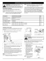
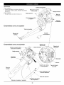
APPLICATIONS
Asablower:
• Cleaning
yards,garages,
driveways,
porches,
patios,around
walls,fencesandmore
Asavacuum:
• Picking
upleaves
andotherlightdebris
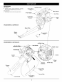
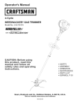
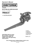
Throttle Control
StarterRope
Grip
Rear Handle
Front Handle
Spark Plug
On/Off Stop
Control
_<-_
Fuel
Cap
i
I
Assembled
as a Blower
Blower Tube
Blower
Outlet
Assembled
Concentrator
Nozzle
as a Vacuum
Air Filter Cover
Shoulder Strap
Attachment Points
Rear Handle
Muffler
Cover
Front Handle
Muffler
Vacuum
Door
Primer
Bulb
Vacuum
Bag Hook
Vacuum
Tube
Vacuum Bag
Zipper
Vacuum Bag
Vacuum Inlet
Vacuum Bag
Adapter
Oil Filler Cap
ASSEMBLING
UNITASABLOWER
BlowerTubeAssembly
stop the engine and allow the impeller to stop
WARNING:
To or
prevent
serious
personal injury,
before
attaching
removing
tubes.
or damage to the unit, the blower tube must be
WARNING:
prevent this
serious
personal
injury
installed
while To
operating
unit as
a blower.
NOTE:
If the unit was assembled as a vacuum unit, remove all
vacuum parts and store away in a secure place for
later use.
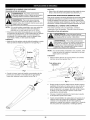
• Please note this unit comes with a high pressure concentrator
nozzle. This nozzle should be used when there is a need to
blow in a limited or concentrated area. In general uses, such
as leaf or grass blowing, the nozzle should not be used.
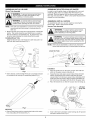
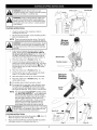
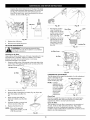
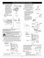
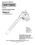
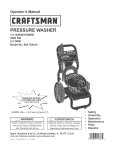
Installing Blower Tube
Install the blower tube over the blower outlet and push it on
until both tabs snap into place (Fig. 1).
ASSEMBLING THE GUTTER CLEAN-OUT ADAPTER
In order to use the gutter clean-out attachment kit, you must
install the gutter clean-out adapter (Part #753-05231 not
included). Push the adapter onto the blower outlet until both
tabs snap into place (Fig. 1). Refer to the Gutter Attachment Kit
manual for more information.
ASSEMBLING
UNIT AS A VACUUM
To assemble the unit as a vacuum, begin by removing the
blower tube. Refer to the previous section.
Vacuum Tube Assembly
I
stop the engine and allow the impeller to stop
WARNING:
prevent
serious
personal injury,
before attachingTo or
removing
tubes.
I
I
damage to the unit, always install vacuum tubes and I
the
vacuum bag,
makeserious
sure the
vacuuminjury
bag is
WARNING:
To and
prevent
personal
or I
_
cO v2tpped
z cosed
when
operat
ngthsunt
NOTE:
If the unit was assembled as a blower unit, remove the
blower tube and store away in a secure place for later use.
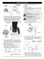
Lower Vac Tube
Arrows
Upper Vac Tube
Fig. 3
Outlet
Fig. 1
• When desired, insert the High Pressure Concentrator Nozzle
to increase the air velocity for demanding tasks (Fig. 2).
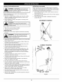
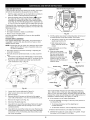
Installation
1.
2.
3.
Align the small arrow on the lower vacuum tube with the
arrow on the upper vacuum tube (Fig. 3).
Grasp the lower and upper vacuum tubes firmly with both
hands, and push the lower vacuum tube into the upper
vacuum tube. Turn the lower vacuum tube clockwise until it
snaps into place and locks. When properly assembled, the
dot on the lower tube aligns with the dot on the upper tube.
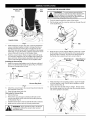
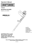
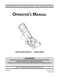
Place the blower/vac so that the vacuum door is facing up.
Vacuum
Locking
Clip
J
Fig. 2
Removing
• Remove the blower tube by pressing both tabs at the same
time and pulling off the blower (Fig. 1).
Fig. 4
Insert a flat head screwdriver under locking clip, lift upward
and open vacuum door (Fig. 4).
Vacuum Tube
Groove
Flat
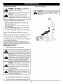
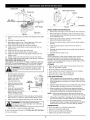
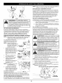
INSTALLING THE SHOULDER STRAP
WARNING:
To avoid serious personal injury,
never attempt to start the unit when standing with
the unit clipped to the shoulder strap. Always
follow the starting procedures as described in the
Starting/Stopping
Instructions section.
_
Tabs
1.
2.
Push the strap through the center of the buckle.
Pull the strap over the cross bar and down through the slot
in the buckle (Fig. 7).
Align
Arrows
Impeller Intake
Fig. 5
5.
6.
Clip
While holding the vacuum door open, insert the assembled
vacuum tube (put together in Step 2). Arrange the tube so
the flat area faces the vacuum door. The grooves on the
side of the tube will line up with the small tabs in the impeller
intake (Fig. 5). From the exterior, align the small arrow on the
vacuum tube with the arrow on the impeller intake.
Push the vacuum tube in firmly and grip it with both hands.
Turn the tube clockwise as far as possible until it snaps into
place and locks. When properly assembled, the dot on the
vacuum tube will align with the dot on the impeller intake.
Fig. 7
3.
Snap the clip on to the support fittings on the front or back
of the handle. Clip to the front portion of the handle when
using the unit as a blower, and clip to the back portion of
the handle when using the unit as a vacuum (Fig. 8).
Attach Here for
Blowing
Installing the Vacuum Bag
7. Install the vacuum bag adapter over the blower outlet and
push on it until both tabs snap into place (Fig. 6). Position
the bag so it hangs below the unit.
Attach Here for
Vacuuming
Elbow
_o
Fig. 8
4.
Vacuum
Bag Hook
Fig. 6
8.
Attach the vacuum bag to the vacuum bag hook located at
the underside of the unit.
5.
While standing in the operating position, adjust the length
to fit the operator's size. Pull the tab to lengthen, pull the
strap to shorten (Fig. 9).
Do not allow the shoulder strap to dangle. Always unclip
the shoulder strap from the unit when the shoulder strap is
not on the operator's shoulder.
9. Keep the bag zipped and shut.
Removing the Vacuum Bag
1. Unhook the bag.
2. Remove the vacuum bag by pressing both tabs on the
vacuum bag elbow at the same time and pulling the bag
off the blower (Fig. 6).
3. Install the blower tube in order to assemble the unit as a blower.
4.
Make sure the vacuum door is securely latched shut.
configuration without the vacuum door secured
WARNING:
Never operate the unit in the blower
and latched shut.
Fig. 9
WARNING: OVERFILLING OIL CRANKCASE MAY
CAUSE SERIOUS PERSONAL INJURY. Check and
maintain the proper oil level in the crank case; it is
important and cannot be overemphasized. Check
the oil before each use and change it as needed.
See Changing the Oil.
RECOMMENDED OIL TYPE
Using the proper type and weight of oil in the crankcase is
extremely important. Check the oil before each use and
change the oil regularly. Failure to use the correct oil, or using
dirty oil, can cause premature engine wear and failure.
Use a high-quality SAE 30 weight oil of API (American
Petroleum Institute) service class SF, SG, SH.
ADDING OIL TO CRANKCASE: INITIAL USE
Using Blended Fuels
If you choose to use a blended fuel, or its use is unavoidable,
follow recommended precautions:
• Always use fresh unleaded gasoline
• Use a gas stabilizer fuel additive
• Drain tank and run the engine dry before storing unit
Using Fuel Additives
The use of a gas stabilizer will inhibit corrosion and minimize
the formation of gum deposits. Using a fuel additive can keep
fuel from forming harmful deposits in the carburetor for up to
six (6) months. Add 0.8 oz. (23 ml.) of fuel additive per gallon of
fuel according to the instructions on the container. NEVER add
fuel additives directly to the unit's gas tank.
outdoor area. Wipe up any spilled fuel immediately. I
WARNING: Add fuel in a clean, well ventilated
I
Avoid creating a source of ignition for spilt fuel. Do
not start the eng ne unt fue vapors d ss pate.
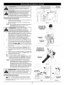
NOTE: This unit is shipped without oil. In order to avoid
damage to the unit, put oil in the crankcase before you
attempt to start the unit.
Your unit is supplied with one 3.04
fluid oz. (90 ml.) bottle of SAE 30
SF, SG, SH oil (Fig. 10).
NOTE: Save the empty oil bottle.
It can be used to measure
the correct amount during
future oil changes. See
Changing the Oil.
1.
,__
WARNING: Gasoline is extremely flammable.
Ignited vapors may explode. Always stop the engine
and allow it to cool before filling the fuel tank. Do
not smoke while filling the tank. Keep sparks and
open flames at a distance from the area.
Funnel
Spout
Fig. 10
Unscrew the top of the bottle
FUELING THE UNIT
1. Remove the fuel cap (Fig. 13).
seal covering the opening.
Replace the top. Next, cut
the tip off the funnel spout
(Fig. 10).
from fuel spray. Never operate the unit without the
WARNING:
Remove
fuel cap slowly to avoid injury
fuel cap securely
in place.
2.
Tip unit so that the back of
the engine is facing up in a
vertical position.
3.
4.
Pour the entire bottle of oil _.
into the oil fill hole (Fig. 12).
NOTE:
5.
Fig. 11
Remove the oil fill plug from
the crankcase (Fig. 11).
Never add oil to the fuel
or fuel tank.
Wipe up any oil that may
have spilled and reinstall the
oil fill plug.
Check oil before each use and
change as needed. Refer to
Checking the Oil Level.
RECOMMENDED
FUEL TYPE
_:_
Place the gas container's spout into the fill hole on the fuel
tank (Fig. 13) and fill the tank.
NOTE: Do not overfill the tank.
3.
Wipe up any gasoline that may have spilled.
4.
Reinstall the fuel cap.
5.
Move the unit at least 30 ft. (9.1 m) from the fueling source
and site before starting the engine.
NOTE: Dispose of the old gasoline in accordance
State and Local regulations.
q
Fig. 12
Old fuel is the primary reason for improper unit performance.
Be sure to use fresh, clean, unleaded gasoline.
NOTE: This is a four cycle engine. In order to avoid damage to
the unit, do not mix oil with gasoline.
Definition of Blended Fuels
Today's fuels are often a blend of gasoline and oxygenates
such as ethanol, methanol or MTBE (ether). Alcohol-blended
fuel absorbs water. As little as 1% water in the fuel can form
acids when stored. Use fresh fuel (less than 60 days old), when
using alcohol-blended fuel.
Fig. 13
to Federal,
I
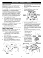
Primer Bulb
Choke Lever -,
WARNING: Operate this unit only in a wellventilated outdoor area. Carbon monoxide exhaust
fumes can be lethal in a confined area.
\
WARNING: Avoid accidental starting. Make sure
you are in the starting position when pulling the
starter rope (Fig. 15 or 16). To avoid serious injury,
the operator and unit must be in a stable position
while starting.
STARTING INSTRUCTIONS
1.
Check the oil level in the crankcase,
Checking the Oil Level.
2.
Fill the fuel tank with fresh, clean unleaded gasoline.
Refer to Fueling the Unit.
NOTE:
Refer to
Fig. 14
There is no need to turn the unit on. The On/Off
Stop Control is in the ON ( I) position at all times.
Blower
Starting
Position
WARNING: To avoid serious personal injury, always
remove the vacuum bag prior to refueling the unit.
The bag may become a fire hazard when saturated
with fuel.
Fully press and release the primer bulb 10 times,
slowly. Some amount of fuel should be visible in
the primer bulb and fuel lines (Fig. 14). If you can't
see fuel in the bulb, press and release the bulb as
many times as it takes before you can see fuel in it.
i
4.
Place the choke lever in Position
i
5.
Crouch in the blower starting position (Fig. 15) or
stand in the vacuum starting position (Fig. 16). Move
the throttle control to the fast position (,_) (Fig. 18).
Pull the starter rope out with a smooth and steady
motion 5 times.
i
i
6.
7.
Place the choke lever in Position
i
8.
Allow the engine to warm up for 15 to 30 seconds.
9.
Starter
1 (Fig. 14).
Throttle Control
2 (Fig. 14).
Fig. 15
Pull the starter rope out with a smooth and steady
motion 1 to 4 times to start the engine.
Place the choke lever in Position
unit is ready for use.
Rope
Vacuum
Starting
Position
3 (Fig. 14). The
IF...The engine does not start, go back to step 3.
IF...The
the
out
the
engine fails to start after a few attempts, place
choke lever in Position 3. Pull the starter rope
with a smooth and steady motion 3 to 8 times-engine should start. If not, pull 3 to 8 more times.
NOTE:
The unit uses the Incredi-Pull TM starting system
with MAX FIRE IGNITION TM , which significantly
reduces the effort required to start the engine.
You must pull the starter rope out far enough to
hear the engine attempt to start. There is no
need to pull the rope briskly-- there is no harsh
resistance when pulling. Be aware that this
starting method is vastly different from (and
much easier than) what you may be used to.
IMPORTANT: Move the throttle to idle, or shut the
unit off, when not operating, when setting the unit
down, or when performing maintenance.
STOPPING INSTRUCTIONS
1. Move the throttle control to the idle position (_)
Allow the engine to cool down by idling.
2.
Starter
Rope
Fig. 16
J
Start/On
(I)
(Fig. 17).
Press and hold On/Off Stop Control in the OFF (O) position
until engine comes to a complete stop (Fig. 14)
Throttle
Control
/
Fig. 17
Fig. 18
HOLDING
THEBLOWER/VACUUM
OPERATING
AS A BLOWER
Please note this unit comes with a high pressure concentrator
nozzle. This nozzle should be used when there is a need to blow
in a limited or concentrated area. In general uses, such as leaf or
grass blowing, the nozzle should not be used.
1 Use the blower for trees, shrubs, flower beds and hard-toclean areas (Fig. 19).
2. Use the unit around buildings and for other normal cleaning
procedures (Fig. 19).
3. Use the blower around walls, overhangs, fences and
screens (Fig. 20).
WARNING- Hot
Surface:
After starting the
unit, always stand on the left side of the unit to
operate it as shown in Figure 20. Do not operate
the unit as shown in figure 19.
Before operating the unit, stand in the operating position.
Check for the following:
• Operator is wearing proper clothing, such as boots, safety
glasses or goggles, ear/hearing protection, gloves, long
pants and long sleeve shirt
• If the conditions are dusty, the operator is wearing a dust
mask or face mask
INCORRECT
POSITION
goggles or safety glasses at all times when
_1
ARNING: To avoid serious personal injury, wear
in°peratdustynglocations.th
sun t. Wear a face mask or dust mask
• The unit is in good working condition
• The tubes are in place and secure
OPERATING TIPS
• Be sure the vacuum bag is zipped closed before operating
the unit.
damage to the unit, make sure blower tubes or
WARNING:
serious
personal
injury or
vacuum tubes To
andprevent
the vacuum
bag
are in place
before you operate the unit.
• Assure the unit is not directed at anybody or any loose debris
before starting the unit.
Fig. 19
• Verify that the unit is in good working condition. Make sure
the tubes are in place and secure.
• Always hold the unit securely when operating. Keep a firm
grip on both the front and rear handles.
• To reduce the risk of hearing loss associated with sound
level(s), hearing protection is required.
• Operate power equipment only at reasonable hours-- not
early in the morning or late at night when people might be
disturbed. Comply with times listed in local ordinances.
Usual recommendations are 9:00 am to 5:00 pro, Monday
through Saturday.
• To reduce noise levels, limit the number of pieces of
equipment used at any one time.
• To reduce noise levels, operate power blowers at the lowest
possible speed to do the job.
• Check your equipment before operation,
muffler, air intakes and air filters.
CORRECT
POSITION
especially the
• Use rakes and brooms to loosen debris before blowing.
• In dusty conditions, slightly dampen surfaces or use a mister
attachment when water is available.
• Conserve water by using power blowers instead of hoses for
many lawn and garden applications, including areas such as
screens, patios, grills, porches, and gardens.
• Watch out for children, pets, open windows or freshly
washed cars, and blow debris safely away.
• Use the full blower nozzle extension so the air stream can
work close to the ground.
• Clean up after using blowers and other equipment. Dispose
of debris appropriately.
Fig. 20
10
OPERATING
ASAVACUUM
shake out dust and debris.
4.
unit, always stand on the left side of the unit to
operate it as shown
in Figure 21.
WARNING
- Hot Surface:
After starting the
Zip close and reinstall the vacuum bag.
WARNING: To avoid serious personal injury, turn
off the unit and allow the impeller to stop before
opening vacuum door or installing or removing
vacuum bag.
WARNING: To prevent serious personal injury or
damage to the unit, always install vacuum tubes,
vacuum bag and make sure the vacuum bag is
completely zipped closed when operating this unit as
a vacuum.
Check for the following before operating the unit:
• Operator is wearing proper clothing, such as boots, safety
glasses or goggles, ear/hearing protection, gloves, long
pants and long sleeve shirt
• If the conditions are dusty, operator is equipped with a dust
mask or face mask
• The unit is in good working condition-- the vacuum tubes
and vacuum bag are in place and secure.
• The vacuum shoulder strap is in place and correctly adjusted.
Operation Procedure
Use the unit for vacuuming up light debris like leaves and
paper.
Hold the vacuum, tilting the suction tube slightly (2-4 inches or
50-100 mm above the ground), and use a sweeping action to
collect light debris (Fig. 21). The debris will flow into the
vacuum bag. Items such as small leaves and small twigs will
be mulched as they pass through the fan housing, allowing the
vacuum bag to hold more debris.
When the bag is full, suction will noticeably decrease. Turn off
the unit and allow the impeller to stop before you unzip the
bag. Unzip the bag and empty the contents before continuing.
Refer to Emptying the Vacuum Bag.
Emptying the Vacuum Bag
1. Remove the bag from the vacuum bag hook.
o©
Fig. 21
WARNING: To avoid serious personal injury, never
unzip the vacuum bag without stopping the unit
f rst.
WARNING: As a vacuum, the unit is designed to
pick up dry material such as leaves, grass, small twigs
and bits of paper. To avoid serious personal injury, do
not attempt to vacuum wet debris and/or standing
water as this may result in damage to the blower/
vacuum. To avoid severe damage to the impeller, do
not vacuum metal, broken glass or similar items.
WARNING: Avoid situations that could catch the
vacuum bag on fire. Do not operate near an open
flame. Do not vacuum warm ash from fireplaces,
barbecue pits, brush piles, etc. Do not vacuum
discarded cigars or cigarettes unless the cinders
are completely cool.
WARNING: When the upper and lower vacuum
tubes are removed, make sure the vacuum door is
snapped closed and secured before using the unit, to
avoid injury from the impeller.
2.
While wearing eye protection and a dust mask, unzip the
vacuum bag and empty the contents into a garbage bag or
container.
3.
Turn the bag inside out after initial emptying and vigorously
11
I
I
WARNING:
Toprevent
serious
injury,
never
I
NOTE:
perform maintenance or repairs with unit running.
Always service and repair a cool unit. Disconnect the
spark pug w re to ensure that the un t cannot start.
In order to assure peak performance of your engine, inspection
of the engine exhaust port may be necessary after 50 hours of
operation. If you notice lost RPM, poor performance or general
lack of acceleration, this service may be required. If you feel
your engine is in need of this inspection, refer service to a
Sears or other qualified service dealer for repair. DO NOT
attempt to perform this process yourself as engine damage
may result from contaminants involved in the cleaning process
for the port.
MAINTENANCE SCHEDULE
Perform these required maintenance procedures at the
frequency stated in the table. These procedures should also
be a part of any seasonal tune-up.
NOTE:
Maintenance, replacement, or repair of the emission
control devices and system may be performed by a
Sears or other qualified service dealer.
Some maintenance procedures may require special tools
or skills. If you are unsure about these procedures take
your unit to a Sears or other qualified service dealer.
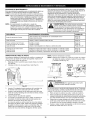
FREQUENCY
MAINTENANCE
Before starting engine
Fill fuel tank with fresh fuel
Check oil
p. 8
p. 12
Every 10 hours
Clean and re-oil air filter
p. 13
1st change at 10 hours
2nd change at 25 hours
Every 25 hours after
Change oil
Change oil
Clean spark arrestor and change oil
p. 12
p. 12
p. 15&12
10 hours on new engine
Every 25 hours
Check rocker arm to valve clearance and adjust
Check rocker arm to valve clearance and adjust
p. 14
p. 14
Every 25 hours
Check spark plug condition and gap
p. 15
CHECKING THE OIL LEVEL
The importance of checking and maintaining
in the crankcase cannot be overemphasized.
each use:
REQUIRED
SEE
Max Oil Fill Line
the proper oil level
Check oil before
1.
Stop the engine and allow oil to drain into the crankcase.
2.
Place the engine on a level surface (Fig. 22).
Oil Fill Plug
ft4_/_
o.,o
Oil Fill Hole "__
Fig. 23
CHANGING
_
I
Fig. 24
THE OIL
handling unit.
ARNING: Wear gloves to prevent injury when
For a new engine, change the oil after the first 10 hours of
operation. Change the oil while the engine is still warm. The oil
will flow freely and carry away more impurities.
3.5"
Fig. 22
3.
Raise the rear of the unit 3.5 inches to get a proper oil level
reading.
4.
Clean the area around the dipstick before removing it. Keep
dirt, grass clippings, and other debris out of the engine.
5.
Remove the oil fill plug.
6.
Look into the oil fill hole (use a flashlight if needed). The oil
should be just touching the innermost thread (Fig. 23).
7.
If the oil level is not touching the innermost thread on the
oil fill hole, add a small amount of oil to the oil fill hole and
recheck (Fig. 23). Repeat this procedure until the oil level
reaches the innermost thread on the oil fill hole.
NOTE:
Do not overfill the unit.
NOTE:
Make sure the O-ring is in place on the oil fill plug when
checking and changing the oil (Fig. 24).
1.
Remove the oil fill plug.
2.
Pour the oil out of the oil fill hole and into a container by
tipping the unit to a
vertical position (Fig. 25).
Allow ample time for
complete drainage.
3.
Wipe up any oil residue
on the unit and clean up
any oil that may have
spilled. Dispose of the
oil according to Federal,
State and local
regulations.
4.
Refill the crankcase with
3.04 fluid ounce (90 ml)
of SAE 30 SF, SG, SH oil.
NOTE: Use the bottle and
spout saved from
initial use to
12
Fig. 25
I
I
measure
thecorrectamount
ofoil.Thetopofthelabel
onthebottlemeasures
approximately
3.04ounces
(90
ml)(Fig.26).Check
thelevel,SeeChecking
theOil
Level.
Ifthelevelislow,addasmallamount
ofoiland
recheck.
Donotoverfill(Fig.23).
Fig. 29
Fig. 26
5.
Replace the oil fill plug.
6.
Reconnect the spark plug boot.
AIR FILTER MAINTENANCE
7.
Reinstall the air filter
cover. Position the
slots on the top of the
air filter cover onto the
tabs at the top of the
back plate (Fig. 31).
8.
Swing the cover down
until the tab on the air
filter backplate snaps
into place in the slot
on the air filter cover
(Fig. 32).
Fig. 30
Tabs
Back Plate
Fig. 31
always turn the unit off and allow it to cool before
WARNING:
To avoidit. serious personal injury,
you clean or service
_l
Cleaning the Air Filter
Clean and re-oil the air filter every 10 hours of operation. It is an
important item to maintain. Failure to maintain your air filter
properly can result in poor performance or can cause
permanent damage to your engine.
1.
Open the air filter cover. Push the tab on the under side of the
cover inward. Then pull the air filter cover out and up from the
bottom of the cover (Fig. 27).
Air Filter Cover
Fig. 32
Air Filter
CARBURETOR
The idle speed of the engine is adjustable. An idle adjustment
screw is between the air
filter cover and the engine
Idle Adjustment Screw
starter housing (Fig. 33).
f
NOTE: Careless
adjustments can
seriously damage
your unit. A Sears
or other qualified
service dealer
should make
carburetor
Tab
Fig. 27
2.
Remove the air filter (Fig. 27).
3.
Wash the filter in detergent and water (Fig. 28). Rinse the
filter thoroughly and allow it to
dry.
4.
Apply enough clean SAE 30
motor oil to lightly coat the filter
(Fig. 29).
5.
Squeeze the filter to spread and
remove excess oil (Fig. 30).
6.
Replace the filter (Fig. 31).
NOTE:
ADJUSTMENT
adjustments.
Fig. 33
Check Fuel
Old fuel is usually the reason for improper unit performance.
Drain and refill the tank with fresh fuel prior to making any
adjustments. Refer to Oil and Fuel Information.
Clean Air Filter
The condition of the air filter is important to the operation of
the unit. A dirty air filter will restrict air flow. This is often
mistaken for an out of adjustment carburetor. Check the
condition of the air filter before adjusting the idle speed screw.
Refer to Air Filter Maintenance.
If the unit is operated
without the air filter, you will
VOID the warranty.
Fig. 28
13
View Of The Rear Engine Cover
Adjust Idle Speed Screw
If, after checking the fuel and cleaning the air filter, the engine
still will not idle, adjust the idle speed screw as follows:
1.
Start the engine and let it run at a high idle for a minute to
warm up. Refer to Starting/Stopping
Instructions.
2.
Move the throttle control to the idle position ('_)
and let
the engine idle. If the engine stops, insert a small phillips
screwdriver in between the Air Filter Cover and the Engine
Cover (Fig. 33). Turn the idle speed screw in, clockwise, 1/8
of a turn at a time (as needed) until the engine idles smoothly.
Remove
Remove
Screws
J
Screws
Checking the fuel, cleaning the air filter, and adjusting the idle
speed should solve most engine problems. If not and all of the
following are true:
• the engine will not idle
• the engine hesitates or stalls on acceleration
• there is a loss of engine power
Have the carburetor adjusted by a Sears or other qualified
service dealer.
Fig. 35
11. Pull the starter rope slowly to bring the piston to the top of
its travel (known as top dead center). Check that:
ROCKER ARM CLEARANCE
This requires disassembly of the engine. If you feel unsure or
unqualified to perform this, take the unit to a Sears or other
qualified service dealer
• The piston is at the top of its travel while looking in the
spark plug hole (Fig. 37)
• Both rocker arms move
freely, and both valves are
closed.
NOTE: Inspect the valve to rocker arm clearance with a feeler
gauge after the first 10 hours of operation and every
25 hours of operation.
Rocker
Arm
Cover
If these statements are not true,
repeat this step.
• The engine must be cold when checking or adjusting the
rocker arm clearance.
12. Slide the feeler gauge
between the rocker arm and
the valve return spring.
Measure the clearance
between the valve stem and
rocker arm (Fig. 37 & 38).
Measure both the intake and
exhaust valves.
• This task should be performed inside, in a clean, dust free
area.
1. Remove the 2 handle screws with flat blade or T20 torx head
screwdriver, while holding the nuts with 3/8" nut driver (Fig. 34).
2. Remove top bolt located near starter rope handle with
tools mentioned in step 1 (Fig. 34).
Spark
Plug
Hole
Fig. 36
INTAKE
Adjusting Nuts
Rocker Arms
Remove
Screws
EXHAUST
\
/@
Feeler Gauge
Loosen
Screws
@
Spark Plug
Hole
Fig. 37
Fig. 34
3.
4.
5.
6.
Loosen the 3 screws indicated in Figure 34.
Open vacuum door, prop open with hand.
Remove handle.
Remove the five (5) screws on the back of the engine
cover with a Flat-blade or T-25 Torx screwdriver (Fig. 35).
7.
Remove the engine cover (Fig. 35).
8.
Disconnect the spark plug wire.
9.
Clean dirt from around the spark plug. Remove the spark
plug from the cylinder head by turning a 5/8 in. socket
counterclockwise.
The recommended clearance for both intake and exhaust is
.003 - .006 in. (.076 - 0.152 mm). Use a standard automotive
.005 in. (0.127 mm) feeler gauge. The feeler gauge should slide
between the rocker arm and valve stem with a slight amount of
resistance, without binding. See Figures 37 and 38.
13. If the clearance is not within specification:
a. Turn the adjusting nut using a 5/16 inch (8 mm) wrench or
nut driver (Fig. 38).
• To increase clearance, turn the adjusting nut
counterclockwise.
• To decrease clearance, turn the adjusting nut clockwise.
10. Clean dirt from around the rocker arm cover. Remove the
screw holding the rocker arm cover with a large flat blade
screwdriver or Torx T-25 bit (Fig. 36). Remove the rocker
arm cover and gasket.
b. Recheck both clearances, and adjust as necessary.
14. Reinstall the rocker arm cover using a new gasket. Torque
the screw to 20-30 in•lb (2.2-3.4 N•m).
14
Muffler
Adjusting Nut
Spark Arrestor Screen
Rocker Arm
_
?
Diverter
T-25 Screw
_
"\/
.003-.006in.
(.076-.152 mm)
Slot
/
q_
T-20 Screw
Fig. 40
SPARK ARRESTOR MAINTENANCE
Valve Stem
Fig. 38
15. Check the spark plug and reinstall. See Replacing the Spark
Plug.
1.
2.
Remove the rear engine cover. See RockerArm Clearance.
With a flat blade screwdriver or Torx T-20 bit and a T-25
bit, remove the screws attaching the spark arrestor diverter
to the muffler (Fig. 40).
3.
Pull the the spark arrestor diverter out of the muffler.
Remove the spark arrestor diverter.
4.
Remove the spark arrestor screen from the spark arrestor
diverter.
5.
Clean the spark arrestor screen with a wire brush or
replace it.
6.
Reinstall the spark arrestor screen, spark arrestor diverter
and screws.
16. Reinstall the spark plug wire.
17. Reinstall the engine cover. Check alignment of the cover
before tightening the screws. Tighten screws.
18. Push rear end of handle into rear screw location.
19. Slide screw through plastic housing and handle. (Do not
tighten screw.)
20. Open vacuum door, prop open with hand.
21. Push front end of handle into front screw location.
22. Slide front handle screw through plastic housing. (Do not
tighten screw.)
23. Tighten screw near switch and near vacuum door hinge.
24. Tighten handle screws while holding nuts with 3/8" nut driver.
REPLACING THE SPARK PLUG
Use a replacement part number 753-05255 or Champion spark plug,
#RDZ19H. The correct spark gap is 0.025 in. (0.655 mm.). Remove
the plug after every 25 hours of operation and check its condition.
_1
1.
2.
3.
STORAGE
• Never store the unit with fuel in the tank where fumes may
reach an open flame or spark.
• Allow the engine to cool before storing.
• Lock up the unit to prevent unauthorized use or damage.
• Store the unit in a dry, well-ventilated area.
• Store the unit out of the reach of children.
electrodes. Grit in the engine could damage the
ARNING: Do not sand blast, scrape or clean
cylinder.
Stop the engine and allow it
to cool. Remove the five (5)
screws on the back of the
engine cover with a Flathead or T-25 Torx
screwdriver (Fig. 35).
Grasp the plug wire firmly
and pull the cap from the
spark plug.
LONG TERM STORAGE
1. Drain all gasoline from the gas tank into a container. Do not
use gas that has been stored for more than 60 days. Dispose
of the old gasoline in accordance to Federal, State, and Local
regulations.
0.025 in.
(0.655 mm.)
Clean dirt from around the
spark plug. Remove the
spark plug from the cylinder
head by turning a 5/8 in.
socket counterclockwise.
Start the engine and allow it to run until it stalls. This ensures
that all gasoline has been drained from the carburetor.
3.
Allow the engine to cool. Remove the spark plug and put 5
drops of high quality motor oil into the cylinder. Pull the starter
rope slowly to distribute the oil. Reinstall the spark plug.
NOTE:
Replace cracked, fouled or dirty spark plug. Set the spark
gap at 0.025 in. (0.655 mm.) using a feeler gauge (Fig. 39).
5.
Install a correctly-gapped
spark plug in the cylinder head.
always turn your unit off and allow it to cool before
WARNING:
To avoid
you
clean or service
it. serious personal injury,
Turn the 5/8 in. socket clockwise
2.
Fig. 3g
4.
_1
7. Reinstall the rear engine cover.
CLEANING
Use a small brush to clean off the outside of the unit. Do not
use strong detergents. Household cleaners that contain
aromatic oils such as pine and lemon, and solvents such as
kerosene, can damage plastic housing or handle. Wipe off any
moisture with a soft cloth.
Remove the spark plug and drain all of the oil from the
cylinder before attempting to start the blower after storage.
4.
Change the oil, referring to Changing the Oil. Dispose of the
old oil in accordance to Federal, State and Local regulations.
5.
Thoroughly clean the unit and inspect for any loose or
damaged parts. Repair or replace damaged parts and tighten
loose screws, nuts or bolts. The unit is ready for storage.
TRANSPORTING
• Allow the engine to cool before transporting.
• Secure the unit while transporting.
• Drain the gas tank before transporting.
• Tighten gas cap before transporting.
until snug.
If using a torque wrench torque to: 110-120 in.°lb. (12.3-13.5 Nora}
Do not over tighten.
15
CAUSE
Empty fuel tank
Primer bulb wasn't pressed enough
Old fuel
Fouled spark plug
Plugged spark arrestor
ACTION
Fill fuel tank with new fuel
Press primer bulb fully and slowly 10 times
Drain gas tank and add fresh fuel
Replace the spark plug
Clean or replace spark arrestor
CAUSE
Air filter is plugged
Old fuel
Improper carburetor adjustment
ACTION
Replace or clean the air filter
Drain gas tank and add fresh fuel
Adjust carburetor
CAUSE
Old fuel
Improper carburetor adjustment
Dirty air filter
Plugged spark arrestor
ACTION
Drain gas tank and add fresh fuel
Take to a Sears or other qualified service dealer for adjustment
Clean or replace the air filter
Clean or replace spark arrestor
CAUSE
Old fuel
Improper carburetor adjustment
Fouled spark plug
Plugged spark arrestor
ACTION
Drain gas tank and add fresh fuel
Take to a Sears or other qualified service dealer for adjustment
Replace the spark plug
Clean or replace spark arrestor
NOTE:
For repairs beyond the minor adjustments listed above, contact your nearest Sears Parts & Repair center (1-800-4-MY-HOME
or other qualified service dealer.
®}
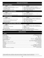
Engine Type ...............................................................................................................................................................
Air-Cooled, 4-Cycle
Displacement .................................................................................................................................................................
1.8 cu. in. (29 cc)
Vacuum Operating RPM ..........................................................................................................................................................
6,800+ rpm
Blower Operating RPM .............................................................................................................................................................
7,200+ rpm
Idle Speed RPM ...........................................................................................................................................................
3,200 - 4,400 rpm
Ignition Type .........................................................................................................................................
Electronic MAX FIRE IGNITION TM
Ignition Switch ..............................................................................................................................................................
Momentary Switch
Valve clearance ...................................................................................................................................
0.003-0.006 in. (0.076-0.152 mm)
Spark Plug ............................................................................................................
Champion Spark Plug #RDZ19H or Similar Spark Plug
Spark Plug Gap .....................................................................................................................................................
0.025 inch (0.655 mm)
Lubrication ................................................................................................................................................................................
SAE 30 Oil
Crankcase Oil Capacity .....................................................................................................................................................
3.04 oz (90 ml)
Fuel ............................................................................................................................................................................................
Unleaded
Carburetor ............................................................................................................................................................
Diaphragm, All-Position
Starter ................................................................................................................................................
Incredi-Pull TM Starting Auto Rewind
Muffler ..........................................................................................................................................................................
Baffled with Guard
Throttle ...............................................................................................................................................................................
Variable Speed
Fuel Tank Capacity ..............................................................................................................................................................
14 oz (414 ml)
*All specifications are based on the latest product information
at any time without notice.
available at the time of printing. We reserve the right to make changes
16
RepairProtection
Agreements
Convenios
Congratulations on making a smart purchase. Your new
Craftsman® product is designed and manufactured for years of
dependable operation.
Felicidades por haber hecho una compra inteligente. Su nuevo
producto Craftsman esta dise_ado y fabricado para que opere
de manera confiable durante a_os. Pero como todos los
productos, pudiera necesitar una reparaci6n cada cierto
tiempo. Por eso el tener un Convenio de Cobertura de Gastos
para Reparaciones puede ahorrarle dinero y disgustos.
But like all products, it may require repair from time to time.
That's when having a Repair Protection Agreement can save
you money and aggravation,
Here's what's included in the Agreement:
He aquf Io que incluye el Convenio:
Expert service by our 12,000 professional repair specialists
Servicio prepercienade
por nuestros 12.000
especialistas expertos en reparaciones profesionales
Unlimited service and no charge for parts and labor on all
covered repairs
Servicio ilimitado sin cargos por piezas ni mano de
obra, en todas las reparaciones cubiertas
if your covered product can't be fixed
Reemplazo del producto,
no pueden arreglarse
Discount of 10% from regular price of service and servicerelated parts not covered by the agreement; also, 10% off
regular price of preventive maintenance check
si sus productos
cubiertos
Descuento de110% del precio regular del servicio y de
piezas relacionadas con el servicio no cubiertas por el
convenio; ademas, descuento de110% del precio
regular de los chequeos de mantenimiento preventivo
Fast help by phone - phone support from a Sears
technician on products requiring in-home repair, plus
convenient repair scheduling
Ayuda rapida per tel_fono: apoyo telef6nico por parte
de un tecnico de Sears en los productos que requieren
reparaci6n en el hogar, ademas de la programaci6n de
la reparaci6n a una hora conveniente
Once you purchase the Agreement, a simple phone call is all
that it takes for you to schedule service. You can call anytime
day or night, or schedule a service appointment online.
Una vez
Ilamada
Ilamar a
Internet
Sears has over 12,000 professional repair specialists, who have
access to over 4.5 million quality parts and accessories, That's
the kind of professionalism you can count on to help prolong
the life of your new purchase for years to come. Purchase your
Repair Protection Agreement today!
que usted adquiera el Convenio, basta con una
telef6nica para programar el servicio, Usted puede
cualquier hora del dfa o de la noche, o programar por
una cita para el servicio.
Sears tiene mas de 12.000 especialistas en reparaciones
profesionales, que tienen acceso a mas de 4,5 millones de
piezas y accesorios de calidad, Ese es el tipo de
profesionalismo con el que usted puede contar para ayudar a
prolongar la vida Qtil de su nueva adquisici6n durante aSos.
iAdquiera hoy mismo su Convenio de Cobertura de Gastos
para Reparaciones!
Some limitations and exclusions apply.
For prices and additional information
de Gastos para Reparaciones
Adquiera un Convenio de Cobertura de Gastos para
Reparaciones ahora y prot6jase de problemas y gastos
inesperados.
Purchase a Repair Protection Agreement now and protect
yourself from unexpected hassle and expense,
Product replacement
de Cobertura
call 1-800-827-6655.
Sears Installation Service
Se aplican algunas limitaciones y exclusiones. Para precios
e informaci6n adicional, Ilame al 1-800-827-6655.
For Sears professional installation of home appliances, garage
door openers, water heaters, and other major home items, in
the U.S.A. call 1-800-4-MY-HOME®
Servicio de Instalaci6n de Sears
Para la instalaci6n por parte de profesionales de Sears de
efectos electrodomesticos;
abridores de puertas de garaje,
calentadores de agua y demas articulos domesticos de mayor
cuantia, en los EE.UU., flame al 1-800-4-MY-HOME
®.
17
18
CALIFORNIA
PROPOSITION
PARACH ISPAS
NOTA: Para los usuarios en tierras forestales de los EE.UU.
y en los estados de California, Maine, Oregon y Washington.
Todos los terrenos forestales de los EE.UU. y el estado de
California (C6digos de Recursos PQblicos 4442 y 4443), Oregon
y Washington, requieren por decreto, que ciertos motores de
combusti6n interna que se hagan funcionar en zonas boscosas
y/o zonas cubiertas por pastizales, esten equipados con un
parachispas, que sean mantenidos en buen estado de
funcionamiento o que el motor sea construido, este equipado y
sea mantenido para evitar incendios. Consulte los reglamentos
pertinentes a esos requisitos con las autoridades estatales o
locales. El incumplimiento de esos requisites puede
responsabilizarle o someterle a la imposici6n de una multa. Esta
unidad fue equipada en la fabrica con un parachispas. Si
requiere sustituci6n, hay una Pantalla Parachispas disponible,
Pieza # 753-05245 al contactar el departamento de servicio.
65 WARNING
LAS EMISIONES DEL MOTOR DE ESTE PRODUCTO
CONTIENEN SUBSTANCIAS QUIMICAS QUE EL
ESTADO DE CALIFORNIA CONOCE COMO CAUSANTES
DECANCER, DEFECTOS DE NACIMIENTO U OTROS
DAI_IOS REPRODUCTIVOS.
INDICE DE CONTENIDOS
Normas para una operaci6n segura ................
19
Garantia ......................................
22
Conozca su unidad .............................
23
Instrucciones de ensamble .......................
24
Informaci6n del aceite y del combustible
............
26
Instrucciones de arranque y apagado ...............
27
Instrucciones de operaci6n .......................
28
Instrucciones de mantenimiento y reparaci6n .........
30
Limpieza y almacenamiento
......................
33
Cuadro de soluci6n de problemas
.................
35
Especificaciones
...............................
35
Cobertura de Gastos de Reparaciones ..............
36
Lista de Piezas ................................
37
NQmeros de Servicio ..................
Contraportada
• IMPORTANTE
ADVERTENCIA: AI utilizar la unidad, debe observar
las reglas de seguridad. Lea estas instrucciones
antes de operar la unidad a fin de garantizar la
seguridad del operador y cualquier transeOnte.
Guarde estas instrucciones para uso posterior.
Toda la informaci6n, las ilustraciones y las especificaciones
contenidas en este manual se basan en la informaci6n mas
reciente disponible en el momento de impresi6n del manual.
Nos reservamos el derecho de hacer cambios en cualquier
memento sin aviso previo.
INFORMACION
LEA TODAS LAS INSTRUCCIONES ANTES DE LA OPERACION
• Lea todas las instrucciones con cuidado. Conozca bien los
controles y el uso correcto de la unidad.
• No opere esta unidad siesta cansado, enfermo, o bajo los
efectos del alcohol, drogas o medicamentos.
• Los niSos y los adolescentes menores de 15 aSos no deben
operar las unidades, excepto por los adolescentes guiados
por un adulto.
• Inspeccione la unidad antes de utilizarla. Cambie las partes
daSadas. Verifique si existen perdidas de combustible.
AsegQrese de que los sujetadores esten bien colocados y
asegurados. Cambie laspartes accesorias de corte que esten
quebradas, cascadas o da_adas de cualquier forma. AsegQrese
de que el accesorio de corte esta bien instalado y ajustado con
firmeza. AsegQrese de que la protecci6n accesoria de corte este
bien conectada y colocada segQn se recomienda.
• Use siempre la linea de repuestos de 0,080 pulg del
fabricante del equipo original. No use nunca linea reforzada
con metal, alambre, cadena ni soga, etc. Estas pueden
desprenderse y convertirse en un proyectil peligroso.
• Tenga en cuenta el riesgo de lesiones en la cabeza, manos y pies.
• Umpie el Area de corte antes de cada uso. Retire todos los objetos
como rocas, vidrios rotos, clavos, alambre o cuerda los cuales
pueden ser despedidos o enredarse en el accesorio de corte. Aleje
a todos los niSos, espectadores y animales domesticos. Mantenga
todos los ni_os, espectadores y animales domesticos a un radio
de por Io menos 15 m (50 pies); aQn asi puede existir un riesgo de
objetos despedidos contra los espectadores. Los espectadores
deben usar protecci6n para sus o os. Si alguien se le acerca, pare
el motor y el accesorio de corte de inmediato.
• Oprima el control del regulador y verifique que regrese
automaticamente a la posici6n de minima. Haga todos los
ajustes o reparaciones antes de usar la unidad.
ADVERTENCIAS DE SEGURIDAD PARA LOS
RECORTADORES A GASOLINA
• Guarde el combustible en envases que hayan side dise_ados
y aprobados para el almacenamiento de dlchos materiales.
DE SEGURIDAD
°
motor este caliente. No opere nunca la unidad sin la tapa del
combustible colocada firmemente en su lugar. Afloje la tapa
del combustible lentamente para disipar la presi6n del tanque.
• Cargue el combustible en un Area exterior bien ventilada
donde no hay.a chispas ni llamas. Quite lentamente la tapa
del combustible s61o despues de apagar el motor. No fume
mientras carga el combustible. Limpie de inmediato todo el
combustible que se haya derramado.
• Evite crear una fuente de encendido por combustible
derramado. No arranque el motor hasta que se hayan
disipado los vapores del combustible.
• Ale e la unidad a per Io menos 9,1 m (30 pies), del lugar de
carga de combust b e antes de arrancar e motor. No fume,
mantenga las chispas y las llamas abiertas le os del Area
mientras carga el combustible u opera la unidad.
DURANTE LA OPERACION
• No arranque ni opere la unidad en un cuarto o edificio
cerrado. Los gases de escape de mon6xido de carbono
pueden ser letales en un Area cerrada. Opere esta unidad
s61o en un Area exterior bien ventilada.
• Para reducir el riesgo de lesiones asociadas con los objetos
lanzados, utilice gafas de protecci6n que tengan una marca
de clasificaci6n normativa ANSI Z87.
• Nunca haga funcionar la unidad sin que esta tenga
conectado el equipo apropiado. Cuando use esta unidad,
instale siempre los tubos de la sopladora / aspiradora y la
bolsa de recolecci6n, dependiendo del modelo. Asegurese
de cerrar completamente la bolsa de recolecci6n.
• Para reducir el riesgo de perdida auditiva asociada con los
niveles de sonido, use siempre protecci6n para las orejas /
ofdos cuado haga funcionar esta unidad.
• Use pantalones largos gruesos, botas, guantes y una camisa
de mangas largas. No use ropa, suelta, joyas, pantalones
cortes, sandalias ni ande descalzo. Rec6jase el cabello por
encima de la altura de los hombros.
• Para evitar el choque de electricidad estatica, no se ponga
guantes de caucho o guantes aislados mientras haga
funcionar esta unidad.
• Para reducir el riesgo de lesi6n asociada con objetos que sean
atraidos hacia las piezas que giran, no use ropa suelta, joyas,
bufandas ni cosas parecidas. Asegurese el cabello per encima
del nivel de los hombres.
sus gases pueden explotar si se encienden. Tome
ADVERTENClA:
La gasolina es muy inflamable y
las siguientes precauciones:
• Antes de Ilenar el tanque de combustible, apague siempre el
motor y espere que se enfr[e. No retire nunca la tapa del
tanque de combustible ni cargue combustible mientras el
19
• 0se una mascara para la cara o contra el polvo si el trabajo
es polvoriento. Se recomiendan las camisas de manga larga.
• Use la unidad Qnicamente con la luz del dia o con buena luz
artificial.
• Mantenga las superficies exteriores libres de aceite y
combustible.
• Evite arrancar la unidad accidentalmente. Col6quese en
posici6n de inicio siempre que tire de la cuerda de arranque.
El operador y la unidad deben estar en una posici6n estable
al comenzar. Lea las Instrucciones de Arranque y Apagado.
• No ponga la unidad sobre ninguna superficie excepto sobre
una superficie que este limpia y que sea s61ida, cuando el
motor este prendido. Los desechos tales come la grava,
arena, polvo, cesped, etc., pueden ser absorbidos per la
toma de aire y set lanzados por la avertura de descarga,
causandole daSos a la unidad, propiedad o causandole
lesiones graves a los espectadores o al operario.
• Use la herramienta adecuada. Solomente use esta
herramienta para la tarea que ha side disefiada.
• No fuerce la unidad. Hara mejor el trabajo y con menos
probabilidad de lesi6n bajo la tasa de funcionamiento que
fue dise_ada.
• No alcance mas de la cuenta ni la use desde superficies
inestables tales como escaleras, arboles, Iomas muy
inclinadas, techos, etc. Observe siempre una posici6n firme
y balanceada.
• Sostenga siempre la unidad con ambas manos mientras
este en funcionamiento.
• Mantenga las manos, la cara y los pies lejos de todas las
partes m6viles. No toque ni intente detener el rotor cuando
este girando. No la haga funcionar sin los protectores
puestos en su lugar.
• No ponga ningQn objeto en las aberturas. No la use cuando
cualquier abertura este bloqueada, mantengalas libres de
mugre, desechos o cualquier cosa que pueda reducir el flujo
de aire.
MIENTRAS OPERA COMO ASPIRADORA
• Evite situaciones que puedan prenderle fuego a la bolsa de
recolecci6n. No la haga funcionar cerca de una llama
abierta. No aspire cenizas tibias de chimeneas, hoyos para
asado, montones de maleza, etc. No aspire cigarros o
cigarrillos descartados a menos que las cenizas esten
completamente frias.
• La unidad esta dise_ada para recoger material seco tal
como hojas, cesped, ramitas y pedazos de papel. No intente
aspirar desechos mojados o agua estancada ya que eso
puede ocasionarle da_os a la sopladora / aspiradora. Para
evitarle dafios graves al rotor, no aspire metales, vidrios
rotos, etc.
OTRAS ADVERTENCIAS DE SEGURIDAD
• Desconecte la bujia en todo momento antes de hacerle
mantenimiento o alcanzar las piezas movibles.
• Nunca guarde la unidad con combustible en el tanque
dentro de un edificio en donde los gases puedan alcanzar
una llama expuesta (pilotos, etc) o chispas (interruptores,
motores electricos, etc.)
• Permita que el motor se enfr[e antes de guardarla o
transportarla. AsegQrese de sujetar la unidad mientras la
transporta.
• Guarde la unidad en un lugar seco, bien sea bajo Ilave o
suficientemente alto para que evite el uso no autorizado o
dafios. Mant_ngala fuera del alcance de los ni_os.
• Nunca remoje o chorree la unidad con agua o cualquier otro
liquido. Mantenga los mangos secos, limpios y libres de
escombros. Limpiela despues de cada use, vea las
Instrucciones de Limpieza y Almacenamiento.
• Conserve estas instrucciones. ConsQltelas con frecuencia y
Qselas para instruir a otros usuarios. Si le presta esta unidad
a otras personas, tambien incluya las instrucciones.
NOTA ESPECIAL: La exposici6n alas vibraciones mediante el
uso prolongado de herramientas manuales a gasolina puede
causar dafios en los vasos sanguineos o nervios de los dedos,
manos y articulaciones en las personas que presentan una
predisposici6n a trastomos circulatorios o inflamaciones
anormales. Por otra parte, el uso prolongado en el clima fr[o ha
side relacionado con el daSo de vasos sangu[neos en personas
sanas. En case de ocurrir sintomas como adormecimiento, dolor,
perdida de fuerza, cambio en el color o textura de la piel o perdida
de sensaci6n en los dedos, manos o articulaciones, abandone el
uso de esta herramienta y obtenga atenci6n medica. Un sistema
antivibratorio no garantiza la prevenci6n de estos problemas. Los
usuarios que operan herramientas motrices en forma regular y
continua deben controlar con cuidado su condici6n fisica y la
condici6n de esta herramienta.
• No toque el motor, o el silenciador. Estas partes se calientan
mucho con la operaci6n. Luego de apagar la unidad,
permanecen calientes durante un tiempo breve.
• No opere el motor a una velocidad mayor que la necesaria
para hacer el trabajo. No haga funcionar el motor a alta
velocidad mientras no Io esta usando.
• Apague siempre el motor cuando demore la operaci6n o
mientras camina de un lugar hacia otro.
• Pare el motor para hacerle mantenimiento, reparaciones,
para instalar o quitarle los tubos de soplado o aditamentos
de succi6n. La unidad debe parar y el rotor no debe estar
girando, para evitar contacto con las cuchillas que giran.
• Use s61o piezas y accesorios de repuesto del fabricante del
equipo original para esta unidad. Puede obtenerlos en su
proveedor de servicio autorizado. El uso de piezas y
accesorios que no son equipo origina; puede causar graves
lesiones al operador o el da_o de su unidad, y la
cancelaci6n de su garant[a.
• Nunca use esta unidad para regar productos quimicos,
fertilizantes u otras sustancias que puedan contener
sustancias t6xicas.
• Para reducir el riesgo de incendio, cambie los silenciadores
y parachispas defectuosos, mantenga el motor y el
silenciador libre de pasto, hojas, grasa excesiva o
acumulaciones de carbono.
MIENTRAS OPERA COMO SOPLADORA
• Nunca apunte la sopladora hacia a la gente, mascotas o
ventanas. Dirija siempre el soplado de desechos lejos de la
gente, animales y ventanas. Tenga mucho cuidado cuando
sople desechos cerca de objetos s61idos como arboles,
autom6viles, paredes, etc.
CONSERVE ESTAS INSTRUCCIONES
20
SIMBOLOS DE SEGURIDAD E INTERNACIONALES
Este manual del operador describe los simbolos y figuras de seguridad e internacionales que pueden aparecer en este producto. Lea el
manual del operador para obtener informaci6n completa acerca de la seguridad, ensamble, operaci6n y mantenimiento y reparaci6n.
SIMBOLO
SIGNIFICADO
• SIMBOLO
SIMBOLO
SIGNIFICADO
•
DE ALERTA DE SEGURIDAD
_A
Indica
serut
peligro, advertencia 0 precauci6n.
zado untoc0notrossmbo0s0fguras.
LLJ
f_l
* ADVERTENCIA ! LEA EL MANUAl.' DEL OPERADOR
Lea el manual del operador y siga todas las
-.-IIq I '1 • CONTROL
OCULAR Y AUD!TIVA
ADVERTENCIA:
No ooere esta unidad si la
protecci6n plastica de linea no esta colocacla en
su ugar. Mant6ngase alejaeo del accesorio de
eorte giratorio.
No toque Un silenciador ni Un Ci!indro Calient e .
Puede quemarse. Estas partes se calientan
mucho con el uso Luego de apagarse
permanecen calientes durante Un c0[to tiempo.
CUQHILLA
Use siemp[ e Combustible
31omo.
• CONTROL
AFILADA
ADVERTENCIA : La protecci6n del accesono ee
eorte contiene una cucnilla afilada. Para orevenir
graves lesiones, no toque la cuchilla.
!impio, nuev0 y Sin
DE ENCENDIDO
COMPLETA
PARCIAL
LOS OBJETOS DESPEDIDOS Y LA CUCHILLA
ROTATIVA PUEDEN CAUSAR GRAVES LESIONES
, ADVERTENC,
ADECAUENTE
i1_/_1_11,
LOSESPECTADORES
DEL OBTURADOR
A. Posici6n de OBTURACIOK
B. Posici6n de OBTURAClON
C. Posici6n ae MARCHA
ADVERTENCIA:
Los objetos arrojados por la
Unidad y el ruido fuerte pueden causar graves
lesiones oculares y p6rdida auditiva. Utilice
protecci6n ocular que cumpla con las normas ANSI
Z87:1 y protecci6n auditiva cuando opere esta
Unidad. Use una eareta eompleta euando la neeesite.
_
MANTENGAALEJADOSA
ADVERTENCIA: Mantenga a todos los
espectadores, en especial a nlrios y anlmales
dom6sticos a oor io menos 50 Dies (15 ml del Area
oe corte.
advertencias e instrucci0ne s de seguridad. De no
hacerlo el operador y!o !os espectadores pueden
sufrir graves lesi0nes.
USE PROTECCiON
DEACEITE
Consulte el manual del operaeor para obtener
nformaci6n acerca del t po correcto de aceite.
Pued e
•
II
INDICADOR
• CONTROLDEENCENDIDOYAPAGADO
YAPAGADO
APAGADO o PARADO
ENCENDIDQ iARRANQUE/MARCHA
21
GARANTIA LIMITADA POR DOS AI_IOS EN EL SOPLADOR/ASPIRADORA
DE GASOLINA CRAFTSMAN
Por dos aSos a partir de la fecha de compra, cuando se use y se de mantenimiento a este Soplador segOn el manual del operador,
Sears reparara cualquier defecto en material o mano de obra sin cargo alguno, Esta garantfa excluye la bujia, el filtro de aire y la
bolsa de la aspiradora, las cuales son piezas fungibles que se pueden gastar debido al uso normal en menos de dos aSos. Si este
Soplador se usa para fines cgmerciales o de alquiler, esta garantfa tiene valor per solo 30 dias a partir de la fecha de compra. EL
SERVICIO DE LA GARANTIA ESTA DISPONIBLE AL DEVOLVER ESTE SOPLADOR A LA TIENDA SEARS O AL CENTRO DE
PIEZAS Y REPARACIONES DE SEARS MAS CERCANO EN LOS ESTADOS UNIDOS. Esta garantfa le concede a usted derechos
legales especfficos, y usted pudiera tenet otros derechos que varfan de un estado a otro.
Sears, Roebuck and Co., Hoffman Estates, IL 60179
Declaracibn de Garantia de Control de Emisiones de la EPA / California
Sus Derechos y Obligaciones de la Garantia
La Junta de Recursos del Aire de California, la Agencia de Protecci6n Ambiental y Sears se complacen en explicar la garantia del
sistema de control de emisiones para su pequeSo motor para uso fuera de la carretera del 2005 y posterior. Los nuevos motores
pequeSos para uso fuera de la carretera tienen que diser_arse, construirse y equiparse para cumplir las normas contra smog mas
estrictas. Sears tiene que garantizar el sistema de control de emisiones de su peque_o motor para uso fuera de la carretera durante
los perfodos de tiempo que aparecen a continuaci6n siempre que no haya habido abuse, negligencia o mantenimiento indebido de su
motor para use fuera de la carretera. El sistema de control de emisiones puede incluir piezas tales como el carburador o sistema de
inyecci6n de combustible, el sistema de encendido y el convertidor catalitico. Tambien puede incluir mangueras, correas, conectores
y otros componentes relacionados con el control de emisiones. Cuando exista una condici6n justificable, Sears arreglara su pequer_o
motor todo-terreno sin costo alguno, incluyendo el diagn6stico, piezas y mano de obra,
Los peque_os motores todo-terreno del a_o 2005 y a_os posteriores estan garantizados por dos a_os. Si su motor tiene
alguna pieza defectuosa que est_ relacionada con las emisiones, Sears la arreglara o cambiara.
Responsabilidades del Propietario para la Garantia
• Como propietario del pequer_o motor todo-terreno, usted tiene la responsabilidad de la ejecuci6n del mantenimiento requerido que
se describe en el manual del operador, Sears le recomienda que conserve todos los recibos que cubran el mantenimiento de su
peque_o motor todo-terreno, mas Sears no puede negarle la garantfa por carecer de ellos o per omitir la ejecuci6n del
mantenimiento programado.
• No obstante, como propietario del pequeSo motor todo-terreno, usted debe tenet en cuenta que Sears puede negarle la cobertura
de garantia si su peque_o motor todo-terreno o alguna parte falla debido al abuso, negligencia, mantenimiento inapropiado o
modificaciones no aprobadas.
• Usted tiene la presponsabilidad de Ilevar el pequeSo motor todo-terreno a un centro de servicio autorizado Sears tan pronto como
exista un problema. Las reparaciones de garantfa se deben Ilevar a cabo dentro de un tiempo razonable, que no exceda los 30
dfas.
Si tiene alguna pregunta relacionada con los derechos y responsabilidades de su garantia, debe Ilamar al f-800-4-MY-HOME
®.
Cobertura de la Garantia del Fabricante
• El periodo de garantia empieza en la fecha que el motor o equio se le entrega al comprador al detalle,
• El fabricante le garantiza al propierario original y a cada comprador posterior que el motor no tiene defectos en cuanto a su
material omano de obra, los cuales causen la falla de una pieza garantizada durante un periodo de dos a_os.
• La reparaci6n o sustituci6n de una pieza garantizada se hara sin costo alguno para el propietario, en un centro de servicio
autorizado Sears. Per favor contacte a Sears para informarse sobre el lugar mas cercano, f-800-4-MY-HOME
®.
• Cualquier pieza garantizada cuya sustituci6n no este programada, como mantenimiento requerido o que Qnicamente este
programada para una inspecci6n regular para "Arreglar o cambiar segt]n sea necesario", esta garantizada durante el periodo de
garantia. Cualquier pieza garantizada cuya sustituci6n este programada como mantenimiento requerido, sera garantizada durante
el periodo de tiempo hasta el punto de la primera sustituci6n programada para esa pieza,
• No se le cobrara al propietario por el trabajo de diagn6stico que conduzca a la conclusi6n de que una pieza garantizada se
encuentra defectuosa, si el trabajo de diagn6stico Io hace un centro de servicio autorizado Sears.
• El fabricante es responsabl de los da_os causados a otros componentes del motor cuando falle una pieza garantizada que aQn este
cubierta,
• Las fallas causadas por el abuso, negligencia o el mantenimiento inapropiado no estan cubiertas bajo esta garantfa.
• La utilizaci6n de accesorios o piezas modificadas puede ser la raz6n para no permitir una reclamaci6n de garantia. El fabricante no
es responsable de la cobertura de fallas de piezas garantizadas causadas per el uso de piezas incorporadas o modificadas.
• Para presentar una reclamaci6n, dirfjase a su centro de servicio autorizado Sears cercana, Los servicios de garantfa o de
reparaci6n se prestaran en todos los centros de servicio autorizado Sears.
• Se puede usar cualquier pieza de sustituci6n aprobada por el fabricante cuado se haga cualquier mantenimiento de garantia o
reparaci6n de piezas relacionadas con las emisiones, y se hara sin costo al propietario, Se usara cualquier pieza que sea
equivalente en rendimiento o durabilidad en e mantenimiento o reparaci6n que no esten cubiertos per la garantfa, Io cual no
reducira las obligaciones de garantfa del fabricante.
• Los siguientes componentes estan includos en la garantia relaconada con las emisiones del motor, filtro de aire, carburador,
cebador, lineas de combustible, toma de combustible,/filtro
de combustible, m6dulo de encendido, bujfa y silenciador,
22
APLICACION
Como soplador:
Control del regulador
• Limpieza de jardines, cocheras, entradas de
autom6viles, p6rticos, patios, alrededor de paredes,
oercos, etc.
Como aspirador:
• Recoger hojas, escombros
Mango de la cuerda
de arranque
Manija Posterior
Manija anterior
livianos, etc.
Control de encendido
y apagado
enBUJeiad_o
Tapa del
ombustible
!
|
Ensamblada
I
I
como un soplador
!
!
!
I
f
I
I
!
J
I
I
I
Tubo del soplador
Entrada del
soplador
Boquilla
concentradora
[
,
f
J
I
I
i
l
x
Ensamblada
como un aspirador
Cubierta del
filtro de aire
Manija Posterior
Puntos de sujeci6n de la
correa de los hombros
Cubierta del
silenciador
Manija anterior
Puerta de
aspiradora
Silenciador
Cebador
Gancho de la bolsa
de la aspiradora
Tubos de
succi6n
Cierre relampago de la
bolsa del aspirador
Bolsa del aspirador
Entrada del soplador / aspirador
Adaptador de la bolsa
de la aspiradora
23
Tapa de Ilenado
de aceite
ENSAMBLE
DELAUNIDAD
COMO
SOPLADOR
Ensamble
deltubodelsoplador
Remoci6n
• Retire el tubo del soplador presionando ambas orejetas al mismo
tiempo y tirando del tubo del soplador hacia afuera (Fig. 1).
personales, apague el motor y espere que el propulsor
ADVERTENCIA:
Para
evitar
graveslos
lesiones
se detenga antes de conectar
o retirar
tubos.
MONTAJE DEL ADAPTADOR DE LIMPIEZA DE CANAL
Para usar el conjunto de accesorio de limpieza de canal, debe instalar
el adaptador de limpieza de canal (Part #753-05231 no incluido).
Empuje el adaptador para que entre en la salida del soplador hasta
que ambas lengQetasqueden trabadas en su lugar (Fig. 1).Para mas
informaci6n, consulte el manual del Conjunto de Accesorio de Canal.
personales y el da_o de la unidad, el tubo del
ADVERTENCIA:
Para
evitar graves
lesiones
soplador
debe estar
instalado
mientras
opere esta
unidad como un soplador.
ENSAMBLE DE LA UNIDAD COMO ASPIRADOR
NOTA:
Si la unidad estaba ensamblada como una unidad de
aspiraci6n, retire todas las partes del aspirador y
guardelas en un lugar seguro para su uso futuro.
• Observe que esta unidad viene equipada con una boquilla
concentradora de alta presi6n. Esta boquilla debe set utilizada
cuando haya necesidad de soplar en una zona limitada o
concentrada. En usos generales, como, por ejemplo, para
soplar hojas o hierba, no debe usarse la boquilla.
Instalaci6n
Para armar la unidad como una aspiradora, comience
quitandole el tubo del soplador. Consulte la secci6n anterior.
• Instale el tubo del soplador sobre la salida del soplador y empuje
hasta que ambas orejetas se enganchen en su lugar (Fig. 1).
ADVERTENCIA:
Para evitar graves lesiones
personales y el da_o de la unidad, instale siempre
los tubos del aspirador, la bolsa del aspirador y
verifique que el cierre relampago de la bolsa del
aspirador este completamente cerrado cuando
opere esta unidad como aspirador.
Ensamble del tubo del aspirador
personales, apague el motor y espere que el propulsor
ADVERTENCIA:
Para evitar
gravestubos.
lesiones
se
detenga antes de conectar
o retirar
NOTA: Si la unidad estaba ensamblada como soplador, retire
todas las partes del soplador y guardelas en un lugar
seguro para su uso futuro.
Instalacibn
Orejetas
del
1.
Alinee la flecha del tubo de succi6n inferior con la flecha
del tubo de succi6n superior (Fig. 3).
Tubo
inferior
aspiradora
de la
/
/
/
Fig. 1
• Cuando Io desee, inserte la boquilla concentradora de alta
presi6n para aumentar la velocidad del aire para realizar
tareas que requieran mayor presi6n de aire (Fig. 2).
Rechas
Tubo superior de
la aspiradora
Fig. 3
Fig. 2
24
2,
Empuje el tubo de succi6n inferior dentro del tubo superior,
sujetandolo firmemente con ambas manos. Gire el tubo de
succi6n inferior hacia su derecha hasta que encaje en el
punto de detenci6n y se asegure. (El punto del tubo inferior
se alinea con el punto del tubo superior cuando esten
ensamblados correctamente).
3,
Coloque el soplador/aspiradora
de manera que la puerta
de la aspiradora quede hacia arriba.
4.
Inserte un destornillador de cabeza plana en la ranura en el
extremo inferior de la puerta de la aspiradora. Establezca
contacto con la abrazadera de cierre de la puerta de
aspiradora y empuje hacia adentro y arriba (Fig. 4). Despues
tire de la puerta de la aspiradora y mantengala abierta.
Ranuradelapuerta
deaspiradora
Abrazadera
decierre
9.
Asegurese de cerrar completamente
recolecci6n.
Remoci6n
1.
2.
3.
4.
_,
Fig. 4
5.
Mientras mantiene abierta la puerta de la aspiradora, Iocalice el
tubo de la aspiradora armado (armado en el Paso 2). Ponga el
tubo de mode que el Area plana este de frente a la puerta de la
aspiradora. Las ranuras en el costado del tubo se alinearan con
las peque_as leng0etas en la admisi6n del impulsor (Fig. 5).
Desde el exterior, alinee la peque_a flecha en el tube de
aspiradora con el punto que esta en la admisi6n del impulsor.
Ranura del tubo
de aspiradora
Orejetas
Desenganche la bolsa.
Saque la bolsa del aspirador presionando ambas orejetas en
el code de la bolsa del aspirador al mismo tiempo y tirando
hacia afuera del soplador (Fig. 6).
Instale el tubo del soplador para armar la unidad como un
soplador.
Cerci6rese de que la puerta de aspiradora este cerrada
con seguridad.
configuraci6n de soplador sin que la puerta de la
ADVERTENCIA:
opere
la unidad en la
aspiradora
este fija yNunca
cerrada
con pestillo.
INSTALACION
DEL ARNES (Opcional)
personales, use siempre el arnes del hombro
ADVERTENCIA:
Parade
evitar
graves lesiones
cuando
utilice la cuchilla
corte.
I
I
La correa de hombro es un accesorio opcionaL
1. Pase la correa por el centro de la hebilla.
2. Pase la correa sobre la barra transversal y hacia abajo por
la ranura de la hebilla (Fig. 7).
Area
_
la bolsa de
Plana
\
--Gancho
Rechas
Fig. 7
Admisi6n del
impulsor
Encaje la abrazadera en los herrajes de soporte en la parte
anterior o posterior de la manija. Abr6chela a la parte
anterior de la manija al usar la unidad come un soplador, y
abr6chela a la parte posterior de la manija al usar la unidad
como una aspiradora (Fig. 8).
Fig. 5
6.
Empuje el tube de aspiradora con firmeza y agarrelo con
ambas manos. Gire el tubo en sentido horario tanto come
sea posible hasta que encaje en el reten y trabe. Cuando
esta debidamente armado, el punto del tube de aspiradora
se alineara con el punto de la admisi6n del impulsor.
Conecte aqui
para soplar
Conecte aqui
para aspirar
Instalacibn la bolsa del aspirador
7. Instale el tube de la bolsa del aspirador sobre la
salida del soplador y empuje hasta que las orejetas de la
base se enganchan en su lugar (Fig. 6).
8. Enganche la bolsa de la aspiradora al gancho de la bolsa de
aspiradora situado en la parte inferior de la unidad.
Codo
Orejetas
Fig. 8
4.
Gancho de la bolsa de aspiradora
5.
Fig. 6
25
Ajuste la Iongitud a la medida del operador. Tire de la
lengQeta para alargarla, tire de la correa para acortarla (Fig. 9).
No permita que la correa de los hombros quede colgando.
Desabroche siempre la correa de los hombres de la unidad
cuando la correa no este sobre los hombres del operador.
NOTA: Este es un motor de cuatro ciclos. Pare evitar daSar su
unidad, no mezcle el aceite con la gasoline.
Befinici6n de los combustibles de mezcla
Los combustibles actuales con frecuencia son una mezcla de
gasoline y uno o mas oxigenantes como el etano, el metanol o
el MTBE (eter). El combustible con mezcla de alcohol absorbe
ague. Un porcentaje de ague tan pequeSo como el 1% en el
combustible puede hacer que el combustible y el aceite se
separen. Se forman acidos mientras esta guardado. Cuando
use combustible con mezcla de alcohol, use combustible
nuevo (almacenado durante menos de 60 dfas).
Uso de los combustibles de mezcla
Si decide user un combustible de mezcla o si su uso es inevitable,
le recomendamos que tome las siguientes precauciones:
•
Use siempre una mezcla fresca de combustible segOn Io
indica su manual del operador
•
Use un aditivo de combustible estabilizador de gasoline
•
Drene el tanque y haga funcionar el motor en seco antes
de guarder la unidad
Uso de aditivos en el combustible
Fig.9
ADVERTENCIA:
EL LLENAR
DEMA- SIADO EL
CARTER PUEDE CAUSAR LESIONES PERSONALES
GRAVES No podemos exagerar la importancia del
control y mantenimiento del nivel correcto de aceite
en el cigOer_al.Verifique el aceite antes de cada uso y
cambielo cuando sea necesario segOn se indica en la
secci6n de Cambio del aceite.
TIPO DE ACEITE RECOMENDADO
El uso de un aceite del tipo y peso correctos en el cigQe_al es
extremadamente importante. Verifique el aceite antes de cada uso
y cambie el aceite con frecuencia. Si no usa el aceite correcto, o
utilize aceite sucio, puede causer el desgaste y falla prematuros
del motor. Use un aceite de buena calidad SAE 30 de API
(American Petroleum Institute) clase de servicio SG, SF, SH.
CARGA DE ACEITE EN EL CARTER DEL CIGUENAL: USO INICIAL
El uso de un estabilizador de gasoline impedira la corrosi6n y
reducira al mfnimo la formaci6n de dep6sitos de resina. El uso
de aditivos puede evitar que se formen dep6sitos daSinos en el
carburador por haste ocho (8) meses. Agregue 23 ml (0,8 de
onza) de aditivo por galdn de combustible de acuerdo alas
instrucciones del envase. No agregue NUNCA los aditivos
directamente al tanque de combustible de la unidad.
ADVERTENCIA: Cargue el com-bustible en un Area
exterior limpia y bien ventilada. Limpie de inmediato
todo combustible que se haya derramado. Evite
crear una fuente de encendido con el combustible
derramado. No arranque el motor haste que se
hayan evaporado los gases del combustible.
NOTA: Esta unidad se env[a sin carga de aceite. A fin de evitar
el da_o de la unidad, cargue aceite en el carter del
cigOe_al antes de intentar arrancar la unidad.
Su unidad trae una botella de
aceite SAE 30 SF, SG, SH de 90
ml (3,04 onzas fluidas) (Fig. 10).
NOTA: Guarde la botella pare
medir la cantidad correcta
de aceite cuando deba
cambiarlo en el futuro. Lea Boqu_l!.a
ael"--_llltJugu
Cambio de Aceite.
1. Desenrosque la tape de la
botella de aceite y retire el
Fig. 10
sello de papel que cubre la Tapbn de relleno
aperture. Vuelva a colocar la
de aceite
4Y/'/i/i/_
tape. Corte la punta de la
boquilla eel embudo (Fig.
__=_
Anillo
__---%
ADVERTENCIA: La gasoline es muy inflamable.
I
Los gases pueden explotar si se encienden.
I
Apague siempre el motor y espere que se enfrie
I
antes de cargar el tanque de combustible. No fume
mientras Ilena el tanque. Mantenga las chispas y
as ames cos de Area.
CARGA DE COMBUSTIBLE
,_
10).
en "O'--\
_,/_/_
Coloque
la unidad sobre
una superficie plane.
Orificio deC- 0-----_/f_XN-'-_
3. Saque el tap6n de aceite/
Ilenado de_ _
varilla de medicidn del
aceite
\
\
\'
cigOeSal (Fig. 11).
Fig. 11
4. Vierta todo el contenido de _
\
la botella de aceite en el
_
_
I_v.._--_ _.
cigQei_a, (Fig. 12).
_Z?_ _
_//__
NOTA: No agregue nunca aceite (::_. \_/_V_---dJj31_y_/'_
_
al combustible o al
g__/__ _
,_
tanque de combustible.
_
_./_y
5. Limpie todo el aceite que
/
("_C_/!
\\"
pueda haberse derramado y
/
/(_
/_---._
vuelva a instalar el tap6n del
_ '_--_._/_J
aceite / varilla de medici6n.
\
--\
No podemos exagerar la
\
\
importancia del control y
Fig. 12
mantenimiento del nivel correcto de aceite en el cigOeSal.
Verifique el aceite antes de cada uso y cambielo cuando sea
necesario segOn se indica en la secci6n de Cambio del aceite.
TIPO DE COMBUSTIBLE RECOMENDADO
2.
EN LA UNIDAD
I
lentamente pare evitar lesionarse con el rociado del
ADVERTENCIA:
Saquenunca
la tapela del
combustible
combustible.
No opere
unidad
sin la tape I
del combustible firmemente colocada en su lugar.
1.
2.
Saquela tape de la gasoline (Fig. 13).
Coloque el pico del recipiente de gasoline en el orificio de
Ilenado del tanque de gasoline (Fig. 13) y Ilene el tanque.
NOTA: No Ilene el tanque demasiado.
3. Limpie toda la gasoline que pueda haberse derramado.
4. Vuelva a instalar la tape de la gasoline.
5. Mueva la unidad por Io menos 9,1 m (30 pies) de la fuente
y sitio de carga antes de arrancar el motor.
NOTA: Elimine la gasoline vieja de acuerdo a los reglamentos
federales, estatales y locales.
Tubo de descarga
del recipiente de gasoline
Tape del
Tanque de combustible
El combustible viejo es la cause principal del mal funcionamiento de
la unidad. AsegOrese de user combustible nuevo, limpio y sin plomo.
Fig. 13
26
combustible
ADVERTENClA: Use esta unidad s61o en un Area
exterior bien ventilada. Los gases de escape de
mon6xido de carbono pueden ser letales en un
Area cerrada.
Bombilla
-del cebador
Palanca del obturador_
ADVERTENClA: Evite los arranques accidentales.
Col6quese en posici6n de inicio cuando tire de la
cuerda de arranque (Fig. 15 o 16). El operador y la
unidad deben estar en una posici6n estable al arrancar
la unidad para evitar graves lesiones personales.
INSTRUCClONES
DE ARRANQUE
1.
Verifique el nivel de aceite en el carter del cigOe5al. Lea
Inspecci6n del Nivel de Aceite.
2. Llene el tanque de combustible con gasolina nueva,
limpia y sin plomo.
NOTA: No es necesario encender la unidad. El Control de
Encendido/Apagado
esta en la posici6n de
ENCENDIDO (I) en todo momento.
Fig. 14
Posicion de
Arranque del
Soplador
recolecci6n antes de reabastecer la unidad con
ADVERTENCIA:
Siempre
quite convertir
la bolsa de
combustible.
La bolsa
se puede
en un
peligro de incendio cuando se saturade combustible.
3.
4.
5.
Oprima completamente el cebador y sueltelo 10 veces.
Hagalo lentamente. Se debera vet un poco de combustible
en el cebador yen las tuberfas de alimentaci6n de
combustible (Fig. 14). Si no puede vet el combustible en el
cebador, oprimalo y sueltelo tantas veces como sea
necesario hasta que vea combustible en el mismo.
Coloque la palanca del obturador en Posici6n 1 (Fig. 14).
Agacharse en la posici6n de arranque del soplador (Fig.
15) o mantenerse de pie en la posici6n de arranque de la
aspiradora (Fig. 16). Coloque el control del regulador en
la posici6n de RAPIDA ( _ ) (Fig. 18). Tire de la cuerda
del arrancador hacia afuera con un movimiento suave y
firme 5 veces.
Cuerda de
arranque
Control del
regulador
Fig. 15
6.
7.
Coloque la palanca del obturador en Posici6n 2 (Fig. 14).
Tire de la cuerda del arrancador hacia afuera con un
movimiento suave y firme de 1 a 4 veces para arrancar
el motor.
8. Deje que el motor se caliente durante 15 a 30 segundos.
9. Coloque la palanca del obturador en Posici6n 3 (Fig. 14) la
unidad esta lista para usarse.
.............
Sl... El motor no arranca, regrese al paso 3.
Si... Tras varios intentos el motor no Iogra arrancar, coloque
la palanca del obturador en la Posici6n 3. Tire de la
cuerda del arrancador hacia afuera con un movimiento
suave y firme de 3 a 8 veces para arrancar el motor.
NOTA: La unidad usa INCREDI-PULL TM, Io cual reduce
considerablemente el esfuerzo requerido para arrancar
el motor. Debe halar el cord6n de arranque Io
suficiente para err que el motor trata de arrancar. No
es necesario halar el cord6n con energia: no hay fuerte
resistencia al halar. Tenga en cuenta que este metodo
de arranque es muy diferente (y mucho mas facil) del
que usted pudiera estar acostumbrado a usar.
Posicion de
Arranque de
la Aspiradora
Cuerda de
arranque
Fig. 16
J
IMPORTANTE:
Mueva el acelerador hacia la
posici6n en vacio, o apague la unidad, cuando no
este operando, cuando coloque la unidad en el
piso o cuando este realizando mantenimiento.
INSTRUCClONES
Arranque/
Encendido (I)
DE APAGADO
1.
Coloque el control del regulador en la posici6n de minima
(-4lIP) (Fig. 17). Deje enfriar el motor en marcha en vac[o.
2.
Coloque el control de encendido y apagado en posici6n de
APAGADO (O) (Fig. 14).
Control del
regulador
/
Fig. 17
27
Fig. 18
SOSTENIMIENTO
DE LA SOPLADORA/ASPIRADORA
• Limpie despues de usar las sopladoras y otros equipos.
Deposite los desechos en recipientes para la basura.
PROCEDIMIENTO DE OPERACION PARA LA SOPLADORA
ADVERTENCIA
- Superficie
Caliente:
I
Despues de arrancar la unidad, parese siempre en el
lado izquierdo de la unidad para operarla, tal come
se muestra en la Figura 20. No haga funcionar la
unidad come se muestra en la Figura 19.
Observe que esta unidad viene equipada con una boquilla
concentradora de alta presi6n. Esta boquilla debe set utilizada
cuando haya necesidad de soplar en una zona limitada o
concentrada. En usos generales, come, por ejemplo, para soplar
hojas o hierba, no debe usarse la boquilla.
1 Use la sopladora para arboles, arbustos, macizos de fiores y
zonas de limpieza diffcil (Fig. 19).
2. Use la unidad alrededor de edificios y para otras limpiezas
normales (Fig. 19).
3. Use la sopladora para paredes, salientes, cercas y mallas (Fig. 20).
Antes de operar esta unidad, parese en la posici6n de
operaci6n. Verifique Io siguiente:
• El operador esta vestido con la ropa apropiada tal como
botas, gafas de protecci6n, protecci6n auditiva, guantes,
pantalones largos y camisa de manga larga.
• Si las condiciones son polvorientas, el operador Ileva puesta
una mascara.
ADVERTENCIA: Para evitar lesiones personales
I
graves, p6ngase gafas de seguridad en todo
i
momento cuando maneje esta unidad. P6ngase una I
mascara o mascara para polvo en sitios que sean
po vor entos.
POSlCION
INCORRECTA
• La unidad se encuentra en buen estado de funcionamiento.
• Los tubes estan puestos y asegurados en su lugar.
CONSEJOS UTILES SOBRE LA OPERACION
• AsegL_rese que la unidad no apunte hacia desechos sueltos o
personas antes de ponerla en marcha.
ADVERTENCIA: Dependiendo del modelo,
I
asegOrese que los tubes de soplado o de succi6n y
la bolsa de recolecci6n esten en su lugar antes de
operar la unidad, para evitar causarse lesiones
personales graves o causarselas a otras personas,
u ocas onar e daSos a a un dad.
• Compruebe que la unidad se encuentre en buen estado de
funcionamiento. Verifique que los tubos esten puestos y
asegurados en su lugar.
• Se recomienda sostener la unidad con ambas manos cuando
maneje la sopladora a la altura de la cintura o en angulos
inc6modos.
Fig. 19
POSICION
• Se requiere el uso de protecci6n auditiva para reducir el riesgo
de perdida auditiva asociada con los niveles de sonido.
• Opere el equipo solamente durante horas razonables -- no muy
temprano en las mafianas ni muy tarde en las noches, cuando la
gente se pueda molestar. Acate las horas detalladas en las
ordenanzas locales. La recomendaci6n usual es de 9:00 am a
5:00 pm, de lunes a sabado.
• Limite el nOmero de equipos que se usen simultaneamente,
para reducir los niveles de ruido.
• Opere las sopladoras motorizadas a la menor velocidad posible,
para hacer el trabajo y reducir los niveles de ruido.
• Verifique el estado del equipo antes del funcionamiento,
especialmente el tubo de escape, tomas de aire y filtros de aire.
• Use rastrillos y escobas para esparcir los desechos antes de
soplarlos.
• Remoje ligeramente las superficies o use un aditamento para
rociar cuando haya agua disponible y se encuentre bajo
condiciones polvorientas.
• Conserve agua mediante el use de sopladoras motorizadas
en vez de usar mangueras para muchas de las aplicaciones
de prados y ajardinado, incluyendo Areas tales como
canales, mallas, patios, parrillas, p6rticos y jardines.
• Tenga cuidado con los ni_os, animales domesticos, ventanas
abiertas y autom6viles recien lavados, y sople los desechos
en forma segura.
• Use la extensi6n completa de la boquilla sopladora de
manera que el chorro de aire salga cerca al suelo.
CORRECTA
Fig. 20
28
OPERACION
_1
COMO ASPIRADOR
Despues de arrancar la unidad, parese siempre en el
DVERTENCIASuperficie
Caliente:
I
se
en la
21. para operar a, ta come
adomuestra
zqu erdo
deFigura
a un dad
ADVERTENCIA:
Para evitar graves lesiones
personales y el daSo de la unidad, instale siempre
los tubos del aspirador, la bolsa del aspirador y
verifique que el cierre relampago de la bolsa del
aspirador este completamente cerrado cuando
opere esta unidad como aspirador
2.
Proteja sus ojos y use una mascara contra el polvo, abra el
cierre relampago de la bolsa del aspirador y vaciar el
contenido en una bolsa o recipiente de basura.
3.
De vuelta la bolsa hacia fuera luego del vaciado inicial y
agite con fuerza para eliminar el polvo y el escombro.
4.
Cierre el cierre relampago y vuelva a instalar la bolsa del
aspirador.
ADVERTENCIA: Para evitar graves lesiones
I
personales, apague la unidad y espere que el
propulsor se detenga antes de abrir la puerta del
aspirador o de instalar o retirar la bolsa del aspirador.
I
Antes de operar la unidad, verifique Io siguiente:
• El operador viste ropa adecuada, come betas, lentes o gafas
de protecci6n, protecci6n para los oidos y audicidn,
guantes, pantalones largos y camisa de manga larga.
• Si el trabajo levanta polvo, se utiliza una mascara para polvo
o una mascara facial.
• La unidad esta en buenas condiciones de
funcionamiento. Los tubos de aspiraci6n y la bolsa del
aspirador estan colocados en su lugar y asegurados.
• El arnes de la bolsa del aspirador esta colocado en su lugar
y bien ajustado.
Operacibn
Use la unidad para aspirar escombros chicos, hojas, papel, etc.
Sostenga el aspirador, inclinando ligeramente el tubo de
aspiraci6n, y use un movimiento de barrido para recoger el
escombro chico (Fig. 21). El escombro fluira dentro de la bolsa
del aspirador. Los objetos como las hojas pequeSas y las
ramas pequedas seran trituradas a medida que pasan a traves
del bastidor del ventilador, permitiendo que la bolsa del
aspirador cargue mas escombros.
Cuando la bolsa esta Ilena, la aspiraci6n disminuira en forma
notable. Apague la unidad y espere que el propulsor se
detenga antes de abrir el cierre relampago de la bolsa. Abra el
cierre relampago de la bolsa y vac[e su contenido antes de
continuar. Lea Vaciado de la Bolsa del Aspirador.
Vaciado de la bolsa del aspirador
1. Saque la bolsa del gancho de la bolsa de la aspiradora.
o©
Fig. 21
personales, nunca abra el cierre relampago de la
ADVERTENCIA:
evitar
graves lesiones
bolsa sin detener Para
primero
la unidad.
ADVERTENCIA: Come aspirador, la unidad estA
dise_ada para recoger material seco come hojas,
cesped, ramas peque_as y trocitos de papel. Para evitar
graves lesiones personales, no intente aspirar residues
hL_medosni agua estancada, ya que esto puede causar
el da_o del Soplador / Aspirador. Para evitar graves
da_os en el propulsor, no aspire metal, vidrios rotos, etc.
ADVERTENCIA: Evite situaciones que puedan causar
que la bolsa del aspirador se prenda fuego. No opere la
unidad cerca de una llama. No aspire cenizas calientes
de hogares, fosos de parrillas, pilas de maleza, etc. No
aspire cigarros ni cigarrillos desechados a menos que
las cenizas esten completamente frias.
ADVERTENClA:
Cuando retire los tubes superior
e inferior del aspirador, verifique que la puerta del
aspirador este cerrada a presi6n antes de usar la
unidad, para evitar daSar el propulsor.
29
PROGRAMA
DE MANTENIMIENTO
Para asegurar funcionamiento maximo de su motor, la inspecci6n
del puerto del extractor del motor puede set necesaria despues de
50 horas de la operaci6n. Si usted nota la RPM perdida,
degradaci6n de las prestaciones o carencia general de la
aceleraci6n, este servicio puede ser requerido. Si usted se siente su
motor esta en necesidad de esta inspecci6n, refiera el servicio a a
se chamusca o el otro distribuidor cualificado del servicio para la
reparaci6n. No procure realizar este proceso usted mismo como el
da_os de motor pueden resultar de los contaminantes implicados
en el proceso de la limpieza para el puerto.
Estos procedimientos requeridos para el mantenimiento deben ser
realizados con la frecuencia indicada en la tabla. Deben set
incluidos come parte de toda puesta a punto de cada temporada.
NOTA: Algunos procedimientos de mantenimiento pueden requerir
el use de herramientas o habilidades especiales. Si no esta
seguro acerca de estos procedimientos, Ileve su unidad a
un establecimiento de reparaci6n, persona o distribuidor de
servicio autorizado que arregle motores para uso fuera de
la carretera.
NOTA: El mantenimiento, la sustituci6n o arreglo de
dispositivos para el control de emisiones y sistemas
pueden ser hechos por cualquier establecimiento de
reparaci6n, persona o proveedor de servicio autorizado
que arregle motores para use fuera de la carretera.
ADVERTENCIA: Para evitar lesiones personales
graves, nunca realice manteni-miento ni reparaciones
con la unidad funcionando. Realice siempre el
mantenimiento y las reparaciones con la unidad fria.
Desconecte el cable de la bujia de encendido para
cerciorarse de que la unidad no arrancara.
FRECUENCIA
MANTENIMIENTO
Antes de arrancar el motor
Llene el tanque de combustible
Inspeccione el aceite
Cada 10 horas
Limpie y vuelva a aceitar el filtro de aire
Page 31
Primer cambio alas 10 horas
Cada 25 horass en Io sucesivo
Cada 25 horas
Cambie el aceite
Cambie el aceite
Limpie el amortiguador
Page 30
Page 30
Page 33 & 30
10 horas en un motor nuevo
Cada 25 horas
Cada 25 horas
Verifique la separaci6n entre el brazo oscilante y la valvula y ajuste
Verifique la separaci6n entre el brazo oscilante y la valvula y ajuste
Verifique la condici6n y separaci6n de la bujia de encendido
INSPECCION
REQUERIDO
CONSULTE
con combustible
nuevo
Page 26
Page 30
de chispas y cambie el aceite
DEL NIVEL DE ACEITE
Page 32
Page 32
Page 33
NOTA: No Ilene demasiado la unidad.
No podemos exagerar la importancia de verificar y mantener el
nivel correcto de aceite en el carter del cigQe_al. Inspeccione
el nivel de aceite antes de cada uso:
1. Detenga el motor y permita que el aceite drene en el carter
del cig(Je_al.
2. Coloque el motor en una superficie a nivel (Fig. 22).
NOTA: Verifique que el anillo en O este en su lugar en el tap6n
de relleno de aceite / varilla de medici6n cuando mida
y cambie el aceite (Fig. 24).
El Petr61eo max
Llena la Linea
Tapbn de
relleno de
aceite ___
J _///_
_/y
_:_
A.i,o
Fig. 23 -J
j_
lesiones cuando maneje la unidad.
ADVERTENCIA: Use guantes para evitar sufrir
Fig. 22
4.
5.
6.
7.
"_
CAMBIO DEL ACEITE
ib
3.
enO
_.___..'_
Orificio de _ X__
Ilenado de
\
\
aceite
Fig. 24
Levante 3.5 pulgadas la parte posterior de la unidad a fin
de obtener una lectura adecuada del nivel de aceite.
Limpie el Area alrededor della varilla para medir el aceite
antes de sacarla. Mantenga el motor libre de tierra, hierbas
y demas escombros.
Saque el tap6n de aceite del cig0er_al.
La mirada en el petr61eo Ilena hoyo, utiliza una linterna si
necesitado. El petr61eo debe estar tocando apenas las
interiores la mayoria de los hilos (Fig. 23).
Si el nivel de aceite no esta tocando la rosca mas interior
del agujero de Ilenar aceite, a_ada una pequer]a cantidad
al agujero de Ilenar aceite y vuelva a comprobar (Fig. 23).
Repita este procedimiento hasta que el nivel de aceite
alcance la rosca mas interna del agujero de Ilenar aceite.
I
I
En un motor nuevo, cambie el aceite despues de las 10 primeras
horas de operaci6n. Cambie el aceite mientras el motor alan esta
caliente. El aceite fluira con libertad y Ilevara mas impurezas.
1. Retire el tap6n de relleno de aceite / varilla de medici6n.
2. Vierta el aceite fuera del orificio de Ilenado de aceite en un
recipiente inclinando la unidad hasta una posici6n vertical (Fig.
25). Deje suficiente tiempo como para completar el drenaje.
3. Seque todo el aceite residual de la unidad y limpie todo el
aceite que pueda haberse derramado. Elimine todo el aceite
de acuerdo con las normas federales, estatales y locales.
4. Vuelva a cargar el carter del cigOeSal con 90 ml (3,04 onzas
fluidas) de aceite SAE 30 SF, SG, SH.
30
NOTA: Use la botella y la boquilla
que guard6 del use inicial
para medir la cantidad
correcta. El nivel de 90
ml (3,04 onzas) esta
aproximadamente en la
parte superior de la
etiqueta de la botella (Fig.
26). Mida el nivel con la
varilla de medici6n. Si el
nivel esta bajo, agregue
una pequefia cantidad de
aceite y vuelva a medir
(Fig. 23). No Io Ilene
demasiado.
8,
Vuelva a colocar el tap6n de
relleno de aceite / varilla de
medici6n.
4.
Aplique suficiente aceite limpio
de motor SAE 30 para recubrir
ligeramente el filtro (Fig. 29).
5. Apriete el filtro para esparcir y
retirar el exceso de aceite (Fig. 30).
6. Vuelva a colocar el filtro (Fig. 27).
NOTA: Si opera la unidad sin el
filtro de aire, su garantia
sera ANULADA.
7. Instale de nuevo la tapa del filtro
de aire. Haga coincidir las ranuras
que hay en la parte superior de la
tapa del filtro de aire con las
leng0etas de la parte
superior de la placa
posterior (Fig. 31).
8. Gire la tapa hacia abajo
hasta que la lengQeta de
la placa posterior del filtro
de aire se enganche en la
ranura de la tapa del filtro
de aire (Fig. 32).
Fig. 25
Fig. 28
Fig. 29
Orejeta
Fig. 26
6. Vuelva a conectar el manguito de la bujia de encendido.
MANTENIMIENTO
DEL FILTRO DE AIRE
Limpieza del filtro de aire
Limpie y vuelva a aceitar el filtro de aire cada 10 horas de operaci6n.
Es una de las partes cuyo mantenimiento es importante. No
,_
Fig. 30
Cubierta del
filtro de aire
personales, apague siempre su recortador y
ABVERTENClA:
espere
que se enfrie
Paraantes
evitardegraves
limpiarlo
lesiones
o realizar
todo tipo de mantenimiento.
Filtro de aire
mantener debidamente su filtro de aire puede resultar en funcionamiento inadecuado o puede causar dafio permanente a su motor.
1. Abra la tapa del filtro de aire. Empuje hacia adentro la
lengQeta que esta en lado inferior de la tapa. Despues hale
hacia afuera y arriba la tapa del filtro de aire. (Fig. 27).
NOTA: Es posible que deba retirar la tapa de combustible para
poder retirar por complete la cubierta del filtro de aire.
2. Retire el filtro de aire (Fig. 27).
Orejeta
Cubierta del
filtro de aire
Fig. 32
Filtro de aire
Orejeta
Fig. 27
3.
Fig. 31
AJUSTE DEL CARBURADOR
Tornillo de ajuste de minima
La velocidad minima del motor
puede ser ajustada. Puede
tener acceso al tornillo de
ajuste de minima a traves de
un orificio en la parte superior
de la cubierta del motor (Fig.
33).
NOTA: Los ajustes
descuidados pueden
f
dafiar su motor
Fig. 33
seriamente. Los
ajustes del carburador deben ser realizados por un
proveedor de servicio autorizado.
Lave el filtro con agua y detergente (Fig. 28). Enjuague bien
el filtro y dejelo secar.
31
Inspecci6n
delCombustible
3.
En general, el combustible viejo es el motivo principal para que
la unidad no funcione en forma adecuada. Drene y vuelva a
Ilenar el tanque con combustible nuevo, limpio y sin plomo
antes de hacer ning_n ajuste. Consulte la InformaciOn acerca
del Aceite y Combustible.
Limpieza del Filtro de Aire
La condici6n del filtro de aire es importante para el funcionamiento
de la unidad. Un filtro de aire sucio limitara el flujo de aire y
cambiara la mezcla de aire y combustible. Con frecuencia esto se
confunde con un carburador fuera de ajuste. Inspeccione la
condici6n del filtro de aire antes de ajustar el tornillo de velocidad
minima. Consulte la seccidn de Mantenimiento del Filtro de Aire.
4.
5.
6.
7.
Afloje los tres (3) tornillos situado cerca de la parte superior
de la bisagra de la puerta con las mismas herramientas
mencionadas en Fig. 34.
Abra la puerta de la aspiradora, abrala haciendo presi6n
con la mano.
Quite la manija.
Quite los cinco (5) Tornillos de encima de la tapa del motor
con un destornillador de pala o Torx #25 (Fig. 35).
Saque la cubierta del motor (Fig. 35).
Vista superior del motor
Ajuste del Tornillo de Velocidad Minima
Si despues de inspeccionar el combustible y limpiar el filtro de
aire el motor ann no funciona en minima, ajuste el tornillo de
velocidad mfnima segQn se indica a continuacidn.
1. Arranque el motor y dejelo funcionar a una mfnima alta
durante un minuto para que se caliente.
2. Suelte el gatillo del regulador y deje que el motor funcione en
minima. Si el motor se para, inserte un destornillador Phillips
pequer_o en el orificio de la cubierta del motor (Fig. 38). Gire
el tornillo de minima hacia adentro, en sentido horario, de a
1/8 de vuelta per vez (segt]n sea necesario) hasta que el
motor funcione en mfnima suavemente.
La inspecci6n del combustible, la limpieza del filtro de aire y el
ajuste del tornillo de velocidad mfnima debe resolver la mayoria
de los problemas del motor. Si esto no sucede, y:
•
El motor no funciona en minima
•
El motor fluctQa o se ahoga al acelerarlo
•
Existe una perdida de fuerza motriz
Ileve el carburador a ajustar a un proveedor de servicio autorizado.
HUELGO DEL BRAZO OSCILANTE
Esto requiere el desarmado del motor. Si usted siente que no
esta seguro o que no esta calificado como para realizar esto,
Ileve la unidad a un centre de servicio autorizado.
NOTA: Inspeccione el huelgo de la valvula del braze oscilante con
una galga despues de las primeras 10 horas de operaci6n
y luego cada 25 horas de operaci6n en Io sucesivo.
•
El motor debe estar frfo cuando verifique o ajuste el
huelgo de la valvula.
•
Esta tarea debe set realizada en interiores, en un Area
limpia y libre de polvo.
1. Quite los dos (2) tornillos de la manija utilizando un
destornillador de hoja plana, o un destornillador de cabeza
torx del nL_meroT20, mientras sujeta las tuercas con una
Ilave para tuercas de 3/8" (Fig. 34).
2. Saque el perno superior situado cerca de la manija de la
cuerda del arrancador con las herramientas mencionadas
en el paso 1 (Fig. 34).
Saque los
__
Fig. 35
8.
9.
Desconecte el cable de la bujia de encendido.
Limpie la suciedad de alrededor de la bujia de encendido.
Saque la bujfa de encendido de la cabeza del cilindro girando
un casquillo de 16ram (5/8 pulgadas) en sentido antihorario.
10. Limpie la suciedad de alrededor de la cubierta del brazo
oscilante. Saque el tornillo que sostiene la cubierta del brazo
oscilante con un destomillador grande de vastago piano o con
una broca Torx T-25 (Fig. 36). Saque la cubierta y la junta del
brazo oscilante.
11. Tire lentamente de la cuerda de arranque para traer el
pist6n hacia la parte superior de su recorrido (conocido
como punto muerto superior). Verifique que:
•
El pist6n se encuentre en la parte superior de su recorrido
mientras mira dentro del
orificio de la bujfa de
encendido (Fig. 37).
•
Ambos brazos oscilantes se
mueven con libertad, y ambas
Cubierta
valvulas estan cerradas.
Orificio de
del brazo
De no ser asi, repita este paso.
Ilenado de
oscilante
aceite
12. Deslice la galga entre el braze
oscilante y el resorte de
retorno de la valvula. Mida el
huelgo entre el vastago de la
valvula y el brazo oscilante
(Fig. 37 y 38). Realice esto en
las valvulas de entrada y de
Fig. 36
Brazos oscilantes
ENTRADA
Tuercas de ajuste
Quite los
ESCAPE
@
Galga
Orificio de Ilenado
de aceite
Afloje los
tornillos
_
Fig. 34
Fig. 37
32
Tuerca
de a
3.
Limpie alrededor de la bujia de
encendido. Saque la buj[a de
encendido de la cabeza del
cilindro girando una Ilave de
casquillo de 16 mm (5/8 de
0,655 mm
pulgada) en sentido
(0,025 pulg.)
antihorario.
4.
Cambie las buj[as que esten
rajadas, sucias o deterioradas.
Fije la separaci6n de aire a
0,655 mm (0,025 pulgadas)
utilizando un calibrador (Fig. 39)
Fig. 39
Instale una buj[a de encendido
con la separaci6n correcta en la cabeza del cilindro. Ajuste
girando la Ilave de casquillo 16 mm (5/8 de pulgada) en
sentido horario hasta que este ajustada sin huelgo.
Balancin
0,076-0,152
(,003-,006
mm
5.
Vastago de la valvula
Fig. 38
personales, apague siempre su recortador y
espere
que se enfr[ePara
antes
de limpiarlo
o realizar
ADVERTENCIA:
evitar
graves lesiones
cualquier tipo de mantenimiento.
escape.
El huelgo recomendado para las valvulas de entrada y de escape
es 0,076 - 0,152 mm (0,003 - 0,006 pulgadas). Use un calibrador
regular de autom6vil de 0,127 mm (0,005 pulgadas). El calibrador
debe deslizarse entre el balancin y el vastago de la valvula con una
ligera cantidad de resistencia, sin doblarse (Fig. 37 y 38).
13. Si el huelgo no se encuentra dentro de las especificaciones:
a. Gire la tuerca de ajuste con una Ilave de 8 mm (5/16
pulgadas) o una gu[a de tuercas (Fig. 38).
•
Para incrementar el huelgo, gire la tuerca de ajuste en
sentido antihorario.
•
Si usa una Ilave de torsi6n, ajuste a:
110-120 pulg.•libras
(12.3-13.5 N•m}
No ajuste demasiado.
MANTENIMIENTO
DEL AMORTIGUADOR
Para reducir el huelgo, gire la tuerca de ajuste en sentido
horario.
b. Vuelva a inspeccionar ambos huelgos, y ajuste si es necesario.
14. Vuelva a instalar la cubierta del brazo oscilante utilizando
una nueva junta. Ajuste el tornillo a 2,2-3,4 N.m (20-30
pulgadas.libra).
15. Inspeccione la bujia de encendido y vuelva a instalar. Lea
Cambio de la Bujfa de encendido.
16. Vuelva a instalar el cable de la bujia.
17. Vuelva a instalar la cubierta del motor. Verifique la alineaci6n
de la cubierta antes de ajustar los tornillos. Ajuste los tornillos.
18. Empuje el extreme posterior de la manija hacia la ubicaci6n
del tornillo posterior.
19. Deslice el tornillo a traves de la caja plastica y la manija.
(No apriete el tornillo).
20. Abra la puerta de la aspiradora, abrala haciendo presi6n
con la mane.
21. Empuje el extreme delantero de la manija hacia la
ubicaci6n del tornillo delantero.
22. Deslice el tornillo delantero de la manija a traves de la caja
de plastico. (No apriete el tornillo).
23. Apriete el tornillo cerca del interrupter y cerca de la bisagra
de la puerta de la aspiradora.
24. Apriete los tornillos de la manija mientras sujeta las tuercas
con una Ilave de tuercas de 3/8".
CAMBIO DE LA BUJIA DE ENCENDIDO
1.
2.
Saque la cubierta del amortiguador
del brazo oscilante.
de chispas. Lea Huelgo
2.
Con un destornillador piano de la lamina o un pedacito torx T20 y un pedacito T-25, quite los tornillos que unen el desviador
de los pararrayos de la chispa al silenciador (Fig. 40).
Pantalla del amortiguador
de chispas
Desviador
_
__5Tornillo
Slot
_--
T-20 Tornillo
Fig. 40
3.
Saque el desviador de los pararrayos de la chispa el
silenciador. Quite el desviador de los pararrayos de la chispa.
4. Saque la pantalla del amortiguador de chispas de la
cubierta del amortiguador de chispas.
5. Limpie la pantalla del amortiguador de chispas con un
cepillo de alambre, o cambiela.
6. Vuelva a instalar la pantalla del amortiguador de chispas, la
cubierta del amortiguador de chispas y el tornillo.
7. Vuelva a instalar la tapa posterior del motor.
LIMPIEZA
Use un cepillo peque_o para limpiar la parte exterior de la unidad.
No use detergentes fuertes. Los limpiadores domesticos que
contienen aceites aromaticos come pine y lim6n, y con solventes
como el queroseno pueden da_ar el bastidor de plastico y la
manija. Seque toda la humedad con un pa_o suave.
ALMACENAMIENTO
• No guarde nunca la unidad con combustible en el tanque
donde los vapores puedan Ilegar a una llama o chispa.
• Espere que el motor se enfrie antes de guardar la unidad.
• Guarde la unidad bajo Ilave para prevenir el uso per
personas no autorizadas y su da_o.
• Guarde la unidad en un Area seca y bien ventilada.
• Guarde la unidad fuera del alcance de los ni_os.
Use una bujia de encendido 753-05255. La separaci6n correcta
es de 0,655 mm (0,025 pulgadas). Retire la buj[a luego de cada
25 horas de operaci6n e inspeccione su estado.
_'1
DE CHISPAS
1.
Silenciador
]
raspe ni limpie los electrodes. El motor podria da_arse
PRECAUCION:
No limpie
con chorro
de arena, ni
si penetran peque_as
particulas
en el cilindro.
Apague el motor y espere que se enfrie. Retire los cinco (5)
tornillos de la parte posterior de la tapa del motor con
destornillador de cabeza plana o Torx No. T-25 (Fig. 35).
Tome el alambre de la bujia con firmeza y saquelo de la
bujia de encendido.
33
ALMACENAMIENTO
POR LARGOS PERIODOS DE TIEMPO
Si debe guardar la unidad durante un largo perfodo de tiempo:
1, Drene toda la gasolina del tanque en un recipiente. No use
gasolina que haya estado guardada durante mas de 60
dfas, Elimine la gasolina vieja de acuerdo con las normas
federales, estatales y locales.
2. Arranque el motor y dejelo funcionar hasta que se ahogue. Esto
asegura que toda la gasolina se haya drenado del carburador.
3, Deje enfriar el motor. Saque la bujfa de encendido y coloque
5 gotas de aceite de motor de buena calidad en el cilindro,
Tire de la cuerda de arranque lentamente para distribuir el
aceite. Vuelva a instalar la bujfa de encendido.
NOTA: Retire la bujia y escurra todo el aceite del cilindro antes
de tratar de arrancar el soplador despues de haberlo
tenido guardado,
4. Cambie el aceite. Lea Cambio del Aceite. Elimine el aceite viejo
de acuerdo con las normas federales, estatales y locales.
5, Limpie bien la unidad y verifique que no existan partes
flojas ni daSadas. Repare o cambie las partes dar]adas y
ajuste los tornillos, las tuercas o los pernos que esten
flojos. La unidad esta lista para ser guardada,
TRANSPORTE
•
•
•
•
Deje enfriar el motor antes de transportar la unidad.
Asegure la unidad durante su transporte.
Drene el tanque de gasolina antes de transportar la unidad,
Ajuste la tapa de la gasolina antes de transportar la unidad,
34
CAUSA
Eltanque
decombustible
estavac[o
Labombilla
decebado
nofueoprimida
Iosuficiente
Elcombustible
esviejo
Labujfadeencendido
estaarruinada
Parachispas
obstruido
ACCIC)N
Lleneeltanqueconcombustible
bienmezclado
Oprima
labombilla
decebado
totaly lentamente
de10veces
Drene
eltanque
degasolina
/ Agregue combustible nueva
CAUSA
Elfiltrodeaireestaobstruido
Elcombustible
esviejo
Elcarburador
noestaajustado
enformacorrecta
ACClON
Cambie o limpie el filtro de aire
Drene el tanque de gasolina / Agregue combustible
Ajuste segQn las instrucciones
CAUSA
Elcombustible
esviejo
Elcarburador
noestaajustado
enformacorrecta
Elaccesorio
decorteestaatascado
dehierba
Elfiltrodeaireestasucio
Parachispas
obstruido
Drene el tanque de gasolina / Agregue combustible nueva
Lleve la unidad a un proveedor de servicio autoriza do para
hacer un ajuste de carburador
Pare el motor y limpie el accesorio de corte
Limpie o cambie el filtro de aire
Limpie o cambie el parachispas
Cambie o limpie la bujia de encendido
Limpie o cambie el parachispas
ACCION
CAUSA
Combustible
viejo
Ajuste
inadecuado
delcarburador
ACClON
Drenar el tanque de gasolina y aSadir combustible fresco
Llevar a Sears o a otro agente de servicio calificado para que
Io ajuste
Reemplazar la bujfa
Limpiar o reemplazar el parachispas
Buj[aenmalestado
Parachispas
obstruido
NOTA:
nueva
Para reparaciones mas alia de los pequeSos aiustes recien mencionados, comunfquese con su centre de Piezas y
Reparaciones de Sears mas cercano(1-800-4-MY-HOME
) u otra agencia de servicio calificada,
Tipo de motor ....................................................................................................................................................
Enfriado por aire, 4 ciclos
Desplazamiento ...........................................................................................................................................
29 cc (1.8 pulgadas cQbicas)
R.P.M, de aspirador .............................................................................................................................................................
6.800+ r.p,m,
R.P.M, de soplador ..............................................................................................................................................................
7.200+ r.p,m,
R.P.M, de velocidad mfnima ......................................................................................................................................
3,200 - 4,400 r.p.m,
Tipo de encendido ............................................................................................................................
Electr6nico - MAX FIRE IGNITION TM
Interruptor de encendido ............................................................................................................................................
Interrupter oscilante
Huelgo de la valvula .........................................................................................................................
0,076-0,152 mm (0,003-0,006 pulg)
Buj[a ..........................................................................................................................................
Buj[a Champion #RDZ19H o Bujia Similar
Separaci6n de la bujfa de encendido ....................................................................................................................
0,655 mm (0,025 pulg)
Lubricaci6n ..........................................................................................................................................................................
Aceite SAE 30
Capacidad de aceite del carter del cigQeSal ................................................................................................................
90 ml (3,04 onzas)
Combustible ..............................................................................................................................................................................
Sin plomo
Carburador .......................................................................................................................................................
Diafragma, multiposicional
Arranque ...........................................................................................................................................
Incredi-Pull TM Bobinado automatico
Silenciador .....................................................................................................................................................
Amortiguado con protecci6n
Regulador .......................................................................................................................................................
Retorno manual del resorte
Capacidad del tanque de combustible .........................................................................................................................
414 ml (14 onzas)
*Toda las especificaciones contenidas en este manual se basan en la informaci6n mas reciente disponible en el momento de
impresi6n del manual. Nos reservamos el derecho de hacer cambios en cualquier momento sin aviso previo,
35
Repair Protection Agreements
Convenios de Cobertura de Gastos para Reparaciones
Congratulations on making a smart purchase. Your new
Craftsman@ product is designed and manufactured for years of
dependable operation.
Felicidades por haber hecho una compra inteligente. Su nuevo
producto Craftsman esta dise_ado y fabricado para que opere
de manera confiable durante ar3os. Pero como todos los
productos, pudiera necesitar una reparaci6n cada cierto
tiempo. Por eso el tener un Convenio de Cobertura de Gastos
para Reparaciones puede ahorrarle dinero y disgustos.
But like all products, it may require repair from time to time.
That's when having a Repair Protection Agreement can save
you money and aggravation.
Adquiera un Convenio de Cobertura de Gastos para
Reparaciones ahora y prot6jase de problemas y gastos
inesperados.
Purchase a Repair Protection Agreement now and protect
yourself from unexpected hassle and expense.
Here's what's included in the Agreement:
He aquf Io que incluye el Convenio:
Expert service by our 12,000 professional repair specialists
Servicio proporcionado por nuestros 12.000
especialistas expertos en reparaciones profesionales
Unlimited service and no charge for parts and labor on all
covered repairs
Product replacement
Servicio ilimitado sin cargos per piezas ni mano de
obra, en todas las reparaciones cubiertas
if your covered product can't be fixed
Reemplazo del producto,
no pueden arreglarse
Discount of 10% from regular price of service and servicerelated parts not covered by the agreement; also, 10% off
regular price of preventive maintenance check
cubiertos
Descuento de110% del precio regular del servicio y de
piezas relacionadas con el servicio no cubiertas per el
convenio; ademas, descuento de110% del precio
regular de los chequeos de mantenimiento preventive
Fast help by phone - phone support from a Sears
technician on products requiring in-home repair, plus
convenient repair scheduling
Ayuda rapida por tel_fono: apoyo telef6nico por parte
de un tecnico de Sears en los productos que requieren
reparaci6n en el hogar, ademas de la programaci6n de
la reparaci6n a una hera conveniente
Once you purchase the Agreement, a simple phone call is all
that it takes for you to schedule service. You can call anytime
day or night, or schedule a service appointment online.
Una vez
Ilamada
Ilamar a
Internet
Sears has over 12,000 professional repair specialists, who have
access to over 4.5 million quality parts and accessories. That's
the kind of professionalism you can count on to help prolong
the life of your new purchase for years to come. Purchase your
Repair Protection Agreement today!
que usted adquiera el Convenio, basta con una
telef6nica para programar el servicio. Usted puede
cualquier hora del dfa o de la noche, o programar por
una cita para el servicio.
Sears tiene mas de 12.000 especialistas en reparaciones
profesionales, que tienen acceso a mas de 4,5 millones de
piezas y accesorios de calidad. Ese es el tipo de
profesionalismo con el que usted puede contar para ayudar a
prolongar la vida _til de su nueva adquisici6n durante a_os.
iAdquiera hoy mismo su Convenio de Cobertura de Gastos
para Reparaciones!
Some limitations and exclusions apply.
For prices and additional information
si sus productos
call 1-800-827-6655.
Sears Installation Service
Se aplican algunas limitaciones y exclusiones. Para precios
e informacibn adicional, Ilame al 1-800-827-6655.
For Sears professional installation of home appliances, garage
door openers, water heaters, and other major home items, in
the U.S.A. call 1-800-4-MY-HOME®
Servicio de Instalaci6n de Sears
Para la instalaci6n per parte de profesionales de Sears de
efectos electrodomesticos;
abridores de puertas de garaje,
calentadores de agua y demas articulos domesticos de mayor
cuantia, en los EE.UU., flame al 1-800-4-MY-HOME
®.
36
REPLACEMENT
PARTS
- MODEL
4-CYCLE
GAS
794980
BLOWER
PPN 41AS360G799
\\
b
37
REPLACEMENT
4-CYCLE
PPN
Item
PARTS - MODEL
794980
GAS BLOWER
41AS360G799
Part
No.
Description
1
2
3
4
753-05363
753-04595
791-181003
753-05209
Engine Cover Assembly (includes 2 & 51)
Cover Screw
Screw
Rocker Cover
5
6
7
8
9
10
753-05210
753-05228
753-05229
753-05230
753-05232
791-182379
Rocker Cover O-Ring
Cylinder Assembly (includes 3, 5 & 9)
Piston Ring Assembly
Piston Assembly (includes 7)
Cylinder O-Ring
Breather Hose
11
12
13
753-05236
791-182290
753-05237
Oil Plug (includes 12)
Oil Plug O-Ring
Crankcase Cover
14
15
18
17
18
19
753-05238
753-05384
753-05240
753-05241
753-05242
753-05385
Crankcase Cover O-ring
Crankcase Assembly (includes 9, 10 & 14)
Flywheel Assembly
Cam Bracket Assembly (includes 18)
Cam Bracket Screw
Lead Wires
20
21
753-05301
753-05244
Module Assembly
Muffler Gasket
22
23
753-05245
753-05246
Muffler Assembly (includes 21 & 23)
Muffler Screw
24
25
28
27
28
29
753-05255
753-05247
753-05248
753-05249
753-05386
753-05387
Spark Plug
insulator Gasket
Nut
insulator (includes 28)
Carburetor Gasket
Carburetor w/Primer
Item
3O
31
32
33
34
35
36
37
38
39
4O
41
42
43
44
45
46
47
48
49
5O
51
38
Pa_ No.
791-181751
753-05368
753-05302
753-05254
753-05253
753-05256
753-1229
753-05259
753-05260
753-1202
753-05074
753-05369
753-05303
791-613103
753-04286
753-05370
753-04809
791-182409
753-04755
791-182396
791-181524
753-05377
753-05297
753-05265
Description
O-Ring
Throttle Lever Assembly
Air Cleaner Cover Assembly (includes 33)
Air Filter
Screw
Fuel Tank Assembly w/Fuel Lines (includes 36)
Fuel Cap
Fuel Tank Pads
Push Nut
Pressure Plate Screw
Pressure Plate (includes 39)
Spacer
Starter Assembly (includes 43)
Rope
Recoil Spring
Starter Housing Assembly (includes 38-42 & 51)
Mounting Plate Assembly (includes 47 & 48)
Washer
Screw
Washer
Nut
Screw
Spark Arrestor Assembly
Shor_block Assembly
(includes 3-12, 14, 15, 17, 24 & 51)
Par_s Not Shown
REPLACEMENT
PARTS
- MODEL
4-CYCLE
GAS
794980
BLOWER
PPN 41AS360G799
°%
_J
Item
1
2
3
4
5
6
7
8
9
10
11
12
13
14
15
16
17
Part No.
753-05372
753-05373
791-182405
753-05011
753-04596
753-04833
753-04834
791-182414
753-04456
753-04455
753-05380
753-05016
791-181345
753-05374
753-05017
791-180467
753-05379
791-682075B
753-05378
Description
Handle Assembly
Housing Assembly
Switch
Handle
Impeller
Washer
Washer
Bolt
Spring
Clip
Vacuum Door
Blower Tube
Screw
Impeller Housing Hardware
Upper Vacuum Tube
Lower Vacuum Tube
Concentrator Nozzle
Shoulder Strap
Vacuum Bag Assembly
(includes Bag, Adapter & Cable Tie)
Parts Not Shown
39
iiiiiiiiiiiiiiiiiiiF
_
www.sears.com
iiiiiiiiiiiiiiiiii
....................................
iiiiiiiiiiiiiiii
iiiiiiiiiiiiiiiiii Para peclir servicio de reparacion
iiiiiiiiiiiiiiiiii adomicilio
yparaordenarpiezas:
Au Canada pour service
1-800-LE-FOYER
!!!!!!!!!!!!!!!!!! 1-800-SU-HOGAR ®
(1-800-533-6937)
(1-888-784-6427)
(e Registered Trademark
(¢ Marca Registrada
/ TM Trademark
en frangais:
Me
................
www.sears.ca
/ SM Service Mark of Sears Brands,
LLC
/ TM Marca de Fabrica / SM Marca de Servicio de Sears Brands, LLC
MC Marque de commerce
/ MC Marque depos6e de Sears Brands, LLC
(OSears Brands,
40
i
iiiiiiiiiiiiiiii
LLC