1
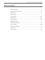
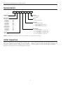
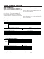
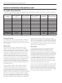
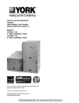
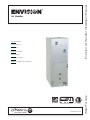
Envision Air Handler Installation Manual
Air Handler
Design Features
Factory Options
Accessories
Dimensional Data
Physical Data
Performance Data
IM1008HN 02/13
WaterFurnace
Engineering Guide Specifications
ENVISION AIR HANDLER INSTALLATION MANUAL
Table of Contents
Model Nomenclature. . . . . . . . . . . . . . . . . . . . . . . . . . . . . . . . . . . . . . . . . . . . . . . . . . . . . . . . . . . 4
General Installation Information . . . . . . . . . . . . . . . . . . . . . . . . . . . . . . . . . . . . . . . . . . . . . . . 5-11
Physical Data . . . . . . . . . . . . . . . . . . . . . . . . . . . . . . . . . . . . . . . . . . . . . . . . . . . . . . . . . . . . . . . . . 5
Sizing Selection . . . . . . . . . . . . . . . . . . . . . . . . . . . . . . . . . . . . . . . . . . . . . . . . . . . . . . . . . . . . . . . 6
Hydronic Models . . . . . . . . . . . . . . . . . . . . . . . . . . . . . . . . . . . . . . . . . . . . . . . . . . . . . . . . . . . 12-13
Electrical Data . . . . . . . . . . . . . . . . . . . . . . . . . . . . . . . . . . . . . . . . . . . . . . . . . . . . . . . . . . . . . 13-14
Wiring Schematics. . . . . . . . . . . . . . . . . . . . . . . . . . . . . . . . . . . . . . . . . . . . . . . . . . . . . . . . . . 15-16
ECM Blower Controls . . . . . . . . . . . . . . . . . . . . . . . . . . . . . . . . . . . . . . . . . . . . . . . . . . . . . . . . . . 17
Blower Performance Data . . . . . . . . . . . . . . . . . . . . . . . . . . . . . . . . . . . . . . . . . . . . . . . . . . . . . . 18
Dimensional Data . . . . . . . . . . . . . . . . . . . . . . . . . . . . . . . . . . . . . . . . . . . . . . . . . . . . . . . . . .19-20
Replacement Procedures . . . . . . . . . . . . . . . . . . . . . . . . . . . . . . . . . . . . . . . . . . . . . . . . . . . . . . 22
Service Parts. . . . . . . . . . . . . . . . . . . . . . . . . . . . . . . . . . . . . . . . . . . . . . . . . . . . . . . . . . . . . . . . . 22
Revision Guide . . . . . . . . . . . . . . . . . . . . . . . . . . . . . . . . . . . . . . . . . . . . . . . . . . . . . . . . . . . . . . . 23
ENVISION AIR HANDLER INSTALLATION MANUAL
Nomenclature
1-3
4-6
7
8-9
10
11
12
NAH
036
B
00
0
1
R
Model Type
NAH = Envision Series Air Handler
Air Coil
R = Refrigerant
H = Hydronic
Unit Capacity
Refrigerant Models Nom. CFM
022 MBTUH
800
026 MBTUH
925
030 MBTUH
980
036 MBTUH
1225
042 MBTUH
1425
048 MBTUH
1625
060 MBTUH
1760
Hydronic Models
026 MBTUH
925
036 MBTUH
1225
048 MBTUH
1625
060 MBTUH
1760
Motor
1 = ECM 208-230/60/1
Disconnect
0 = No breaker installed
(only on 5kW & 10kW heaters)
1 = Breaker installed
(only on 15kW & 20kW heaters)
Electric Heat
00 = No electric heat
05 = 5 kW (available on 022-036 only)
10 = 10 kW (available on 030-060 only)
15 = 15 kW (available on 042-060 only)
20 = 20 kW (available on 060 only)
Vintage
B = Current
NOTE: Kit NAHBC must be ordered to field convert the NAH042-060 to bottomflow air discharge.
Initial Inspection
Units in question should also be internally inspected. If any
damage is noted, the carrier should make the proper notation on the delivery receipt, acknowledging the damage.
When the equipment is received, all items should be carefully checked against the bill of lading to be sure all crates
and cartons have been received. Examine units for shipping
damage, removing the units from the packaging if necessary.
4
ENVISION AIR HANDLER INSTALLATION MANUAL
General Installation Information
tions in the literature, tags and labels attached to the unit
and other safety precautions that may apply.
Safety Considerations
Warning: Before performing service or maintenance operations on a system, turn off main power switches to the
equipment. Electrical shock could cause personal injury.
Follow all safety codes. Wear safety glasses and work
gloves. Use a quenching cloth for brazing operations and
have a fire extinguisher available.
Installing and servicing heating and air conditioning equipment can be hazardous due to system pressure and electrical components. Only trained and qualified service
personnel should install, repair or service heating and air
conditioning equipment. Untrained personnel can perform
the basic maintenance functions of cleaning coils and cleaning and replacing filters. All other operations should be
performed by trained service personnel. When working on
heating and air conditioning equipment, observe precau-
Note: Local codes and regulations take precedent over
any recommendations by the manufacturer. In addition to
conforming to manufacturer’s and local municipal building
codes, the equipment should also be installed in accordance
with the National Electric Code and National Fire Protection
Agency recommendations.
Physical Data
Air Handler Model Number (Refrigerant)
NAH022 NAH026 NAH030 NAH036 NAH042 NAH048 NAH060
Air Coil Total Face Area, ft2 [m2]
5.83 [0.54]
Tube outside diameter - in. [mm]
Evaporator
Coil
3/8 [9.52]
Number of rows
2
3
Fins per inch
12
Suction line connection - in. [mm] sweat
5/8 [15.87]
7/8 [22.22]
3/8 [9.52]
Liquid line connection - in. [mm] sweat
Refrigerant
R-410a
Nominal cooling capacity - tons [kW]
1.8 [6.44]
2.1 [7.59]
2.5 [8.79]
3 [10.55] 3.5 [12.30] 4 [14.06]
5 [17.58]
3/4 [19.05]
Condensate drain connection - (FPT) in. [mm]
Blower Wheel Size (Dia x W), in. [mm]
11 x 10 [279 x 254]
Blower motor type/speeds
Variable Speed ECM
1/2 [373]
Blower motor output - hp [W]
1 [746]
20 x 24 [508 x 635]
Filter Standard - 1" [51mm] MERV3 disposable, in. [mm]
208/230 - 1ph
Electrical characteristics (60hz)
215 [97.52]
195 [88.45]
Shipping weight - lbs. [kg]
Operating weight - lbs. [kg]
220 [99.79]
200 [90.71]
1/11/08
Air Handler Model Number (Hydronic)
Hydronic
Coil
NAH026 NAH036 NAH048 NAH060
Air Coil Total Face Area, ft2 [m2]
6.94 [0.64]
Tube outside diameter - in. [mm]
3/8 [9.52]
Number of rows
3
Fins per inch
13
7/8 [22.22]
7/8 [22.22]
Water In connection - in. [mm] sweat
Water Out connection - in. [mm] sweat
Nominal cooling capacity - tons [kW]
2.1 [7.59]
3 [10.55]
4 [14.06]
Blower Wheel Size (Dia x W), in. [mm]
11 x 10 [279 x 254]
Blower motor type/speeds
Variable Speed ECM
Blower motor output - hp [W]
5 [17.58]
3/4 [19.05]
Condensate drain connection - (FPT) in. [mm]
1/2 [373]
1 [746]
20 x 24 [508 x 635]
Filter Standard - 1" [51mm] MERV3 disposable, in. [mm]
208/230 - 1ph
Electrical characteristics (60hz)
220 [99.79]
200 [90.71]
Shipping weight - lbs. [kg]
Operating weight - lbs. [kg]
3/11/08
NOTE: Water connection dimensions are O.D.
5
ENVISION AIR HANDLER INSTALLATION MANUAL
General Installation Information cont.
Air Handler Sizing Selection
The Envision Air Handlers are designed for R410a refrigerant and should be matched with Envision Split series compressor
section according to the table below.
Air Handler
Indoor Split Model
(Single)
Indoor Split Model
(Dual Capacity)
NAH022B***1R
NSZ022
-
Outdoor Split Model
(Dual Capacity)
Airflow(CFM)
Electric Heat (kW)
800
5
NAH026B***1R
-
NDZ026
NDS026
925
5
NAH030B***1R
NSZ030
-
-
980
5, 10
NAH036B***1R
NSZ036
-
-
1225
5, 10
NAH036B***1R
-
NDZ038
NDS038
1225
5, 10
NAH042B***1R
NSZ042
-
-
1425
10, 15
NAH048B***1R
NSZ048
-
-
1625
10, 15
NAH048B***1R
-
NDZ049
NDS049
1625
10, 15
NAH060B***1R
NSZ060
-
-
1760
10, 15, 20
NAH060B***1R
-
NDZ064
NDS064
1760
10, 15, 20
NAH060B***1R
NSZ070
-
-
1760
10, 15, 20
NAH060B***1R
-
NDZ072
NDS072
1760
10, 15, 20
02/05/13
a finished living area to provide protection from water
damage in case of plugging of the air handler primary drain
line. The secondary drain line should terminate somewhere
that is easily visible by the homeowner. Be certain to show
the homeowner the termination location of the secondary
drain line and to explain its purpose.
Moving and Storage
If the equipment is not needed for immediate installation it
should be left in its shipping carton and stored in a clean,
dry area. Units must only be stored or moved in the normal
“up” orientation.
Unit Location
Duct System
Locate the unit in an indoor area that allows for easy
removal of the filter and access panels (the air handler
units are not approved for outdoor installation). Location
should have enough space for service personnel to perform
maintenance or repair. Provide sufficient room to make
refrigerant, electrical and duct connections. If the unit is
located in a confined space, such as a closet, provisions
must be made for return air to freely enter the space by
means of a louvered door, etc. The air handler section may
be installed on any level surface strong enough to support
its weight. When installed in a closet or on a stand, it
should be mounted on vibration absorbing material slightly
larger than the base to minimize vibration transmission to
the building structure.
The duct system should be sized to handle the design
airflow quietly and efficiently. To maximize sound
attenuation of the unit blower, the supply and return
plenums should include an internal duct liner of fiberglass or
constructed of ductboard for the first few feet. On systems
employing a metal duct system, canvas connectors should
be used between the unit and the ductwork. If air noise
or excessive airflow is a problem, the blower speed can
be changed. Application of the unit to un-insulated metal
ductwork in an unconditioned space will cause poor unit
performance and allow condensation to form on the duct
and possibly cause damage to the structure.
If the unit is connected to existing ductwork, check the duct
system to ensure that it has the capacity to accommodate
the air required for the unit application. If the duct is too
small, as in the replacement of heating only systems, larger
ductwork should be installed. All existing ductwork should
be checked for leaks and repaired as necessary.
When installed in an attic or above a drop ceiling, the
installation must conform to all local codes. If the unit
is suspended and installed in the horizontal position,
the entire length of the unit should be supported. If the
application requires the air handler to be installed on the
attic floor then the unit should be set in a full size secondary
drain pan. In this case the secondary drain pan should be
set on top of a vibration absorbing mesh. The secondary
drain pan is usually placed on a plywood base. A secondary
drain pan should be used when equipment is installed over
6
ENVISION AIR HANDLER INSTALLATION MANUAL
General Installation Information cont.
Condensate Drain
DS\bWT\SSRSR
!">D1
1]c^ZW\U
To facilitate condensate removal, the air handler should
be pitched 1/4” towards the drain in both directions. The
drain line contains cold water and should be insulated in
unconditioned spaces to avoid drain line condensation
from dripping on ceiling, etc. The drain pan has a primary
and auxiliary drain connection. The air handler drain
connections must be connected to a drain line and pitched
away from the unit a minimum of 1/8” per foot to allow
the condensate to flow away from the air handler. A trap
must be installed in the drain line below the bottom of the
drain pan to ensure free condensate flow (units are not
internally trapped). The primary condensate drain must
be terminated to an open drain or sump. Do not connect
the condensate drain to a closed waste system. An open
vertical air vent should be installed to overcome line length,
friction and static pressure. It is recommended that the
auxiliary drain be connected to a drain line for all units.
The auxiliary drain should be run to an area where the
homeowner will notice it draining. The drain line should not
be smaller than the drain connection at the condensate pan.
If the air handler is located in an unconditioned space, water
in the trap may freeze. It is recommended that the trap
material be of a type that will allow for expansion of water
when it freezes. Drain lines must be in conformance with
!">D1
!
&^S`T]]b
#
local codes.
Air Handler Configuration
The Envision Air Handler is factory configured for upflow
and horizontal left hand air discharge installation (Figure 1).
For bottomflow or horizontal right hand discharge, certain
field modifications are required.
Warning: Do not lift or reposition the ‘A’ coil by grasping
the copper tube header or distributor. This could cause a
tubing fracture resulting in a refrigerant leak.
Figure 1 - Factory configuration is top discharge and
horizontal left hand air discharge.
7
ENVISION AIR HANDLER INSTALLATION MANUAL
General Installation Information cont.
Bottomflow Application
Horizontal Right Air Discharge
Application
To convert the NAH series air handlers for bottomflow applications follow the steps shown below:
1. Remove all access panels. Disconnect the blower
harnesses from the motor and loosen ground wire from
blower. Remove the blower by removing 2 screws from
the blower mounting bracket, and slide the blower
assembly out the front. Remove the stiffener bracket in
front of coil, 'A' coil/pan assembly and the horizontal
drain pan. This will lighten the cabinet and make it easier
to maneuver.
2. Rotate the cabinet 180° from the upright position so that
the discharge air opening is located at the bottom and
the return air opening is at the top.
3. Install the blower assembly into the blower discharge
opening at the bottom of the cabinet by sliding the
blower mounting bracket under the discharge support
bracket and secure in place with 2 screws. The blower
harness and motor ground wire should be reattached
before sliding the blower into place.
4. On the NAH042-060 install the NAHBC bottomflow
conversion kit per instructions in the kit. Failure to install
this kit will result in condensate blow-off from the 'A'
coil into the cabinet and ductwork.
5. Install the 'A' coil into the upper section of the cabinet
as pictured in Figure 2. Attach the stiffener bracket into
the two holes provided in the cabinet so that the bracket
is in front of the coil. The horizontal drain pan is not
needed and must be discarded. Plug the 2 drain hole
openings in the access panel with the plugs provided.
6. Replace the access panels.
7. Bottom air discharge units require the supply air opening
to be cut at least a 1/2” larger than the unit’s air outlet.
8. When installed on combustible flooring, protect the
edges of the floor opening with sheet metal over wrap or
other non-combustible material.
9. Bottom air discharge units should be sealed well to the
floor to prevent air leakage.
To convert the NAH series air handlers for horizontal right
air discharge applications follow the steps shown below
1. Remove all access panels. Remove the stiffener bracket
in front of the coil, ‘A’ coil assembly and the horizontal
drain pan.
2. From the vertical upflow position, rotate the top of the
cabinet 90° to the right and set in place.
3. Remove the support bracket mounted to the top plate of
the ‘A’ coil. Rotate the ‘A’ coil support bracket 180° from
its original position and re-attach into existing holes in
the top plate of the coil. This must be done to prevent
the ‘A’ coil from falling into the drain pan (Figure 3).
4. Move the horizontal drain pan from the left side of the ‘A’
coil to the right hand side of the ‘A’ coil. Place the ‘A’ coil
and horizontal drain pan assembly into the cabinet
so that the support bracket is resting in the horizontal
drain pan as shown in Figure 3. Attach the stiffener
bracket into the two holes provided in the cabinet so that
the bracket is in front of the coil.
5. Remove the 2 drain plugs from the upper right of the
access panel and install them on the lower left of the
access panel. Replace the access panels.
6. If the unit is suspended, the entire length of the cabinet
should be supported.
Figure 3 - Horizontal Right Hand Air Discharge
Figure 2 - Bottomflow NAH.
Rotate the coil support bracket to this position
Important: When removing the coil, there is possible danger of equipment damage and personal injury. Be careful
when removing the coil assembly from the unit.
8
ENVISION AIR HANDLER INSTALLATION MANUAL
General Installation Information cont.
Refer to the Refrigerant Line Sizing table to determine the
proper line set configuration for the system being installed.
Line sets over 60 feet in length are not recommended. If
the line set is kinked or deformed and cannot be reformed,
Air Handler Installation
The air handler is attached to the shipping pallet with
screws. Prior to setting the unit in place remove the shipping screws located in the front base right behind the air
filter access panel. Also remove the external shipping brackets at the rear of the cabinet.
An air filter must always be installed upstream of the air
coil on the return air side of the air handler. An air filter is
provided with the air handler. If there is limited access to
the filter rack for normal maintenance, it is suggested that
a return air filter grille be installed. In this instance the filter
supplied with the air handler should be removed. Be sure
that the return duct is properly installed and free of leaks to
prevent dirt and debris from bypassing the filter and plugging the air coil.
The cabinet should be sealed so that unconditioned warm
air can not enter the cabinet. Warm air will introduce moisture into the cabinet which could result in water blow-off
problems, especially when installed in an unconditioned
space. Make sure that the liquid line, suction line and drain
line entry points into the cabinet are well sealed. Use the
butyl tape supplied with the air handler to seal around the
copper lines entering the cabinet.
the bad section of pipe should be replaced. A restricted
line set will affect unit performance. Line sets should be
routed as directly as possible, avoiding any unnecessary
bends and turns.
Important Note:
The bulb will need to be attached to the suction line on the
outside of the cabinet once the refrigerant line connections
have been made.
All wall penetrations should be sealed properly. The line
set should not come into direct contact with water pipes,
floor joists, wall studs, duct work, floors, walls and brick.
The line set should not be suspended from joists or studs
with a rigid wire or strap which comes into direct contact
with the tubing. Wide hanger straps which conform to the
shape of the tubing are recommended. All line sets should
be insulated with a minimum of 3/8” closed cell insulation. The line set insulation should be pliable, and should
completely surround the refrigerant line. As in all R-410a
equipment, a reversible liquid line filter drier is required to
insure all moisture is removed from the system. This drier
is factory installed in the Envision Split series compressor
section. This drier should be replaced whenever “breaking
into” the system for service. All exterior insulation should
be painted with UV resistant paint or covering to insure
long insulation life.
Leak Testing
The refrigeration line set must be pressurized and checked
for leaks before purging and charging the unit. To pressurize the line set, attach refrigerant gauges to the service
ports and add an inert gas (nitrogen or dry carbon dioxide)
until pressure reaches 60 to 90 PSIG. Never use oxygen or
acetylene to pressure test the system. Use an electronic
leak detector or a good quality bubble solution to detect
leaks on all connections made in the field. Be sure to check
the service valve ports and stems for leaks. If a leak is
found, repair it and repeat the above steps. For safety reasons do not pressurize the system above 150 PSIG. Purge
pressure from the line set slowly when the pressure test is
complete. The system is now ready for evacuation.
System Evacuation
Ensure that the line set and air coil are evacuated before
opening service valves. The line set and air coil must be
evacuated to 250 microns with a good quality vacuum
pump and use a vacuum gauge to ensure that air and
moisture are removed. With the system shut off from the
vacuum pump a sufficient system vacuum is achieved when
a 500 micron vacuum can be held for 30 minutes. A fast
rise to atmospheric pressure indicates a leak, while a slower
rise to around 1500 microns indicates moisture is still present in the system and further evacuation is required.
Connection to the Coil
Connect the refrigerant line set to the ‘A’ coil tubes. Nitrogen should be bled through the system at 2 to 3 PSI to prevent oxidation inside the refrigerant tubing. Use a low silver
phos-copper braze alloy on all brazed connections. The air
handler txv bulb is secured to the ‘A’ coil for shipping. The
Envision Split series compressor section is shipped with a
factory charge and the service valves are not to be opened
until the line set and air handler have been leak tested,
purged and evacuated. A damp towel or heat sink should
be used on the service valves to prevent damage caused by
excessive heat.
9
ENVISION AIR HANDLER INSTALLATION MANUAL
General Installation Information cont.
30 minutes after the adjustment is made for the system
to stabilize.
3. Once the proper superheat setting has been achieved
replace and tighten the seal cap.
Warning – There are 8 total (360°) turns on the superheat
adjustment stem from wide open to fully closed. When
adjusting the superheat stem counterclockwise (superheat
increase) and the stop is reached, any further counterclockwise turning adjustment will damage the valve.
Refrigeration
The Envision NAH series air handlers are supplied with an
expansion device. Once the line set has been brazed into
the air handler the txv bulb must be attached to the suction line outside of the cabinet and insulated with foam
tape. Be careful not to crush the txv bulb by over-tightening the clamp. The txv supplied has an internal check valve
so no external check valve is necessary. The air handler txv
should be adjusted initially per TXV Superheat Adjustments
table. Check sub-cooling and superheat, refrigerant charge
and txv may require further adjustment.
NOTE: The air handler is factory supplied with a holding
charge of dry nitrogen.
TXV Superheat Adjustment Procedure (see figure 4)
Txv’s may require adjustment for a specific application.
1. Remove the seal cap from the bottom of the valve.
2. Turn the adjustment screw counterclockwise to increase
superheat and clockwise to decrease superheat.
One complete 360° turn changes the superheat
approximately 3-4°F. You may need to allow as much as
Charging the System
Refer to IM1592 for charging the system, checking sub-cooling/superheat and unit operating parameters. Refer to the
Refrigerant Line Sizing table for initial refrigerant charge
amounts used with the Envision Split.
TXV Superheat Adjustments
E47>O`b
<c[PS`
!!>$'
!!>$'!
!!>$'#
!!>$'$
</6 </6 $
</6!
TOQb]`gaSb
</6!$
</6"
</6"&
</6$
TOQb]`gaSb
<]bS(EVS\W\abOZZW\UbVSaSOW`VO\RZS`aT]ZZ]ebVSbOPZS
T]`W\WbWOZbfdaSbbW\U
TOQb]`gaSb ]^S\ bc`\a
]^S\ bc`\a
1VSQYacPQ]]ZW\UO\Rac^S`VSObb]dS`WTgTW\OZaSbbW\U
Refrigerant Line Sizing
C\Wb
AWhS
TSSb
"TSSb
$TSSb
7\WbWOZ
<H4OQb]`g
AgabS[
1VO`US]h 1VO`US]h
/W`
6O\RZS`
AcQbW]\
:W_cWR
AcQbW]\
:W_cWR
AcQbW]\
:W_cWR
<AH
</6
#&=2
!&=2
#&=2
!&=2
!"=2
!&=2
#$
&&
<AH!
</6!
#&=2
!&=2
!"=2
!&=2
!"=2
!&=2
#$
&&
<AH!$
</6!$
#&=2
!&=2
!"=2
!&=2
!"=2
=2
#$
'$
<AH"
</6"
!"=2
!&=2
!"=2
!&=2
%&=2
=2
%"
'
<AH"&
</6"&
!"=2
!&=2
%&=2
!&=2
%&=2
=2
'
#
<AH$
</6$
%&=2
=2
%&=2
=2
&=2
=2
'
!
<AH%
</6$
%&=2
=2
%&=2
=2
&=2
=2
&
#
<2H $
</6 $
#&=2
!&=2
!"=2
!&=2
!"=2
=2
#
&"
<2H!&
</6!$
#&=2
!&=2
!"=2
!&=2
!"=2
=2
#$
'$
<2H"'
</6"&
!"=2
!&=2
%&=2
!&=2
%&=2
=2
'
#
<2H$"
</6$
%&=2
=2
%&=2
=2
&=2
=2
'
!
<2H%
</6$
%&=2
=2
%&=2
=2
&=2
=2
"
<]bSa(7\WbWOZAgabS[1VO`USW\QZcRSa4OQb]`gA^ZWbQVO`US ZW\SaSbQVO`US`S_cW`SRORRWbW]\OZQVO`US
bVS\ORXcabQVO`USPgacPQ]]ZW\UO\Rac^S`VSOb[SOac`S[S\ba
7TZW\SaSbWaZ]\US`bVO\ bVS\ORRWbW]\OZQVO`UST]`@"/Wa#]h^S`TbT]`!&O\R]h^S`TbT]` bcPS
10
#
@Sd($!%
ENVISION AIR HANDLER INSTALLATION MANUAL
General Installation Information cont.
Figure 4:
Decrease Superheat: Open Valve
Increase Superheat: Close Valve
11
ENVISION AIR HANDLER INSTALLATION MANUAL
Hydronic Models
The water heater and hydronic air handler must be located indoors and not subject to freezing temperatures.
The water heater must be installed in accordance to local
codes and its own installation instructions. The piping
between the water heater and air handler should be kept
to a minimum. Piping should be sized to allow for water
velocities of 2’-4’ per second. At average water velocities,
air bubbles should be carried along the piping to an air
separator where they can be discharged from the system.
Water velocities greater than 4’ per second could cause
flow noise and should be avoided. If water lines pass
through an unconditioned space they should be protected
to prevent them from freezing. Valves should be installed
to allow system isolation. All closed loop hydronic systems
must be equipped with an expansion tank to allow room for
the heated liquid to expand. A system is considered closed
when a check valve or backflow prevention valve is installed
in the cold water pipe upstream of the water heater.
Once piping is complete all air must be purged from the water lines. There is a dole valve at the top of the hydronic coil
header that can be opened to purge air from the coil. There
is also a plug at the bottom of the hydronic coil header for
draining the coil.
Dole valve for air purging
Plug for coil drainage.
Typical Installation. See the Hydronic Application Guide for other applications
!>A7
@3:734D/:D3
>`Saac`S
5OcUS
0OQY4Z]e>`SdS\bS`
>`Saac`S@SZWSTDOZdS
/W`
DS\b
:=/2>C;>
/W`
AS^O`Ob]`
3f^O\aW]\
BO\Y
2WSZSQb`WQ
C\W]\a
>B>]`ba
53=
AB=@/53
B/<9
EObS`4c`\OQS
6G2@=<71/7@6/<2:3@
B=
2A6
4@=;
2A6
A]c`QS7<
2WSZSQb`WQ
C\W]\a
Þ
4>B
>B>]`ba
>B>]`ba
A]c`QS=CB
0OZZDOZdS
<=B3(/!>A7^`Saac`S`SZWSTdOZdS
>O`b<](A@D!aV]cZRPScaSRW\
VgR`]\WQO^^ZWQObW]\a
EObS`4c`\OQS
6G2@=<71C<7B
12
ENVISION AIR HANDLER INSTALLATION MANUAL
Hydronic Models cont.
Water Presure Drop - Hydronic Coil
Flow gpm
Pressure Drop (PSI)
40°F
50°F
60°F
100°F
110°F
120°F
130°F
3.0
0.5
0.5
0.5
0.4
0.4
0.4
0.4
4.5
0.9
0.9
0.9
0.8
0.8
0.8
0.8
6.0
1.4
1.4
1.4
1.2
1.2
1.2
1.2
9.0
2.8
2.6
2.5
2.4
2.4
2.4
2.3
12.0
4.6
4.4
4.2
4.0
4.0
4.0
3.9
15.0
7.0
6.8
6.6
6.0
6.0
5.9
5.8
Coil Capacity vs. Entering Water Temperature
Entering Water Temperature °F
EAT °F
100
110
120
130
140
150
65
44%
56%
69%
81%
94%
106%
70
37%
50%
63%
75%
87%
100%
Electrical Data
All field wiring must comply with local and national fire,
safety and electrical codes. Be sure the available power is
the same voltage and phase as that shown on the unit serial
plate. Refer to the unit Electrical Data table for fuse and circuit breaker sizing. The thermostat should be connected to
the air handler and to the compressor section. Line voltage
power should be supplied to the breakers on air handlers
with 15kW and 20kW heater kits (see the electric heat
control section picture). On air handlers with no electric
heat installed, or with 5kW and 10kW heater kits the power
should be supplied to L1 and L2 lugs on PB (see air handler
control section picture).
Air Handler Control Section:
Power should be supplied to PB on air handlers with no
electric heat and 5kW or 10kW heaters.
Electric Heat Control Section:
Power should be supplied to the breakers on air handlers
with 15kW and 20kW heaters.
13
ENVISION AIR HANDLER INSTALLATION MANUAL
Electrical Data cont.
Model
022
026
030
036
042
048
060
Electric Heat
Capacity
KW
240v
BTUH
240v
0
4.8
0
4.8
0
4.8
9.6
0
4.8
9.6
0
9.6
14.4
0
16,382
0
16,382
0
16,382
32,765
0
16,382
32,765
0
32,765
49,147
14.4
49,147
0
9.6
14.4
0
32,765
49,147
14.4
49,147
0
9.6
14.4
0
32,765
49,147
14.4
49,147
19.2
65,530
19.2
65,530
Supply
Circuit
single
single
single
single
single
single
single
single
L1/L2
L3/L4
single
single
L1/L2
L3/L4
single
single
L1/L2
L3/L4
single
L1/L2
L3/L4
Aux. Heat
Minimum
CFM
Rated Voltage
Voltage
Min/Max
Blower
Motor FLA
197/253
4.0
4.0
4.0
4.0
4.0
4.0
4.0
4.0
4.0
4.0
7.0
7.0
7.0
7.0
7.0
7.0
7.0
7.0
7.0
7.0
7.0
7.0
7.0
7.0
-
740
740
740
900
740
900
900
1,275
208-230/60/1
900
1,275
900
1,275
1,700
Heater
Ampacity
Total Unit FLA
Minimum Circuit
Ampacity
Maximum Fuse/
HACR
208v
240v
208v
240v
208v
240v
208v
240v
17.3
17.3
17.3
34.7
17.3
34.7
34.7
52.0
34.7
17.3
34.7
52.0
34.7
17.3
34.7
52.0
34.7
17.3
69.3
34.7
34.7
20.0
20.0
20.0
40.0
20.0
40.0
40.0
60.0
40.0
20.0
40.0
60.0
40.0
20.0
40.0
60.0
40.0
20.0
80.0
40.0
40.0
4.0
21.3
4.0
21.3
4.0
21.3
38.7
4.0
21.3
38.7
7.0
41.7
59.0
41.7
17.3
7.0
41.7
59.0
41.7
17.3
7.0
41.7
59.0
41.7
17.3
76.3
41.7
34.7
4.0
24.0
4.0
24.0
4.0
24.0
44.0
4.0
24.0
44.0
7.0
47.0
67.0
47.0
20.0
7.0
47.0
67.0
47.0
20.0
7.0
47.0
67.0
47.0
20.0
87.0
47.0
40.0
5.0
26.6
5.0
26.6
5.0
26.6
48.4
5.0
26.6
48.4
8.8
52.1
73.8
52.1
21.6
8.8
52.1
73.8
52.1
21.6
8.8
52.1
73.8
52.1
21.6
95.4
52.1
43.4
5.0
30.0
5.0
30.0
5.0
30.0
55.0
5.0
30.0
55.0
8.8
58.8
83.8
58.8
25.0
8.8
58.8
83.8
58.8
25.0
8.8
58.8
83.8
58.8
25.0
108.8
58.8
50.0
10
30
10
30
10
30
50
10
30
50
15
60
80
60
25
15
60
80
60
25
15
60
80
60
25
100
60
50
10
30
10
30
10
30
60
10
30
60
15
60
90
60
25
15
60
90
60
25
15
60
90
60
25
110
60
50
7/11/08
Rated Voltage of 208/230/60/1
HACR circuit breaker in USA only
Low Voltage Point to Point Wiring
To Air
Handler
C
R
G
O
Y1
Y2
W
From
Thermostat
C
R
G
O
Y1
Y2
W2
L
To Compressor
Section
C
R
O
Y1
Y2
L
Air Handler transformer must be 75VA.
5/29/08
14
ENVISION AIR HANDLER INSTALLATION MANUAL
Wiring Schematics
208-230/60/1
G
Legend
PB
L1
Transformer
Factory Low voltage wiring
Factory Line voltage wiring
Field low voltage wiring
Field line voltage wiring
Optional block
DC Voltage PCB traces
Internal junction
Quick connect terminal
T
G
Thermistor
L2
Light emitting diode - Green
24V
Red
Gry(4)
Brown
Orange
NOTE 1
Blue
Relay coil
Grn
Capacitor w/ bleed resistor
Yel
Blk/Wh
Switch - Condensate overflow
P4
8
Wire nut
Switch - High pressure
Field wire lug
L1
Grn/Yel(1)
Switch -Hot Water On/Off
Fuse
HE ER1 to ER4 LP -
C
Grn(9)
Switch - Low pressure
Ground
Relay ContactsN.O., N.C.
P
Heater element
Aux heat stage relays
Low pressure switch
LED
XFRM
SEC
Note 3
R
1 2 3
Polarized connector
PB SW1 -
Power block
DIP package 10 position
Thermostat
C
R
R
208-230/60/1
G
ODD
PB
L1
L2
Red
SW1 On
1
Black
8
2
3
Black
1
Black
1
C1
16
Black
16
RPM
12
Black
12
R
5
Black
5
3
3
4
5
RPM grnd
Gray ER1
C2
Gry(12)
NO
COOL
7
Black
7
ADJUST
11
Black
11
HEAT
4
Black
4
DELAY
10
Black
10
BK
6
Black
6
Y1
14
Black
14
15
Black
15
On/Off
9
Black
9
O
NO
ECM
Blower
Motor
Thermostat
LED
1
Note 3
C
C
R
R
ODD
Y1
Y2
1
2
3
4
5
6
7
8
9
10
SW1 On
Y1
Y2
G
G
O
O/B
2
3
8
Black
8
RPM grnd
3
Black
3
C2
Black
1
C1
16
Black
16
RPM
12
Black
12
R
5
Black
5
COOL
7
Black
7
ADJUST
11
Black
11
HEAT
4
Black
4
DELAY
10
Black
10
BK
6
1
XFRM
SEC
P3
Y /Y2
NO
1
Y1
2
Black
2
W / W1
Y2
13
Black
13
EM / W2
G
G
O
O/B
W
W2
4
5
3
4
5
6
P2
W2
Wht(28)
Electric Heat
208-230/60/1
ECM
Blower
Motor
G
6
Black
14
Y /Y2
15
Black
15
On/Off
9
Black
9
O
2
Black
2
W / W1
13
Black
13
24V
Red
Gry(4)
Yel(5)
Brown
Orange
NOTE 1
Blue
Grn
Yel
Blk/Wh
1
P4
EM / W2
8
C
Grn/Yel(1)
W2
LED
XFRM
SEC
Note 3
R
W2
1
2
3
4
5
6
7
8
9
10
Air Handler No Electric Heat
Thermostat
C
R
P3
C
R
ODD
Notes:
1 – To operate in 208V mode replace the blue transformer
wire connected to PB-L2 with red transformer wire.
2 – Jumper wires tie stages (1) with (2) and (3) with (4).
3 – Dip switches are used to select the air flow.
Yel(7)
Gry(6)
L2
Black
Y1
Black
14
PB
L1
Transformer
Grn(9)
W1
2
Air Handler w/ 5kW Electric Heat
W1
W
ER4
Grn(9)
Blk/Wh
R
ER3
NO
Y2
W1
P4
Grn/Yel(1)
P1
NOTE 2
Grn
C
TS1
W1
Brown
Orange
NOTE 1
Blue
Yel
HE1
ER2
Y1
Black
24V
1
2
3
4
5
6
7
8
9
10
P3
C
Transformer
Gry(6)
Black
SW1 On
Black
8
2
3
3
Black
1
Black
1
C1
16
Black
16
RPM
12
Black
12
R
5
Black
5
7
Black
7
ADJUST
11
Black
11
HEAT
4
Black
4
DELAY
10
Black
10
BK
6
Black
6
Y1
14
Black
14
Y /Y2
15
Black
15
On/Off
9
Black
9
O
3
Y1
2
Black
2
W / W1
Y2
13
Black
13
EM / W2
G
O/B
Gray ER1
Gry(12)
NO
HE1
TS1
HE3
TS3
ER2
COOL
Y1
O
5
C2
Y2
G
4
RPM grnd
NO
ECM
Blower
Motor
P1
ER3
Yel(16)
NO
NOTE 2
ER4
NO
1
2
3
4
5
6
P2
Wht(10) Blu(11)
W1
W
W2
TDR
W1
W2
Wht(8)
Grn(9)
Air Handler w/ 10kW Electric Heat
15
Electric Heat
97P787-01
02/05/13
ENVISION AIR HANDLER INSTALLATION MANUAL
Wiring Schematics cont.
Legend
208-230/60/1
208-230/60/1
Circuit 1
Circuit 2
G
Factory Low voltage wiring
Factory Line voltage wiring
Field low voltage wiring
Field line voltage wiring
Optional block
DC Voltage PCB traces
Internal junction
Quick connect terminal
T
G
Thermistor
L1
L2
L3
Note 4
L4
G
PB
L1
Transformer
Light emitting diode - Green
Red (2)
L2
Black(3)
Black
Relay coil
24V
Capacitor w/ bleed resistor
Red
BRK2
BRK1
Brown
Orange
NOTE 1
Grn
Blue
Gry(20)
Blk(21)
Switch - Condensate overflow
Wire nut
Yel
Blk/Wh
Switch - High pressure
Yel(22)
Field wire lug
L1
Ground
Relay ContactsN.O., N.C.
HE ER1 to ER4 LP -
P
Heater element
Aux heat stage relays
Low pressure switch
1 2 3
PB SW1 -
Grn/Yel(1)
LED
XFRM
SEC
Polarized connector
Note 3
R
Power block
DIP package 10 position
Thermostat
1
2
3
4
5
6
7
8
9
10
P3
C
208-230/60/1
C
R
R
ODD
G
PB
L1
Transformer
L2
Black
24V
Red
Blue
Y1
Y1
Y2
Y2
G
G
O
O/B
W
W2
R
3
C2
1
C1
16
Black
16
RPM
12
Black
12
R
Blk(25)
Gray ER1
Gry(12)
NO
5
Black
7
Black
7
ADJUST
Black
11
HEAT
Black
4
DELAY
Black
10
BK
6
Black
6
Y1
14
Black
14
15
Black
15
On/Off
9
Black
9
O
2
Black
2
W / W1
13
Black
13
EM / W2
NO
ECM
Blower
Motor
1
XFRM
SEC
Note 3
1
2
3
4
5
6
7
8
9
10
P3
C
R
Black
2
3
8
RPM grnd
3
Black
3
C2
Black
1
C1
16
Black
16
RPM
12
Black
12
5
Black
5
COOL
7
Black
7
ADJUST
11
Black
11
HEAT
P1
Black
4
DELAY
Black
10
BK
6
Black
6
Y1
14
Black
14
15
Black
9
15
On/Off
Black
9
O
Y1
2
Black
2
W / W1
Y2
Y2
13
Black
13
EM / W2
G
G
O
O/B
W
W2
SW1 On
4
NO
HE3
TS3
ER4
Y /Y2
NO
1
W2
2
3
4
5
6
P2
Wht(8)
Electric Heat
Air Handler w/ 15kW Electric Heat
ECM
Blower
Motor
L1
Circuit 2
L1
L2
L3
L4
Note 4
G
24V
Red
Black(3)
Brown
Orange
NOTE 1
Grn
Blue
Yel
8
LED
XFRM
SEC
Note 3
R
1
2
3
4
5
6
7
8
9
10
Air Handler No Electric Heat
Thermostat
C
R
P3
C
R
ODD
Y1
Gry(20)
Blk(21)
Blk/Wh
C
W2
BRK2
BRK1
Red (2)
L2
Black
Grn/Yel(1)
Notes:
1 – To operate in 208V mode replace the blue transformer
wire connected to PB-L2 with red transformer wire.
2 – Jumper wires tie stages (1) with (2) and (3) with (4).
3 – Dip switches are used to select the air flow.
4 – For single circuit operation field supplied jumper wires
should be applied between L1 & L3 and L2 & L4.
Jumper wires must be sized to carry the single circuit
ampacity of the equipment.
208-230/60/1
Circuit 1
PB
Transformer
Grn(9)
W1
208-230/60/1
G
1
P4
W1
TS2
Yel(16)
5
Y /Y2
Y1
ODD
HE2
ER3
NOTE 2
R
10
4
TS1
Blk(14)
COOL
10
HE1
ER2
Yel(26)
11
5
Gry(24)
TDR
W1
1
8
LED
R
C
RPM grnd
Black
Black
5
Grn(9)
C
Thermostat
8
3
Blk/Wh
P4
Grn/Yel(1)
4
Wht(10) Blu(11)
Grn
Yel
3
1
4
SW1 On
2
W1
Brown
Orange
NOTE 1
Black
8
C
Grn(9)
Switch -Hot Water On/Off
Fuse
1
P4
Switch - Low pressure
Y1
Y2
Y2
G
G
O
O/B
W
W2
SW1 On
Black
2
3
4
8
RPM grnd
3
Black
3
C2
1
Black
1
C1
16
Black
16
RPM
12
Black
12
R
5
Black
5
COOL
5
Yel(22)
Pnk(23)
Gry(24)
Blk(25)
Gray ER1
Gry(12)
NO
Black
7
ADJUST
Black
11
HEAT
4
Black
4
DELAY
10
Black
10
BK
6
Black
6
Y1
ECM
Blower
Motor
TS1
Blk(14)
Pnk(27)
7
11
HE1
ER2
Yel(26)
NO
P1
HE2
TS2
HE3
TS3
HE4
TS4
ER3
Yel(16)
NO
NOTE 2
ER4
Pnk(18)
14
Black
14
15
Black
15
On/Off
9
Black
9
O
2
Black
2
W / W1
13
Black
13
EM / W2
Y /Y2
NO
1
2
3
4
5
6
P2
Wht(10) Blu(11)
W1
TDR
W1
W2
Wht(8)
Grn(9)
Air Handler w/ 20kW Electric Heat
16
Electric Heat
97P787-01
02/05/13
ENVISION AIR HANDLER INSTALLATION MANUAL
ECM Blower Control
The ECM blower motor is controlled by an interface board
installed in the air handler and allows field selectable CFM
settings. The interface board receives inputs from the
thermostat and converts them to signals used by the ECM
motor. There are four different airflow settings that are field
selectable via DIP switches (see Blower Performance table).
Cooling/Heating settings
The cooling/heating CFM settings determine the
normal cooling/heating CFM when the unit is not in
dehumidification mode or auxiliary heat mode. DIP switches
1 and 2 ‘off’ is the lowest CFM setting while with DIP
switches 1 and 2 ‘on’ is the highest CFM setting. To prevent
air coil freeze up, the lowest CFM setting can not be used
when dehumidification mode is selected. DIP 9 must be ‘on’
to enable normal airflow settings.
Dehumidification Mode settings
This setting provides for field selection of humidity control
(via setting DIP 9 ‘off’). The cooling airflow settings are
determined by the Cooling/Heating DIP switch settings
above. Dehumidification mode reduces the selected normal
cooling CFM by 15%-20% which increases the moisture
removing capability of the heat pump. To prevent air coil
freeze up, the lowest CFM setting can not be used when
dehumidification mode is selected.
Dehumidification Mode (Continuous) – This mode is
selected via setting DIP 9 ‘off’ on the ECM interface board
and will be engaged whenever an ‘O’ input is present. In this
mode any time the unit is operating in cooling mode, it will
run at a CFM level 15%-20% lower than the selected normal
cooling CFM.
NOTE: Do not select dehumidification mode if the lowest
Cooling/Heating airflow level is selected (DIPS 1 & 2 off).
Auxiliary Heat settings - DIP 5 and 6 on the ECM interface
board are used to select the desired CFM in auxiliary/
emergency heat mode. Whenever auxiliary or emergency
electric heat is energized this air flow setting will be used.
NOTE: DIP switches 3, 4, 7, 8, and 10 are not used.
17
ENVISION AIR HANDLER INSTALLATION MANUAL
Blower Performance
Blower Performance Variable Speed ECM
Model
Max
ESP
(wg)
Blower
Motor
(hp)
0.50
1/2
On
1/2
Off
0.50
HP CFM Setting
S1
S2
Normal Mode Htg & Clg
Stg 2
Stg 1
On
900
On
800
Dehumidification Mode Clg
Aux CFM Setting
S6
Aux
Emerg
Mode
On
On
1000
Off
On
800
Blower
S9
Stg 2
Stg 1
Blower
S5
700
450
Off
775
600
450
625
400
Off
680
530
400
Off
600
450
375
On
Off
775
Off
Off
740
022
0.50
1/2
On
Off
700
540
375
0.50
1/2
Off
Off
640
480
350
0.50
1/2
On
On
1050
800
525
Off
850
700
525
On
On
1150
0.50
1/2
Off
On
925
725
475
Off
760
620
475
Off
On
950
0.50
1/2
On
Off
800
625
425
Off
670
540
425
On
Off
925
0.50
1/2
Off
Off
740
575
400
Off
Off
825
0.50
1/2
On
On
1150
950
600
Off
975
775
600
On
On
1250
0.50
1/2
Off
On
980
780
500
Off
825
640
500
Off
On
1000
0.50
1/2
On
Off
900
700
440
Off
750
580
440
0.50
1/2
Off
Off
800
630
425
0.50
1/2
On
On
1300
1025
760
Off
1105
871
760
On
On
1300
0.50
1/2
Off
On
1225
950
685
Off
1041
808
685
Off
On
1250
0.50
1/2
On
Off
1150
850
620
Off
940
690
620
0.50
1/2
Off
Off
1075
800
550
0.75
1
On
On
1500
1100
750
Off
0.75
1
Off
On
1425
1010
650
Off
0.75
1
On
Off
1300
975
635
Off
0.75
1
Off
Off
1150
850
625
0.75
1
On
On
1700
1300
975
Off
0.75
1
Off
On
1625
1240
875
0.75
1
On
Off
1450
1100
750
0.75
1
Off
Off
1300
1000
675
0.75
1
On
On
1850
1750
1175
0.75
1
Off
On
1760
1625
0.75
1
On
Off
1720
1575
0.75
1
Off
Off
1680
1525
975
026
030
On
Off
975
Off
Off
900
036
1250
On
Off
1225
Off
Off
1200
On
1550
900
750
On
1180
840
650
Off
On
1450
1080
800
635
On
Off
1400
Off
Off
1275
1400
1080
975
On
On
1700
Off
1350
1025
875
Off
On
1550
Off
1200
900
750
On
Off
1525
Off
Off
1400
Off
1540
1450
1175
On
On
1850
1050
Off
1460
1350
1050
Off
On
1760
1015
Off
1425
1300
1015
On
Off
1725
Off
Off
1700
042
048
060
2/3/10
Factory CFM settings are in boldface
CFM is controlled within 5% up to maximum ESP
Maximum ESP includes allowance for wet coil and standard filter
DIP switch 9 must be 'OFF' to select dehumidification mode
Off
SW1
On
1
2
Heating and Cooling
3
4
5
6
Auxiliary Heating
7
8
9
1428
Dehumidification
10
18
ENVISION AIR HANDLER INSTALLATION MANUAL
Unit Start Up
•
•
•
•
•
•
•
•
•
•
•
•
•
•
•
Check that supply voltage matches nameplate data.
Fuses, breakers and wire size are correct.
Low voltage wiring is complete.
Piping is complete and water system is cleaned
and flushed.
Air is purged from the closed loop system.
Isolation valves are open, water control valves or pumps
are wired.
Condensate line is open and correctly pitched.
Transformer switched to 208v if applicable.
DIP switches are set correctly.
Blower rotates freely.
Blower speed is correct.
Air filter/cleaner is clean and in position.
Service/access panels are in place.
Return air temperature is between 50-80°F heating and
60-95° cooling.
Check air coil cleanliness to insure optimum performance.
Clean as needed according to maintenance guidelines.
To obtain maximum performance the air coil should be
cleaned before startup. A 10 percent solution of
dishwasher detergent and water is recommended for
both sides of coil. A thorough water rinse should follow.
Maintenance Filters
Filters must be clean to obtain maximum performance.
They should be inspected monthly under normal operating
conditions and be replaced when necessary. Units should
never be operated without a filter. Always replace the filter
with the same type as originally furnished.
Condensate Drain
In areas where airborne bacteria produce slime in the drain
pan, it may be necessary to treat chemically to minimize the
problem. The condensate drain can pick up lint and dirt,
especially with dirty filters.
Blower Motors
The ECM motor is equipped with sealed ball bearings and
requires no periodic lubrication.
Air Coil
The air coil must be cleaned to obtain maximum performance. Check once a year under normal operating conditions and, if dirty, brush or vacuum clean. Care must be
taken not to damage the aluminum fins while cleaning.
Caution: Fin edges are sharp.
19
ENVISION AIR HANDLER INSTALLATION MANUAL
Dimensional Data
Top Flow/Horizontal Unit Configuration
B=>D73E
4@=<BD73E
DD
@756BA723D73E
CC
EE
FF
G
GG
D
C
II
HH
E
0=BB=;D73E
J
K
L
M
AA
BB
O
F
N
P
B
Q
JJ
H
R
I
S
T
U
V
LL
Topflow/
Horizontal
Configuration
Refrigerant/Water
Connections
Overall Cabinet
A
B
C
Width Depth Height
026-060
A
MM
D
E
F
3/4" cond
1/2" cond
Return
Power
Supply
Low
Voltage
Air Duct
Flange
G
H
I
J
K
L
Suction /
Water Out
M
Liquid /
Water In
N
O
P
Q
R
S
in.
21.0
26.1
57.3
54.0
52.3
0.7
58.1
27.4
28.3
26.4
23.9
15.9
9.5
3.8
3.2
0.9
1.5
10.5
15.5
cm.
53.4
66.3
145.6
137.2
132.7
1.8
147.4
69.6
71.8
67.2
60.8
40.4
24.0
9.6
8.1
2.4
3.9
26.7
39.4
S
T
JJ
KK
LL
MM
U
V
W
X
Y
Z
AA
BB
CC
DD
EE
FF
GG
HH
1" cond
Power
Supply
II
1/2" cond
Low
Voltage
15.5
18.0
19.5
20.1
59.5
15.1
53.1
51.3
7.4
4.9
1.5
18.0
1.5
18.0
2.0
2.0
2.0
22.1
2.0
16.9
1.96
39.4
45.8
49.5
51.0
151.1
38.4
134.9 130.2
18.9
12.5
3.8
45.7
3.8
45.7
5.1
5.1
5.1
56.2
5.0
42.9
5.0
Condensate is stainless steel 3/4" FPT
Discharge flange is field installed and extends 1" (25.4 mm) from cabinet
20
Rev:A 3/12/08
ENVISION AIR HANDLER INSTALLATION MANUAL
Dimensional Data cont.
Bottom Flow Unit Configuration
B=>D73E
4@=<BD73E
@756BA723D73E
I
A
B
X
W
V
0.71 F
U
JJ
T
S
R
H
KK
LL
MM
Y
G
C
0=BB=;D73E
CC
DD
EE
J
K
L
D
M
AA
N
BB
FF
E
O
P
HH
GG
II
Q
Z
Refrigerant/Water
Connections
Overall Cabinet
Bottomflow
Configuration
A
Width
026-060
B
C
Depth Height
D
E
F
3/4" cond
1" cond
Return
Low
Voltage
Power
Supply
Air Duct
Flange
G
H
I
J
K
L
M
Suction /
Water Out
Liquid /
Water In
N
O
P
Q
R
in.
21.0
26.1
57.3
5.1
3.3
0.7
58.1
27.4
28.3
51.6
49.1
41.2
34.6
29.2
28.6
6.1
4.2
0.9
cm.
53.4
66.3
145.6
12.9
8.5
1.8
147.4
69.6
71.8
131.1 124.7
104.7
87.9
74.2
72.7
15.4
10.8
2.4
AA
BB
1" cond
1/2" cond
II
JJ
KK
LL
MM
Power
Supply
Low Voltage
CC
S
T
U
V
W
X
Y
Z
DD
EE
FF
GG HH
1.5
10.5
15.5
18.0
19.5
20.1
59.1
15.1
32.6
30.1
2.0
2.0
2.0
18.0
1.5
18.0
1.5
22.1
2.0
16.9
1.96
3.9
26.7
39.4
45.8
49.5
51.0
150.0
38.4
82.8
76.5
5.1
5.1
5.1
45.7
3.8
45.7
3.8
56.2
5.0
42.9
5.0
Condensate is stainless steel 3/4" FPT
Discharge flange is field installed and extends 1" (25.4 mm) from cabinet
21
Rev:A 3/12/08
ENVISION AIR HANDLER INSTALLATION MANUAL
Replacement Procedures
Obtaining Parts
When ordering service or replacement parts, refer to the
model number and serial number of the unit as stamped on
the serial plate attached to the unit. If replacement parts are
required, mention the date of installation of the unit and the
date of failure, along with an explanation of the malfunctions
and a description of the replacement parts required.
In Warranty Material Return
Material may not be returned except by permission of authorized warranty personnel. Contact your local distributor
for warranty return authorization and assistance.
Service Parts
DX Refrigerant Models
Hydronic Models
Part Description
Refrigeration
022****R
Air Coil
ECM Motor & Blower
Electrical
Filter
030****R
33P609-01
042****R
54S555-01
048****R
060****R
026****H
61S551-02
33P609-03
33P609-05
54S555-02 54S555-03 54S555-04 54S556-01
ECM Blower Housing
ECM Motor
208-230/60/1
036****R
61S552-02
TXV
Blower Assembly
026****R
14S555-02
14S555-03
14S555-04
048****H
33P609-06
54S556-02 54S556-03
N/A
54S555-01
54S555-02 54S556-02 54S556-03
53P501B01
14S556-01
14S556-02
14S556-03
14S555-02
14S555-04
14S556-02
ECM Power Harness
11P585B01
11P585B01
ECM Control Harness
11P598-01
11P598-01
Control board
17P551-01
17P551-01
Transformer
15P501B01
15P501B01
Power Block
12P501A02
12P501A02
Ground Lug
12P004A
12P004A
59P020B14
59P020B14
Air Filter
20” x 24” x 1”
060****H
61S553-02
53P501B01
14S555-01
036****H
14S556-03
2/1/2013
22
ENVISION AIR HANDLER INSTALLATION MANUAL
Revision Guide
Pages:
All
Description:
Updated Nomenclature For New ECM Motor
Date:
By:
20 Feb 2013
DS
22
Added Service Parts List
20 Feb 2013
DS
23
Added Revision Guide
20 Feb 2013
DS
23
Manufactured by
WaterFurnace International, Inc.
9000 Conservation Way
Fort Wayne, IN 46809
www.waterfurnace.com
IM1008HN
02/13
Product:
Type:
Size:
Document:
Envision Series - Air Handler
Hydronic or R-410A
2-6 Tons
Installation Manual
©2013 WaterFurnace International, Inc., 9000 Conservation Way, Fort Wayne, IN 46809-9794. WaterFurnace has a policy of continual product research and development and
reserves the right to change design and specifications without notice. ©2009 WaterFurnace International, Inc.