1
USB Overview
This course serves as an introduction to USB.
1
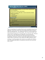
Agenda
USB overview
USB low level data transfer
USB protocol structure
USB chapter 9 structure
Enumeration
Standard classes
Firmware example
Silicon Labs solutions
Where to get more information
2
We are going to cover fairly in depth overview of USB, the device families that
support USB connectivity, and some of the tools available to the support customer
designs. At then end we will illustrate how Silicon Labs supports USB efforts and
can abstract all of what you are about to learn.
2
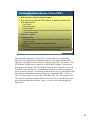
Advantages of USB
Ease of Use
One interface for many devices
Hot pluggable
Automatic configuration
No power supply required
Devices can pull up to 500 mA from the bus
Reliability
Lossless data transfers
Type A/B
Mini
Speed
Three transfer speeds
Low Speed – 1.5 Mbps (USB 1.1 and 2.0)
Full Speed – 12 Mbps (USB 1.1 and 2.0)
Hi-Speed – 480 Mbps (USB 2.0 only)
Low Power Consumption
Suspend mode
Devices consume 500 uA or less (USB 2.0)
Devices consume 2.5 mA or less (USB 3.0)
Availability
Micro
Microsoft and Intel’s PC 2001 System Design
Guide requires that all new PC’s have two useraccessible USB ports
3
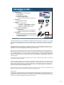
USB is proliferating due to the fact that RS232 is disappearing and that the end user’s experience is very simple.
Everything is strictly specified. The USB cable and connector have been defined by the USB consortium all the
way down to the USB symbol dimensions. This provides confidence that any device will connect to another
device.
Hot pluggable/Automatic configuration – Enumeration (which we will get into detail later) enables a device to
be plugged in and its operating parameters communicated to the host. Also, the USB spec takes into account
inrush currents for devices that are going to draw their power from the bus.
When we refer to lossless data transfers we are referring to the fact that the protocol provides a mechanism to
retransmit data if required in all but one transfer type. This enables the data transfers to be reliable and we will
go over that later in the course. There are three transfer speeds for USB 2.0. The transfer speed number listed
here is the bandwidth on the bus. This is not directly equal to data throughput. The throughput is less than these
numbers for any USB device due to USB overhead. Later in the presentation we will show some numbers for
actual throughput.
The USB 2.0 protocol is fully backwards compliant. This is why the C8051F32x and 34x devices are full speed
devices and also USB 2.0 compliant.
The 500 uA listed here applies to devices that are consuming power from the USB host. If a device is fully selfpowered, the Suspend mode current is not applicable because it is not drawing power from the USB host. Note
that the USB 3.0 specification allows for 2.5mA suspend current. Another aspect of the newer specification is
that the micro connectors are now the preferred connector solution. The USB implementers forum deprecated
the use of the mini-A and mini-AB (May 23, 2007).
The benefit of this aspect of the System Design Guide means that user’s don’t need to buy external hardware and
developers know that USB is an interface their customers will definitely have.
USB3.0 Notes:
Existing USB root hubs and external hubs in the field (and still manufactured by most companies) that are USB
2.0 compliant based on the pre-ECN spec will still enforce the 500 uA limitation. Only newly certified hubs
would need to comply with the post-ECN spec. In summary, it is best to make your product obey the stricter rule
of 500 uA for the widest compatibility with existing PCs and hubs.
3
Some USB Terms
Host — computer that controls the interface
Function — device that provides a capability to the host
Hub — device with one or more connections to USB devices plus hardware to enable
communications with each device
Device — something that attaches to a USB port (sometimes synonymous with a function)
Port — a connector on the USB Host bus
Suspend — Device enters Suspend after 3mS of inactivity on the bus to minimize power
consumption. Host uses timing packet to keep Peripherals active.
Enumeration — Initialization sequence to inform the host what device was attached to the
bus. Device parameters are conveyed at this point.
Descriptors — List of tables that identify the capabilities of the device
Endpoint — All transmissions travel to/from and endpoint which is just a block of memory or a
register. Endpoint 0 is the control endpoint which is the only bi-directional endpoint typically
used for enumeration.
Descriptors — List of tables that identify the capabilities of the device
USB Ports
4
Here are some common terms when discussing USB. Take a moment to familiarize
yourself with these terms.
4
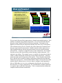
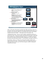
What is USB?
Serial protocol—strictly defined frame and
packet based protocol with error checking and
handshaking. LSB in first, MSB last.
Host Controller
Root Hub
Half Duplex—all transactions initiated by the
host with data carried by the D+ and D- signals
in both directions
Device Management—host assigns addresses
to newly attached devices and removes support
for detached devices. Host also manages
bandwidth.
Peripheral
Hub
Power Management—use of Suspend mode
to conserve power on the bus. Vbus sourced
by host is +5V ±5%.
Peripheral
Hub
Peripheral
Peripheral
Direction—all transactions are directed with
respect to the host. IN transactions send data
from the peripheral to the host. OUT
transactions send data from the host to the
peripheral.
5
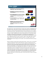
The USB protocol is a packet based architecture with start frame, transactions, and handshaking with
ack and nak controls. These will be covered later. Within the host there is the USB controller and
the root hub. The Host controller formats the data for the OS on read and write as well as manages
communications on the bus. The Root Hub provides the connection point to the host for peripheral
devices as well as detects attach/removal events, carries out requests from the host and is the means
to pass data. USB is a half duplex protocol where all data is passed via a two wire interface called
D+ (D plus) and D- (D minus). The host processor is responsible for all communications on the bus
including device addressing and bus bandwidth. It is also responsible for determining and
conserving the power requirements for the bus. If devices do not meet the requirements for all of the
above conditions then the host can refuse to enumerate. When we discuss data transfer across the
USB we always use the vantage point of the host for reference. For example, if there is an IN
transfer that means the host is going to receive the data. An OUT transfer means the host is going to
transmit data.
Before proceeding let’s quickly discuss the data transfer hierarchy. The term “pipe” is used to define
a logical association between the host and the endpoint device and is the connection point for the
host software and the device. There are two types of pipes identified in the USB specification. The
stream pipe is used for unidirectional communications and comprises most of the transfer types
defined. The Message pipe is a bidirectional pipe and is typically used only for control transfers or
the transfers that the USB uses for configuring devices and the bus. The control transfer is a transfer
using endpoint 0 which is the only bidirectional transfer and therefore a message pipe. There are
IN/OUT transfers, however each endpoint is either an IN or an OUT transfer. This is where the
unidirectional stream pipes come into play. The transfer is the highest level of the USB protocol and
is used to define the structure of the information that is sent across the wires. The transfer is broken
up into a set of transactions. These transactions are then subdivided into a set of packets that are the
lowest level defined in the USB specification. The following slides build the data from when we
plug in the cable all the way up to the transfer format. This will become more evident as we progress
through the course.
5
USB Lower Layer
In this course serves as an introduction to USB.
6
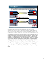
Attach Event
Plugging in a USB device to the host root hub or external hub is considered an attach
event. The device has a 1.5 KΩ pull-up resistor to the USB supply (VBUS). Pull-up to D+
signals a full speed device. D- is for low speed devices.
1.5KΩ
D+
D+
Transceiver
Transceiver
Full Speed Attach Event
D-
15KΩ
VBUS
D-
Device
15KΩ
Host or Hub Port
When no device is connected D+ and D- are at 0 V
1.5KΩ
D+
D+
Transceiver
Low Speed Attach Event
D-
15KΩ
VBUS
Transceiver
D-
15KΩ
Device
Host or Hub Port
7
So we have a USB device, a host and a USB cable. How does all of this
communication work? We have to first connect everything together. When we
plug the device together with the host it is called an Attach Event (similarly, when
we disconnect it is called a detach event). If you look at the initial condition for the
bus with no devices attached you will notice that the D+ and D- are at the same 0 V
potential because of the 15 Kohm resistors found on the host side. When the cable
is plugged in an endpoint device will provide a pull up resistor on either D+ or Ddepending on its speed capabilities. For a full speed device, the pull-up is attached
to the D+ signal. When the host detects this voltage change it will begin what is
called enumeration process at the full speed rate. If the voltage change is detected
on the D- line, then the enumeration happens at low speed. This attach event is
what signals the host that there is a new device attached to the bus. In MCU devices
the pull-up resistor should be integrated and it is just a matter of setting the bit in a
control register (i.e. the Pull-up Resistor Enable or PREN bit in the USB0XCN
register for the Silicon Labs USB family of MCUs). This is what gets everything
started.
7
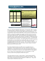
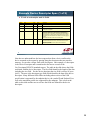
Packet Identifiers (PID)
The PID signals to the receiver that what the packet structure and content will be
and how the receiver has to respond
PID Type
PID Name
PID Value <3:0>
OUT
0001b
IN
1001b
PID - indicates transaction type and has different
meaning based on the transaction. Lower nibble is the
inversion of the upper nibble provided for error
checking.
SOF
0101b
Data – any information for the application
SETUP
1101b
Handshake – status information
DATA0
0011b
DATA1
1011b
ACK
0010b
NAK
1010b
STALL
1110b
Token
Data
Handshake
Start of Frame Marker (SOF) – Host can send this
marker at 1 mS intervals as a time base for peripherals
IN – data transfers to the host
OUT – data transfers from the host
SOF – Timing marker at 1mS
Setup – Specifies control transfers
Data0 – data transfer with data toggle clear
Data1 – data transfer with data toggle set
PID Format
PID0 PID1 PID2 PID3
PID0 PID1 PID2 PID3
ACK – data received without error
NAK – Device busy or no data available
Stall – Unsupported control request, control
request failed, or endpoint failed
8
Here we see the Packet Identifier (PID) structure. Be aware that “PID” is used for
two different things in USB (the second reference we will discuss later). The PID
we refer to here is what is sent out on the USB to define the transaction type. An
example PID, the Start of Frame (SOF) PID, is sent to provide a 1ms time base and
tells the receiving devices that the frame number associated with the current 1ms
timer marker follows the PID. The Data PID tells the system that the data for the
associated transfer is located in this transaction. Remember in USB the host always
initiates the transfer and data direction is with respect to the host. IN transfers data
from a peripheral device to the host. OUT transfers data from the host to the device.
From the table we can see that there are separate PID values associated with each of
the transaction types, IN or OUT and we can write the firmware to respond
accordingly based on the token that we receive. Do we need to be concerned with
the PID at the firmware level? No, as the hardware engine manages moving the
data between the FIFOs and the USB.
We mentioned the that the host in a USB system is responsible for power
management. The host sends the SOF every 1ms as mentioned. Devices are
required to enter a Suspend state after 3mS of inactivity per the USB specification.
Since there is constant activity on the bus when sending SOF PIDs, the peripheral
devices will stay out of suspend mode as the spec states that there is a 3mS
inactivity window before peripherals should enter suspend.
The Setup transaction specifies a control transfer. Control transfers MUST be
supported by all devices and their functions are defined by the USB spec. With
these, the host can gather data about the endpoint, set addresses etc. We get into
control transfers in detail later in the class.
8
Packets
Packets—block of information with a defined data structure. The packet is the
lowest level of the USB transfer hierarchy describing the physical layer of the
interface. If you were to monitor D+ and D- you would see the packet fields:
Packet identifier
Address
Endpoint
Data
Frame number
CRC
Token Packet format:
SOF Packet format:
Data Packet format:
Handshake Packet format:
9
Field
PID
Address
Endpoint
CRC
Bits
8
7
4
5
Field
PID
Frame Number
CRC
Bits
8
11
5
Field
PID
Data
CRC
Bits
8
0-1023
16
Field
PID
Bits
8
CRC covers everything in the packet with the exception of the PID which
has its own error checking mechanism
The Packet Identifiers we just reviewed are actually used to identify the packet type
being transmitted on the USB. We can see from the diagram above that the
packet format is defined by the PID we have outlined on the previous slide. For
example, if we see a PID of 0101b then we know to expect the data format of
the SOF packet. From that we know that the USB frame number will follow
the PID. The frame number is just a rolling count that will rollover on overflow.
If we were to see a PID of 1101b then we would expect a completely different
transfer type and there may be additional packets associated with the complete
data transfer. So we can see that the packet structure is a subset of the entire
transfer protocol defined by the USB. There are 4 packet types defined.
1) The token packet would be used to identify the transfer (setup, IN, OUT).
2) The SOF packet is sent on the frame boundaries to provide timing and frame
counts.
3) Data packet is the payload.
4) Handshake packets provide for comms robustness to verify that the data was
receive/transmitted properly.
9
Transactions
A transaction allows a set of operations to be grouped in such a way that
they either all succeed or all fail; further, the operations in the set appear
from outside the transaction to occur simultaneously. If the transaction
is unsuccessful then the host/device ignores any data that was received.
Transaction Types
SETUP:
Specifies a control transfer.
Setup transactions are always targeted to Endpoint 0 and are bi-directional (IN and OUT endpoint).
Has token and handshake phases with an optional data phase.
All USB devices must support setup transactions.
DATA:
The host is requesting to send(receive) data to(from) an endpoint.
IN – Responsible for sending data from the endpoint to the host.
OUT – Responsible for sending data from the host to the endpoint.
STATUS:
During control transfers the STATUS transaction uses the IN or OUT data phase to convey
success or failure of a transaction.
10
Take a moment to read the text in this slide as it conveys the key message regarding
transactions. A transaction is a combination of packets. For example, the Setup
transaction contains the Token packet we saw from the previous slide. With the
Token packet the host is transmitting the PID, the address and the endpoint number
of the device it wants to communicate with. The next packet it sends is the Data
Packet which tells the device that it wants to get/set some information from/to the
device. Next there is a handshake packet to signify a success or failure of the
transaction. So to review, the transaction is made up of multiple packets. In the
example provided, the setup transaction had 3 packets associated with it: token, data
and handshake.
There are three transaction types as listed in the slide. The Setup, Data and Status
transactions. Setup is used during the configuration process after a device reset.
The Data phase is used to transfer data to/from the device as requested by the host.
Taking the example we just gave with the Setup transaction it could be followed by
a Data transaction where the device can receive data that will set its address or it
could send data that tells the host what its vendor ID is. The Status transaction
identifies to the USB at a higher level than the handshake packet that a complete
transfer (multiple structured transactions) was successful. We will look at transfers
next.
After the device has been powered, it must not respond to any bus transactions until
it has received a reset from the bus. After receiving a reset, the device is then
addressable at the default address. The default address is address 0 and is termed
the Control Pipe.
10
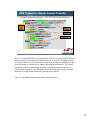
What is a Transfer?
The transfer is the process of
making a communications request
with an endpoint. Transfers
determine aspects of the
communications flow such as:
Data format imposed by the USB
Direction of communication flow
Packet size constraints
Bus access constraints
Latency constraints
Required data sequences
Error Handling
A transfer has one or more
transactions which then has one,
two or three packets
Transfer
Transfer
…
Transaction
Transaction
Transfer
Transfer
Transaction
Transaction
Token
Token Packet
Packet
Token
Token Packet
Packet
Data
Data Packet
Packet
Data
Data Packet
Packet
Handshake
Handshake
Packet
Packet
Handshake
Handshake
Packet
Packet
•Transfers are divided into transactions.
•Transactions are made up of packets.
•The host controls transfers by allocating transactions
to a frame.
•Transfers may span multiple frames.
11
We previously discussed how transactions are formed using multiple packets. Well
transfers are formed using multiple transactions. You can see from the slide that
hierarchy of the Transfer-Transaction-Packet relationship. The transfer is the
highest level followed by the transaction and then at the lowest level is the packet.
The red denotes the top level or Transfer, the yellow denotes the Transaction and
the green represents the actual packets. Both the transfer and the transaction are
logical implementations whereas the packets denote what you actually transmit
across the bus. A transfer is comprised of one or more transactions. Our example
from the previous slide showed three packets forming a single transaction. Lets
take that a step further. The example we gave is actually one transaction of what is
called a Control transfer that is formed by a total of three transactions. That first
transaction made up the Setup phase of the transfer. This is the phase that told the
device that the host is getting or sending configuration information and what that
information is going to be. A Data transaction then follows whereby the host either
sends the data it wants the device to use in order to configure certain parameters
(like its USB address) or it receives configuration data from the device that tells
how the device is set up to communicate. We would then have another transaction
to complete what is called the Status phase. This is a transaction that validates the
complete transfer (all three transactions).
11
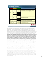
Transfer Format
Transfer Type
Stages
(Transactions)
Phases (Packets)
Comments
Setup
Token
Enables host to read configuration information, set addresses
and select configurations
Only transfer that is required to be supported by peripherals
Has both IN and OUT transfers to a single endpoint
Data
Handshake
Control
Data (IN or
OUT)
(optional)
Token
Status (IN or
OUT)
Token
Data
Handshake
Data
Handshake
Bulk
Data (IN or
OUT)
Token
Data
Handshake
Interrupt
Data (IN or
OUT)
Token
Data
Handshake
Isochronous
Data (IN or
OUT)
Token
Data
Non-critical data transfers
Bandwidth allocated to the host
Good for file transfer where time critical data is not required
Periodic transfers on the time base conveyed during
enumeration
Host guarantees attention before this elapsed time
Guaranteed delivery time of packets for data streaming
No-retransmitting of data allowed
12
Now that we have discussed the hierarchy of the USB protocol lets take a look at the different
transfer types. Remember, that these transfers are made up of transaction which are made up of
packets. Each of the transfer types is listed in the table along with the associated transaction and
packet types supported. The control transfer is the only bidirectional transfer allowed by the USB. It
is the transfer type used to communicate all of the configuration information between the host and a
device. Our example we provide on the previous slides illustrated the control transfer. It had the
three transactions associated with it. All devices on the bus MUST support control transfers to
endpoint 0. This is the default endpoint after reset and is at address 0. For Control transfers the status
phase is a zero length packet in the opposite direction of the transfer. For example, let’s say the host
is going to request a device descriptor which is a table we have loaded in flash. The direction of the
transfer would be IN since the data flows to the host. The status phase in this example would be a
zero length packet with an OUT token to terminate the transfer. Control transfers are used for things
like setting the device address to a value other than 0 for subsequent accesses, getting configuration
information on how the device wants to communicate using the other transfer types like Bulk.
Remembering our original example, we can see here that there are three transactions (Setup, Data,
and Status) comprised of nine packets (Token, Data, Handshake – three times) that make up the
Control transfer. The Bulk transfer uses three packets for the single transaction.
The Bulk transfer is used for non-critical data meaning data that is not required to be transferred on
any time base. It provides the highest data throughput as well so it is useful for applications like
printers, scanners or even USB to UART bridges. Remember that the host is responsible for
managing the bandwidth of the USB. One aspect of the Bulk transfer is that the host schedules
bandwidth as it becomes available, hence the non-critical nature of this type of transfer.
The interrupt transfer is used for periodic transfers where a time period is requested by the device
and the host will guarantee that the data transfer will be scheduled within that time period. It does
not guarantee that the data is transferred on a consistent time basis all the time, just that it will
schedule the transfer prior to the time period expiration. The data throughput is lower for interrupt
transfers and is useful for applications like mice, keyboards where user input is continually needing
to be sent to the host.
12
USB Transfers—A Closer Look
Control Write Transfers (OUT)—contains Setup, Data (optional), and
handshake transactions
Setup Transaction
SETUP
PID=1101
DATA0
PID=0011
ACK
PID=0010
Data Transaction
OUT
PID=0001
DATA1/0
PID=1011
ACK
PID=0010
NAK
PID=1010
Host sends Setup Packet followed by 8 bytes of data for
the request. The device must return an ACK.
Host sends OUT Packet along with the data for writes.
Device responds with handshake. No response indicates
a data error. DATA1 is first and alternates DATA0 and
DATA1.
STALL
PID=1110
Data error
Status Transaction
0-LENGTH
IN
DATA1
PID=1001
PID=1011
ACK
PID=0010
Data error
NAK
PID=1010
Data error
STALL
PID=1110
Host sends IN Packet for Status phase. Device responds
with a 0 length packet to indicate the success or failure
of the transfer. Host ACK the status. No response
indicates a data error.
Host → Device
Device → Host
13
In the next set of slides we are taking a look at the transactions and packets that
make up the different transfers and this slide shows the Control Transfer that is
sending data to the device. The colored boxes denote which direction the data is
flowing, whether it is from the host or the device. Keep in mind the host initiates all
transfers so the first box will always be yellow. The first transaction is the Setup
which is defined by the setup packet. Next we see the data that is sent in the request
from the host. The data sent in this phase is 8 bytes long and contains info about the
request, for example, if the host wants a device’s configuration or to set the device
address. After the data transaction the device ACKs the transaction. Next is the
data phase. Since this is an OUT control transfer the Data is yellow. The device
can either ACK, NAK or Stall the request. The ACK signifies that the transaction
was successful, the NAK means that the data either was not received correctly or
the device is not ready for the data. A Stall would mean that the device does not
support the requested feature. The Status phase for control transfers is just a 0
length packet in the opposite direction of the data phase. In this diagram the host
was sending the device information (OUT transfer) in the data transaction,
therefore, the in the status phase the host sends an IN token and the device responds
with a 0 length packet. These diagrams and the following flow diagrams like it can
be found in the book from Jan Axelson titled, “USB Complete.”
13
USB Transfers—Closer Look at a Control Transfer
Control Read Transfers (IN)—contains Setup, Data (optional), and
handshake transactions
Setup Transaction
SETUP
PID=1101
DATA0
PID=0011
ACK
PID=0010
Data Transaction
IN
PID=1001
DATA1/0
PID=1011
ACK
PID=0010
Data error
NAK
PID=1010
Data error
Status Transaction
0-LENGTH
OUT
DATA1
PID=0001
PID=1011
Host sends setup packet followed by 8 bytes of data for
the request. The device must return an ACK.
Host sends IN packet and the device responds with the
data requested. Host responds with handshake. No
response indicates a data error. DATA1 is first and
alternates DATA0 and DATA1.
STALL
PID=1110
ACK
PID=0010
NAK
PID=1010
Host sends OUT packet for status phase. Host responds
with a 0 length packet to indicate the success or failure
of the transfer. Device ACK the status. No response
indicates a data error.
STALL
PID=1110
Data error
Host → Device
Device → Host
14
Here we have the same transfer type as the previous slide except that the host is now
requesting data from the device. Therefore, the data direction for the Data
transaction and the Status transaction are reversed.
14
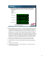
USB Transfers—Actual Control Transfer
Control Transfer Read Example — GET_STATUS command from Host
Transfer
Transaction
Packet
Hierarchy
SETUP Phase
DATA Phase
Status Phase
0 length field
15
Here is an actual USB analyzer capture of data traffic for a control transfer. This is a
control transfer (Get_Status) that a host has sent out to a device. Keeping in mind
our packet formats we can see the token packet identifies the first transaction as the
setup providing us with the device address and endpoint information. The second
transaction is the data phase using the address and endpoint and then the device
adds the data requested. The final transaction is the status phase using a 0-length
data packet to signify that the transfer completed successfully.
Note: Not all USB tools provide the data in the same format.
15
USB Transfers—Closer Look at Bulk/Interrupt Transfers
Bulk and interrupt transfers
Contains IN/OUT, Data, and handshake transactions
Bulk schedules transfers as bus bandwidth permits
Interrupt schedules transfers on regular intervals. Data may be delivered at a faster rate than the
endpoint descriptor value.
Data IN Transaction
IN
PID=1001
DATA
PID=1011
ACK
PID=0010
Data error
NAK
PID=1010
Host sends IN packet and the device responds with the
data requested. Host responds with handshake. No
response indicates a data error.
STALL
PID=1110
Data OUT Transaction
OUT
PID=0001
DATA
PID=0011
ACK
PID=0010
NAK
PID=1010
STALL
PID=1110
Data Size:
Bulk: 8, 16, 32, or 64 bytes
Interrupt: 1 to 64 bytes FS
1 to 8 bytes LS
Data error
Host sends OUT packet and then continues with the data.
Device responds with handshake. No response indicates
a data error.
Data transfer continues until the complete length of
data has been sent or a packet less than the minimum is
sent with a 0-length data packet.
Host → Device
Device → Host
16
All of the transfer types follow the same convention as the control transfer with the
exception that they differ in the number of transactions that are required to complete
the transfer. The Bulk and Interrupt transfers each have the same format and are
denoted by the IN and OUT PIDs. These transfer types use what is called the
MAX_PACKET_SIZE parameter (which is a USB parameter defined by in the USB
peripheral) to transfer the data. All data transactions must transfer the data in
multiples of the maximum packet size. If a packet less than the maximum number
of bytes is sent then it tells the host that there is not more data. If the data being
transferred is an even multiple of the MAX_PACKET_SIZE parameter then an
additional Data transaction needs to added with a Zero Length Packet (ZLP).
16
USB Transfers—Actual Interrupt Transfer
Bulk/interrupt transfer read example:
Interrupt
Transfer
IN
Transaction
Token
Packet
Data Packet
Handshake
Packet
17
Here is a screen capture of actual USB data traffic using these Bulk/Interrupt
transfer type. Notice that the transfer is composed of a single transaction.
17
USB Transfers—Closer Look at an Isochronous Transfer
Isochronous transfer
Contains IN/OUT and DATA transactions
Fixed transfer rate with a defined number of bytes transferred
Transferred in bursts
Host guarantees time scheduled transfers per frame
Insures data can get through on a busy bus even if the data does not
need to transmit at real time
Good for constant rate applications such as audio
IN
PID=1101
DATA0
PID=0011
Host sends IN packet and the device responds with the
data requested. No error checking.
OUT
PID=0001
DATA0
PID=0011
Host sends OUT packet and then sends the data. No
error checking.
Host → Device
Device → Host
18
This is the Isochronous transfer and as we mentioned earlier there is no handshake
packets associated with this transfer type.
18
USB Transfers—Actual Isochronous Transfer
Isochronous transfer OUT example:
OUT
Transaction
Transfer
Transaction
Packet
Hierarchy
Token
Packet
Data Packet
19
And a screen capture of the Isochronous transfer.
19
I Have to Know All of This?
What part of the low level USB information do I need to
be concerned with?
The USB transceiver and the Serial Interface Engine
(SIE) handles the low level USB interface and is done via
the hardware. We are primarily concerned with the
middle layer.
20
20
Silicon Labs Serial Interface Engine (SIE)
Serial Interface Engine (SIE) is part of the USB
hardware and handles data communications to
the host in hardware
Handles the handshake between the endpoint
and the host device
Generates an interrupt when valid data packets
received
Will not interrupt the CPU when an error in
transmission occurs
Moves valid data to/from the endpoint FIFOs
Firmware only needs to be concerned with the
data transferred
Handles all the bit stuffing required
21
SIE Handles
error checking
Token Packet
format:
Field
PID
Address
Endpoint
CRC
Bits
8
7
4
5
SOF Packet
format:
Field
PID
Frame Number
CRC
Bits
8
11
5
Data Packet
format:
Field
PID
Data
CRC
Bits
8
0-1023
16
Handshake
Packet format:
Field
PID
ACK
Bits
8
NAK
Firmware
interfaces
SIE Handles
handshaking
The hardware inside the MCU handles the low level communications in
conformance with the USB specification. The integrated transceiver handles all of
the electrical requirements for the differential signaling and the pull-ups etc. The
Serial Interface Engine (SIE) is a powerful peripheral that provides all of the low
level error checking and packet handling. When the packets come in from the host
the SIE will determine if the packet is valid based on the address and endpoint
number specified. It will also automatically generate the appropriate handshake
packet based on the current state of the MCU. The USB peripheral integrated
provides two interface points: the USB FIFOs and the USB control, status and
interrupt interfaces to the C8051F core. That is where the firmware developer can
read and write the data to be transferred as well as set the state of the USB
peripheral and service interrupts.
21
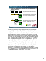
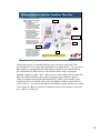
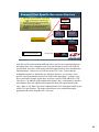
Different Devices and the Transfers They Use
What happens when all of
these devices are plugged
into the USB?
Interrupt
Host manages the bus
bandwidth upon
enumeration. If bandwidth
is not available the host
ignores the enumeration
request and doesn’t allow
the device access.
Mouse and keyboard use
Interrupt transfers to
provide timely responses
to user input. Interrupt
provides guaranteed
maximum latency.
Scanners and printers use
bulk since they are just
sending data files. Host
allocates the bandwidth as
it becomes available.
Bulk
Bulk and/or
Isochronous
Bulk
Interrupt
PDA/MP3 may use bulk for
file transfer to the device. If
it is some kind of audio
playback over USB then it
will employ Isochronous
transfers to guarantee the
data for constant rate
Bulk
Note: all devices use Control transfers to
Endpoint 0 for the Enumeration process
22
So now that we have covered the different types of transfers used in the USB
specification how do we apply those principals to our applications? Let’s say all of
these products are plugged into the USB and you turn the power strip switch ON.
We learned that all of these devices will initialize and be ready to respond to
endpoint 0 address 0, right? Well…there is always a hub (either external or the root
hub) and within the hub spec those ports are required to be enabled to operate.
There is a standard request SetPortFeature(RESET_PORT) which enables a port.
Technically the device should not be ready for endpoint 0 address 0 until the host
resets it anyway. It works because the host will enable one port that shows an attach
event, assign an address to that device and then can move on from there to the next
port. And so on, and so on…
22
USB Middle Layer
23
USB—Chapter 9
The host initializes a device through a series of device requests via
control transfers to Endpoint 0. These are defined by the USB specification
and have specific control transfer formats that we have discussed.
Chapter 9 Defines
The device states
The standard request format
The device descriptor format
The process used to transfer all of the configuration
information to endpoint 0 is called Enumeration.
The enumeration process begins
The host initiates a set of communication requests to the device to determine
the who, what, and how about the device
The device has pre-defined structures located in flash that describe what it
does and how it needs to do it
These are called descriptors
24
Chapter 9 of the USB Specification calls out the routing of data between the bus
interface (lowest layer) and various endpoints on the device. An endpoint is the
ultimate consumer or provider of data. It may be thought of as a source or sink for
data. We covered all of the different transfer types and how they are composed of
the different packet structures and also discussed that data phase of the transfers and
in which direction the data flows based on the request type. We have eluded to
things called request but really haven’t delved into it so far. Chapter 9 of the USB
specification outlines what all of the data in the Control Transfers means. If you
recall in our outline of the control transfer we mentioned that there are 8 data bytes
that get sent in the Setup phase. Those eight data bytes tells the device what
information the host is requesting. All of these requests are defined in the USB
specification, hence the term Standard Requests. In addition, the USB specification
outlines the format for the data that the host wants to receive from devices which
provides firmware developers the template required to store all of the configuration
information for the end device.
24
Enumeration—Loading Descriptors
Enumeration
//-----------------------------------------------------------// Sample Standard Device Descriptor Type
// Definition Fields
//-----------------------------------------------------------Length (18)
Descriptor Type (DEVICE, CONFIGURATION,
INTERFACE, ENDPOINT, HID)
USB Spec Release Number (0200h)
Device class (hub type…Human Interface defined in
other descriptor, CDC described here)
Device Sub-class (00h)
Device protocol (00h)
Maximum Packet size (64 bytes – max for the
endpoint)
Vendor ID (ID assigned by USB IF)
Product ID (ID assigned by product manufacturer)
Device release number (revision code of device)
Manufacturer (ABC Corp)
Product (string identifier)
Serial Number (1234)
Number of configurations (1 or more configurations
can follow)
VID/PID discussed next.
The activity that identifies
and assigns unique
addresses to devices
attached to a bus
Makes USB devices hotpluggable
The host is always checking
the bus for new devices via
Interrupt transfers
The host cannot
communicate with a USB
device until that device has
been properly enumerated
Invisible to user
This is loaded in the MCU memory.
25
We covered a lot of detail regarding USB transfers and the means by which the host
retrieves descriptors from the device. This whole process we are describing is
called Enumeration. After the attach event the host begins by resetting the device
and then sends a series of standard request to retrieve the descriptors. If the host can
accommodate the required bandwidth request by the device as well as the power
consumption if it is bus powered, then the host will go ahead and enumerate the
device and normal operation would begin. There can be no communication on the
bus without a successful enumeration. Once again this diagram is showing the
device descriptor as part of the enumeration. This is important because when we
attach a device there is a software driver that has to be loaded on the host in order to
let an application communicate over the USB to the device. We will cover that
next.
25
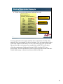
Enumeration: Finding a Driver
Once all descriptors are communicated, the Windows host searches for
a driver based on the vendor ID and product ID of the device
Vendor ID
[DeviceList]
%DESCRIPTION%=DriverInstall,USB\VID_1ABC&PID_2XYZ
[DriverCopyFiles]
usbser.sys
[DriverService]
ServiceType=1
StartType=3
ErrorControl=1
ServiceBinary = %12%\usbser.sys
Example entries of an INF file
Product ID
Host looks for driver info in the INF File:
• Host tries to match the Vendor ID
• Host tries to match Product ID
• If possible, host tries to find the Release number
Drivers listed for install
Configuration information
If the Windows host can’t find a matching INF file it will prompt for
the user to select a location where the files can be found for install
26
Remember that two of the fields in the device descriptor are the Vendor ID (VID)
and the Product ID (PID). The first descriptor the host will request is the device
descriptor and as such it will know what device it is communication with. The
Windows operating system (OS) will be able to search an inf file to see if it can find
a match between the VID and PID and what was received. If a match is found then
the driver that the OS needs to install will be called out and the OS can start it. If a
match is not found then the OS will prompt the user to find the driver to load. This
slide shows some excerpts from an INF file and is provided to show what the host
would be looking for in order to get the device up and running. In this case, a CDC
class device using the usbser.sys driver.
26
USB Descriptors
Descriptors
Data structures, or formatted blocks of information, that enable the host to learn about the device
Each Descriptor contains information about either the device as a whole or an element in the
device
The host uses control transfers to obtain the descriptors from the device
Descriptors typically reside in non-volatile data storage on the device. Most commonly set as C
structures or variables located in code space.
8051 Memory Example
Program Flash
16K bytes
Descriptor structures located
in code space in part of the
program memory.
In-System
Reprogrammable
Flash
8051 Internal Memory
Space
Descriptors
8051 External Memory
Space (XRAM on chip)
In-System
Reprogrammable
Flash
USB FIFOs for Endpoints
256
bytes
2048
bytes
8051 External Memory
Space (XRAM on chip)
27
In our discussions about control transfers and standard requests we have touched on
the information that is stored in the end device that the host reads to determine the
configuration and operating parameters of the device. The information is stored in
what is called descriptors. There are several types of descriptors that get stored in
the memory of the device and each provides configuration information associated
with a different aspect of the USB communications. For example, the device
descriptor provides high level information about the device. The endpoint
descriptor contains low level communication protocol specific information like
endpoint number etc. In this diagram we see that the descriptors would be stored in
the flash memory such that they are available after each power up and reset in order
for the host to read them. They are just variables in the memory that get passed to
the USB peripheral when the request is made by the host.
27
USB Descriptors Types
Device descriptor
General info about a USB device (vendor ID,
etc)
Contains info that applies globally to the
device
Only one device descriptor
Device
Device
Descriptor
Descriptor
Configuration
Configuration
Descriptor
Descriptor
Configuration descriptor
USB devices can have multiple
configurations
Each configuration contains one or more
interfaces
All associated interface and endpoint
descriptors get loaded with a request from
the host for the configuration descriptor
Contains fields like remote wake-up capability
and max power requirements
Interface descriptor
Lists the endpoint descriptors for the interface
Identifies if the interface belongs to a
predefined Class (such as the Human
Interface Device or HID)
Interface
Interface
Descriptor
Descriptor
Endpoint
Endpoint
Descriptor
Descriptor
HID
HID Descriptor
Descriptor
Endpoint descriptor
Info required by host to determine bandwidth
requirements
Describes endpoint number and address, IN
or OUT endpoint and the transfer types
requested
Report
Report
Descriptor
Descriptor
Physical
Physical
Descriptor
Descriptor
28
There is a hierarchy of descriptors specified in the USB specification. The device
descriptor is the top level descriptor that has global information about the device, in
particular are the maximum packet size (we touched on this earlier), the VID/PID
combination and serial number. Following the Device Descriptor is the
Configuration descriptor. Devices can have multiple configurations and they are
selected by the host. One of the key points when generating descriptors is that when
the host requests the Configuration Descriptor the device is required to send all of
the interface descriptors associated with that configuration as well as the endpoint
descriptors associated with the interface. The first field in a descriptor is the size of
the descriptor. In the case of the device descriptor the length is defined as the
length of just that descriptor. When the host asks for the configuration descriptor
the length field must be the sum of all of the descriptors to follow including the
configuration descriptor.
28
Example Device Descriptor Spec (1 of 2)
A look at a descriptor and its fields
Offset
Field
Size
Value
Description
0
bLength
1
Number
Size of this descriptor in bytes
1
bDescriptorType
1
Constant
DEVICE Descriptor Type
2
bcdUSB
2
BCD
USB Specification Release Number in Binary-Coded Decimal (i.e., 2.10 is 210H)
This field identifies the release of the USB Specification with which the device and
its descriptors are compliant.
4
bDeviceClass
1
Class
Class code (assigned by the USB-IF)
If this field is reset to zero, each interface within a configuration specifies its
own class information and the various interfaces operate independently.
If this field is set to a value between 1 and FEH, the device supports different
class specifications on different interfaces and the interfaces may not operate
independently. This value identifies the class definition used for the aggregate
interfaces.
If this field is set to FFH, the device class is vendor-specific
5
bDeviceSubClass
1
SubClass
Subclass code (assigned by the USB-IF)
These codes are qualified by the value of the bDeviceClass field
If the bDeviceClass field is reset to zero, this field must also be reset to zero
If the bDeviceClass field is not set to FFH, all values are reserved for
assignment by the USB-IF
29
Now that we understand how the host requests data from a device and how the
device responds to the request by passing along the descriptors that are stored in
memory, we can take a deeper look at the descriptors. One example of a descriptor
is the Device Descriptor and is transferred to the host as a result of the
Get_Descriptor(DEVICE) standard request. The table in the slide shows the fields
associated with the device descriptor. The first field identifies the length of the data
including the size field. For the device descriptor the size field is always 18 bytes
(0x12). The next is the descriptor type field which identifies the data as the device
descriptor. Many different fields follow including what revision of the USB
specification is supported by the endpoint device, the vendor ID and Product ID, as
well as the maximum packet size supported for the endpoint. Take a look at the
table on this slide and the next to see how the fields are defined for the device
descriptor.
29
Example Device Descriptor Spec (2 of 2)
A look at a descriptor and its fields
Offset
Field
Size
Value
Description
6
bDeviceProtocol
1
Protocol
Protocol code (assigned by the USB-IF). These codes are qualified by the value
of the bDeviceClass and the bDeviceSubClass fields. If a device supports classspecific protocols on a device basis as opposed to an interface basis, this code
identifies the protocols that the device uses as defined by the specification of the
device class.
If this field is reset to zero, the device does not use class-specific protocols on a
device basis. However, it may use class specific protocols on an interface basis.
If this field is set to FFH, the device uses a vendor-specific protocol on a device
basis
7
bMaxPacketSize0
1
Number
Maximum packet size for endpoint zero (only 8, 16, 32 or 64 are valid)
8
idVendor
2
ID
Vendor ID (assigned by the USB-IF)
10
idProduct
2
ID
Product ID (assigned by the manufacturer)
12
bcdDevice
2
BCD
Device release number in binary-coded Decimal
14
iManufacturer
1
Index
Index of string descriptor describing manufacturer
15
iProduct
1
Index
Index of string descriptor describing product
16
iSerialNumber
1
Index
Index of string descriptor describing the device’s serial number
17
bNumConfigurations
1
Number
Number of possible configurations
30
30
Device Descriptor Example
A look at a device descriptor declared in code:
//--------------------------// Descriptor Declarations
//--------------------------const device_descriptor DeviceDesc =
{
18,
// bLength
0x01,
// bDescriptorType
0x0002,
// bcdUSB
0x02,
// bDeviceClass
0x00,
// bDeviceSubClass
0x00,
// bDeviceProtocol
EP0_PACKET_SIZE,
// 0x40
0x10c4,
// idVendor
0x3413,
// idProduct
0x0000,
// bcdDevice
0x01,
// iManufacturer
0x02,
// iProduct
0x00,
// iSerialNumber
0x01
// bNumConfigurations
}; //end of DeviceDesc
Remember the length we asked
for in the device descriptor
example?
Tells how many bytes this
endpoint can handle
Strings
How many configuration
descriptors this device has
31
So what would a device descriptor look like when we determine all of the values
required? Here is an example of a device descriptor. You can compare these values
to the fields identified in the table to see how each value maps to the specification.
Shown in the slide is a descriptor for a standard class called CDC as the values
reflect the requirements of both specifications (USB 2.0 and the CDC class
specification). We have this labeled as const in order to have this stored in the nonvolatile flash memory so that we have them available all the time.
31
Getting the Descriptors
How does the host get all of these descriptors from
the MCU?
The Standard Request. The data passed as part of the
Setup phase of the control transfer is specified in the
USB specification and each byte has a specific meaning.
32
32
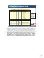
Standard Device Request Format
The host initializes a device through a series of device requests via control transfers to
Endpoint 0
These are defined by the USB spec and have specific control transfer formats
Offset
0
Field
bmRequestType
Size
1
Value
Bitmap
Description
Characteristics of request:
D7: Data transfer direction
0 = Host-to-device
1 = Device-to-host
D6...5: Type
0 = Standard
1 = Class
2 = Vendor
3 = Reserved
D4...0: Recipient
0 = Device
1 = Interface
2 = Endpoint
3 = Other
4...31 = Reserved
1
bRequest
1
Value
Specific request
2
wValue
2
Value
Word-sized field that varies according to
Request
4
wIndex
2
Index or
Offset
Word-sized field that varies according to
request; typically used to pass an index or
Offset
6
wLength
2
Count
Number of bytes to transfer if there is a Data
stage
Data format of
the 8 bytes
transferred
during the
Setup stage of
the control
transfer
33
Now we are getting into what is termed the Standard Requests or Chapter 9 of the
USB spec. Remember those 8 data bytes that was sent with the Setup token for
control transfers? The data that was sent during that request conformed to this
table. The first section defines the direction of the data flow with respect to the host
and what the target is, endpoint for example. On the next slide we will see the
values that can be used to fill the bRequest field as well as the others. Essentially
how these fields are set determine what the host is asking for and it is up to the
firmware to parse these fields and make decisions based on the values received.
33
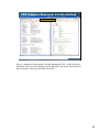
Standard Requests Values
These tables indicate the bRequest values and the wValue values defined by the USB spec
From the previous slide it can be seen that the wValue field can take on several different meanings
based on the request
bRequest Field: What request?
wValue Field: Get_Descriptor Request
Standard Request
Value
Descriptor Type
Value
GET_STATUS
0
DEVICE
1
CLEAR_FEATURE
1
CONFIGURATION
2
Reserved for future use
2
STRING
3
SET_FEATURE
3
INTERFACE
4
Reserved for future use
4
ENDPOINT
5
5
DEVICE_QUALIFIER
6
6
OTHER_SPEED_CONFIGURATION
7
SET_DESCRIPTOR
7
INTERFACE_POWER
8
GET_CONFIGURATION
8
SET_CONFIGURATION
9
GET_INTERFACE
10
SET_INTERFACE
11
SYNCH_FRAME
12
SET_ADDRESS
GET_DESCRIPTOR
wValue Field: Set_Feature Request
Feature Selector
Recipient
Value
DEVICE_REMOTE_WAKEUP
Device
1
ENDPOINT_HALT
Endpoint
0
TEST_MODE
Device
2
34
Let’s take a look at some of the values that are defined. Above we see the different
values associated with the fields that were in the table on the previous slide. These
are the values that get populated in the data for the setup phase of the standard
request (the 8 data bytes). For example, if the second byte (bRequest) is 0x06 the
host is requesting a descriptor or if it is a 0x05 the host is going to set our address.
The wValue field shown above goes deeper into the request. If we receive a 0x06
and have determined that the host is asking for a descriptor the wValue field will
tell us which descriptor the host is asking for. For example, if wValue is set to 0x01
then the host wants our device descriptor. As firmware developers we need to be
able to parse through the data received and take appropriate action.
34
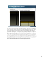
Standard Request Exercise
We are a host and we want to generate a request to a device in order to receive
it’s device descriptor
What values would we need to provide in our SETUP packet data phase?
Determine the data values we need to send to the device in order for it to respond with
its device descriptor values
Offset
Field
Size
Value
0
bmRequestType
1
0x80
1
bRequest
1
0x06
2
wValue
2
0x0100
4
wIndex
2
0x0000
6
wLength
2
0x0012
Notes:
1) The device descriptor is 18 bytes long (0x12)
2) The descriptor type is found in the MSB of the wValue field
3) Remember byte ordering
35
Here is an example of the values we would be parsing for a
Get_Descriptor(DEVICE) request from the host.
35
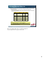
Standard Requests Example
Get_Descriptor(DEVICE): Standard request to get the device descriptor
bmRequestType = 80h, bRequest = 06h
(Get_Descriptor())
wValue = 0100h (DEVICE)
wIndex = 0000h
wLength = 0012h (18 bytes)
8 bytes of data found within the setup
phase of the control transfer.
Set_Address(3): Standard request to set device address to 3.
bmRequestType=00h, bRequest=05h
(Set_Address())
wValue = 0300h (Address 3)
wIndex = 0000h
wLength = 0000h (0 bytes)
36
Here are some captures of data highlighting the requests. The first is the
Get_Descriptor(DEVICE) standard request and the second is the Set_Address(3)
request. In the first example we would provide the USB peripheral with the data
that is stored that conforms to the descriptors for the device descriptor. When we
receive the second request we will update the address register with the value
transferred by the host, in this case we would become address 3.
36
USB—Device States (1 of 3)
After power up and throughout the enumeration process the MCU enters/exits several
device states
Idle state
All drivers are off. Device speed determines Idle state based on the pull-up
resistor attached. For full speed D+ is more positive than D- and vice versa
for low speed.
Suspend state
Low power state with < 500 uA current consumption requirement. If remote
wake-up capable then it is < 2.5 mA.
Remote wake-up — device has the ability to notify the host to start
transactions.
Timeout
After 3 mS of inactivity on the bus all devices are required to enter the Suspend
state
SOF marker devices keep devices out of suspend
Global suspend when host goes into standby
Selective suspend
Host can issue Set_Port_Feature request to put a specific device
into suspend
37
There are different device states defined in the USB specification. Take a minute to
familiarize yourself with those outlined here.
37
USB—Device States (2 of 3)
Resume
Any bus activity brings device out of suspend
Host places bus in Data K state for 20 mS then low speed EOP
Remote wake-up device drives the Data K state for 1 mS to 15 mS and then places
drivers in High-Z state
Powered
Device has been attached to the USB port and draws power from VBUS
It has not been reset
Default
Device has been reset from a powered state and has not been assigned an address
It responds only to endpoint0
Addressed
Device has been assigned its unique address from the host
Still not configured so it can’t be used yet
Configured
Device has passed the addressed state and has been configured
All functions may be used at this time
38
There are different device states defined in the USB specification. Take a minute to
familiarize yourself with those outlined here.
38
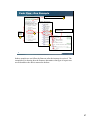
USB—Device States (3 of 3)
State diagram
39
There are different device states defined in the USB specification. Here is a
graphical view of the device states. As you can see they progress from the attach
event all the way to configured.
39
Device Classes
Device classes group common interfaces together
Class definitions specify the number and types of endpoints
May define data formats
May define functions or capabilities of devices within the class
Some types of defined classes
Human interface class
Communications device class
Hub class
Printer class
Mass storage class
Audio class
40
An additional set of specifications has been added to the overall USB 2.0
specifications. These additional specifications provide standard functionality using
a predefined set of rules to set up and enumerate as well as the endpoint types and
transfer types required. Along with defining exactly how the device will be
configured, there is also an associated driver already integrated to the OS. That
alleviates the need to write a custom drivers to suit the application. If the
application data bandwidth requirements can fit within one of these pre-defined
classes defined by the USB consortium then you can use that class and the driver
that is built into the OS. For example, we can configure our device to enumerate as
a Human Interface Device (HID) class and transfer data according to the HID
specification. The driver that communicates with our Windows application is
already a part of Windows and we didn’t have to write any driver code. Another
application is the use of the Communications Device Class (CDC) that can be used
for USB to UART applications and uses the built in Windows driver usbser.sys.
40
Human Interface Device (HID)
HID Class originally developed to for human interface objects such as
mice and keyboards
Interrupt transfers used for data transport
Any device can use the HID drivers. It does not need to be a human
interface device device.
Volt meters
Bar code readers
Thermometers
What do I need?
Firmware side
The firmware needs to set the standard descriptors and set the appropriate
report descriptors
Must support the standard requests as well as the HID specific requests
Host side
Need the Windows DDK to get the library functions to read and write the
data to the HID device
41
There are some things to be considered based on the class definition chosen for the
application. The next few slides discuss some of the standard classes and what is
required to implement them. For example, the HID class is useful for applications
where the data transfer rate is less than 64Kbps. This is due to the fact that it uses
interrupt transfers and they have a maximum packet size of 64 bytes and a minimum
interval of 1ms. If the application fits within those requirements then the
descriptors on the device side will need to reflect those called out in the HID
specification. The firmware will have to support the standard requests associated
with the USB 2.0 specification as well as those for the HID specification such as
Get_Report. On the host side the calls to the driver are available in the Windows
Driver Development Kit (DDK) or a manufacturer like Silicon Labs can provide
their own API.
41
Mass Storage (MSD)
Used for file transfer for memory sticks, etc.
Bulk transfers used for data transport
What do I need?
Firmware side
Firmware to detect and respond to Standard requests and the
Class specific requests
Standard and class specific descriptors defined
Typically SCSI interpreter is all that is needed, however, if access
to the file system is required by means other than the host USB
interface then a file system will also be required
Host side
File system access instructions such as fopen, fread, etc.
Any OS application like Windows Explorer can access the device
42
The same rules apply to the Mass Storage Device Class (MSD). When
implementing mass storage (like a USB drive) there are several firmware
considerations and application trade-offs to consider. Use this class when you want
to arrange data as files in order to move and copy them easily to other locations.
Typically, a SCSI interpreter is used and all of the file system structure is
maintained on the host PC. This is equivalent to a USB flash drive and using
Windows Explorer to access the files. One consideration to using the mass storage
device class is whether or not file access is to be given to another port other than the
host. In that case the firmware will have to implement its own files system and
need to respond to commands like fopen, fclose etc.
42
Communications Device Class (CDC)
Bulk transfers used for data transport
Any device can use the CDC drivers. It does not need to be
a modem device.
Volt meters
Bar code readers
Thermometers
Anything that requires a serial port input to the host uses the Abstract
Control Model (ACM)
What do I need?
Firmware side
Firmware to detect and respond to Standard requests and the Class
specific requests
Standard and class specific descriptors defined.
Host side
To use CDC, the host application opens the comm port assigned by
the operating system. MSCOMM is typical in Windows.
43
The communications device class (CDC) is used for quite a few applications.
Where it is most beneficial to embedded designers is the implementation of the
Abstract Control Model (ACM) which is a sub part of the CDC specification. The
ACM allows a USB device to operate as a USB to RS232 bridge. It requires the
descriptors to call out the CDC class and the firmware to be compliant to the USB
2.0 and the CDC specification. In addition the firmware is required to respond to
the class specific requests. An example would be the Set_Line_Coding which sends
the baud rate information in order to configure the integrated UART. So does a
CDC class device have to use a UART on the other end? No. We can just use the
class specific enumeration and the built in driver to the OS to provide the means to
pass data back and forth to the host. Once we receive it we can do anything we
want with it.
43
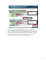
Example Class Specific Descriptor Structure
CDC Class uses the Abstract Control Model
**Device
Device
Descriptor
Descriptor
Bridge the gap between serial devices and
USB
Uses the Communications Class Interface
and the Data Class Interface
CDC defines a set of functional descriptors
as part of the Communications Class
Interface
Configuration
Configuration
Descriptor
Descriptor
Data
Data Class
Class
Interface
Interface
Descriptor
Descriptor
Standard descriptor using
values from the CDC spec.
Endpoint
Endpoint
Descriptor
Descriptor
Communications
Communications
Class
Class Interface
Interface
Descriptor
Descriptor
Endpoint
Endpoint
Descriptor
Descriptor
Functional
Functional
Descriptors
Descriptors
Endpoint
Endpoint
Descriptor
Descriptor
*Not all classes require specific
values in the device descriptor.
Descriptor Types
Standard
Standard
Class
Class
specific
specific
44
Now that we have discussed the different classes and we have mentioned that our
descriptors have to be compliant to the class specification as well as the USB 2.0
specification, let’s take a look again at the descriptor hierarchy for a standard class
implementation. In this case we will look at the CDC class. Notice that the
standard descriptors we had before are still there, however, we now have class
specific values populated in some of the fields of the descriptors. Looking at our
device descriptor example again, there are device specific fields added for a CDC
class device. In addition to the standard descriptors, deice, configuration, interface
and endpoint, there are additional descriptors the host will request based on the
class. Here we see Data Class and Communications Class descriptors added as part
of the CDC specification. The multi-colored boxes are a standard descriptor
populated with values from the CDC class spec.
44
USB Firmware
45
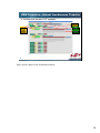
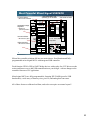
USB Firmware Descriptor Variable Defined
Device Descriptor Structures
46
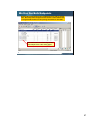
Here is a snapshot of some sample code that implements USB. On the left are the
definitions for the specific descripors and on the right is the actual code that places
these descriptor values into the flash of the MCU.
46
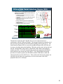
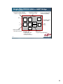
Code Flow—One Example
USB ISR Routine
ISR generated whenever USB event occurs
1
Handle_Setup Routine
4
Parse the
ISR to
determine
USB event
Data that gets written to USB
endpoint 0 FIFO
3
2
5
47
In these samples we can follow the firmware after the interrupt is received. The
example here is showing how the firmware determines what type of request was
received and how the data is returned to the host.
47
What is Required and Where to Get Help
Requirements
Vendor ID—obtained from the USB Forum
See following slide about how Silicon Labs can help
Product ID—unique number identifying the product family of the
equipment
Typically obtained from the USB Forum
Serial Number—unique identifier for each specific equipment
developed under the PID
Get help here
USB Implementers Forum (USB-IF)
www.usb.org
USB 2.0 specification
The USB class specific specifications
USB Complete by Jan Axelson
Special recognition needs to be given to Jan Axelson whereby
much of the material presented here is a direct reflection on the
excellent work from this reference
48
So we have completed the main portion of the training module that covers USB and
how it works. We have shown how the standard classes can benefit an application
by reduces development effort. Now that you understand USB we are going to give
a few tools that can abstract the entire USB operation to get a design
communicating via USB quickly. First, if you are going to be compliant to USB
and provide open functionality then you will have to obtain a VID from the USB
Implementer’s Forum. You can use the Silicon Labs VID and they can assign a PID
under their VID for customers to use. Also listed here are some useful guides to
learn USB in more detail. Thanks to Jan Axelson for the book “USB Complete” as
it has been an invaluable resource when putting this material together.
48
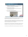
USB Solutions Offered by Silicon Labs
49
Certification and Compliance Testing
Silicon Labs allotment system
Silicon Labs has a unique VID (0x10C4)
If a customer uses the Silicon Laboratories VID, they must ask
Silicon Laboratories to assign a unique PID to their product
Contact Silicon Labs MCU technical support to receive a PID
USB Implementer’s Forum (USB-IF), found at www.usb.org
Assigns vendor IDs (VIDs)
Oversees compliance testing
USB products must pass compliance testing in order to display the USB
logo and to be listed on the USB-IF Integrators List
Contact Silicon Labs MCU support for help with compliance testing
50
Silicon Labs has an agreement with NTS (National Testing Services) to provide
discount USB Compliance testing for Silicon Labs customers. Contact
[email protected] for more details.
In order to display a USB certified logo on the end product or packaging, the
designers will have to undergo compliance testing. The USB implementer’s forum
has a list of approved compliance testing vendors. Once a product passes, the
vendor then has the product listed.
The forum also assigns a vendor ID (or VID) so that the designer can assign the
product with a unique ID number.
You can contact silicon labs for assistance.
50
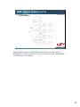
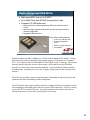
Silicon Labs USB MCU Products
Mixed-Signal USB 2.0 MCU solutions
48 MIPS core, 10-bit 200 ksps ADC, timers, comparators, UART, EMIF
On-chip oscillator, voltage regulator, and USB transceiver
Fixed function USB to UART bridges
The CP210x family of devices provides the easiest method for upgrading
legacy RS-232 systems with USB
Proven, royalty-free USB software solutions
Source code for drivers, transfer types, device classes, and enumeration
51
Silicon labs controller solutions fall into two main classes: fixed function and fullyprogrammable mixed-signal MCUs with integrated USB controller.
Fixed function CP210x USB to UART bridge devices with royalty-free VCP drivers
are the easiest and fastest way to add USB communication to your design – with no
changes to the controller firmware or PC application.
Mixed-signal MCUs are fully-programmable, featuring ISP FLASH (great for USB
bootloaders), a wide array of memory sizes, port I/O, and analog data converters.
All of these feature a calibrated oscillator, and so do not require an external crystal!
51
Highly Integrated USB MCUs
High-speed 8051 core up to 48 MIPS
Up to 64Kb Flash and 4K RAM for application code
Complete 2.0 USB feature set
Internal precision oscillator generates USB clock without external
crystal
Internal voltage regulator enables MCU to be bus powered without
external components
Integrated USB transceiver
Best-in-Class analog features
10-bit, up to 500 ksps ADC
On-board temperature
sensor
Precision voltage reference
Comparators
52
Digital peripherals include a SMBus, two UARTs, and an enhanced SPI module. Timing
functions can be achieved though the four general-purpose 16-bit timers or a 5-channel
PCA. Five full ports offer 40 controllable I/O lines which are all 5V tolerant. The external
memory interface provides access to data storage well beyond the on-chip XRAM or
provides an easy interface into external peripherals. System reliability features include a
watchdog timer, integrated power-on reset, a supply voltage monitor, and a missing clock
detector.
The F340 truly provides system on chip integration eliminating the unnecessary cost and
problems associated with adding external components.
The F340 and the other family members include everything needed to accomplish even the
most challenging embedded projects that also require USB connectivity. However, having
a powerful MCU is only the first step. A strong complement of hardware and software
development tools is a must if the overall project is to succeed.
52
Most Powerful Mixed-Signal USB MCU
In-system debug
No need for emulators
High-speed 8051 core
operating up to 48 MIPS
Up to 64 kB Flash
and 5376B of RAM
Integrated Voltage
Regulator
Allows bus
powered operation
Internal oscillator
No external crystal
17 ch. 10-bit, 200
ksps ADC
USB transceiver
No external resistors
53
Silicon labs controller solutions fall into two main classes: fixed function and fullyprogrammable mixed-signal MCUs with integrated USB controller.
Fixed function CP210x USB to UART bridge devices with royalty-free VCP drivers are the
easiest and fastest way to add USB communication to your design – with no changes to the
controller firmware or PC application.
Mixed-signal MCUs are fully-programmable, featuring ISP FLASH (great for USB
bootloaders), a wide array of memory sizes, port I/O, and analog data converters.
All of these feature a calibrated oscillator, and so do not require an external crystal!
53
Single-Chip USB to UART Bridge
CP210x family of devices
Fixed function USB to UART bridges provide
the easiest method for upgrading legacy RS232 systems with USB
Requires no firmware or driver development
Most integrated USB to UART bridge
solution
1024 Bytes of EEPROM for customization
Integrated transceiver
Integrated precision clock
On-chip voltage regulator
5x5 mm2 QFN28 package
Simplifies and enables legacy system
upgrades
Full royalty-free driver support
No software design needed
54
54
Single-Chip CP2103 USB to UART Bridge
Integrated voltage regulator
Allows bus powered operation
Integrated oscillator
No external crystal
4 Host controlled GPIO
LED drive capability
CP2103
VBUS
Voltage
Regulator
GPIO
48 MHz
Oscillator
Complete UART
Up to 1 Mbps
D+
USB
Transceiver
D–
USB
Function
Controller
640 B
TX Buffer
UART
576 B
RX Buffer
UART
I/F
(Modem)
1024 B
EEPROM
USB transceiver
No external resistors
EEPROM
Custom baud rates
Stores VID, PID
Security lock function
Data buffers
Supports high-speed UART
55
55
USB Software Support
Fixed-function Support Software
Full royalty-free driver support for Windows,
MAC OS, and Linux
WHQL certified
MCU Support Software
USBXpress:
Allows the developer to implement a USB
application without USB expertise
Royalty Free, Windows Certified Device
Driver that can be customized and
distributed
Design Examples:
Mass Storage Device (MSD) Data Logger
Human Interface Device w/ Boot Loader
USB Streaming Audio / Isochronous
Control, Bulk and Interrupt firmware and
driver examples
USB Mass Storage RD
56
Once the appropriate MCU or fixed-function solution is chosen, silicon labs also
provides a wide range of software solutions to enable the designed to quickly enable
the end application to communicate with the user’s application on the PC.
If this is your first time designing with USB connectivity, you may be interested in
some of the innovative reference design applications developed by silicon labs, such
as the USB FM radio or mass storage example.
As with all silicon labs MCU products, comprehensive, low-cost development tools
are available for easy evaluation and design.
56
USBXpress—Features
General USBXpress information
Implements a bulk pipe between host and peripheral
Operates at full speed using bulk transfers
Maximum transaction size is 4096 bytes
Max throughput = 960 kB/sec
Allocates one IN endpoint and one OUT endpoint on the
C8051F32x/34x devices
Multiple USBXpress devices may reside on the same bus
Distributed as a Keil software library
57
After the previous slides all of this makes sense right? The key to USBXpress is
that there is no OS driver development and it is easy to use. There is an Application
Programming Interface (API) that is defined that simplifies adding USB to a system
and it runs on any of the Silicon Labs USB product portfolio.
57
USB Development Solutions
Evaluation kits for USB/UART bridge
CP2102EK, CP2103EK
VCP Driver CD included
Full development kits for Flash-based
USB MCUs
CP2103 Evaluation Board
C8051F320DK
C8051F326DK
C8051F340DK
Integrated IDE, assembler, compiler,
linker, debugger
On-chip debug hardware (breakpoints,
watchpoints, single-step)
Mass storage daughter card
ToolStick daughter cards
ToolStick321DC
ToolStick327DC
ToolStick342DC
USB MCU Development Kit
Free downloadable USBXpress firmware
library and host side drivers
58
As with all silicon labs MCU products, comprehensive, low-cost development tools
are available for easy evaluation and design.
58
Learn More at the Education Resource Center
Visit the Silicon Labs website to get more information on Silicon Labs
products, technologies and tools
The Education Resource Center training modules are designed to get
designers up and running quickly on the peripherals and tools needed
to get the design done
http://www.silabs.com/ERC
http://www.silabs.com/mcu
http://www.silabs.com/usb
http://www.silabs.com/products/interface/usbtouart
To provide feedback on this or any other training go to:
http://www.silabs.com/ERC and click the link for feedback
59
Visit the Silicon Labs Education Resource Center to learn more about the MCU
products.
59
Appendix
An Actual CDC Class Enumeration &
Data Transfer Example
60
Enumeration
Tabular form of what we listed in our device descriptor structure.
Note the bDeviceClass is recognized as Communication
We were responding to
address 0 until the host
assigned us an address
2
Host sends Get_Descriptor(Device) request to find
out the max packet size and then resets the device
1
61
61
Get_Descriptor (Device)
Remember our exercise
slide 35?
We parsed the data and
returned the device
descriptor
Status phase terminating
the transfer
62
62
Passing the Config Descriptor (1 of 2)
Data toggle in action — our max packet size is 64
bytes. Our config descriptor is 67 bytes so we need
multiple data phases to complete the transfer.
All interface and endpoint descriptors
get transferred with the single
Get_Descriptor(Configuration) request
63
63
Passing the Config Descriptor (2 of 2)
The data shown corresponds to the data set-up in the USB_DESCRIPTORS.c
file. It is transferred in response to a Get_Descriptor(Configuration) request.
Last 3 bytes of the
configuration request
First 64 bytes of the configuration
including 2 interface descriptors and their
endpoint descriptors. The Abstract Control
Model values are part of this response.
64
64
More Enumeration
Why the red X? We broadcast USB 2.0 compliant so
this request is to find out if the device supports an
other speed. We don’t so we stall the response.
This is the class specific model we
use for USB to serial conversion
65
65
USB Setting the Baud Rate
When we set HyperTerminal to the baud rate and selected “Connect”,
the driver sends the device a command to set its UART to that rate.
Class request 0x20 is SetLineCoding.
0xE100 = 57600
Class request 0x21 is GetLineCoding.
We return what we received to verify.
66
66
We Use Our Bulk Endpoints
Now that the communications link is established we are ready to transfer
data. We hit keys while the HyperTerminal window is active and the host
is using the Bulk transfers we set up during enumeration to send data.
Bulk OUT transfers to send the keys we hit.
This example shows “hello” being typed.
67
67
www.silabs.com/MCU
68