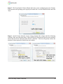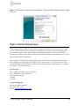
1
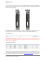
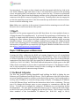
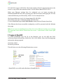
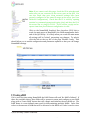
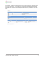
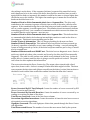
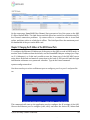
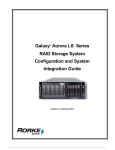
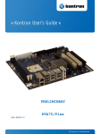
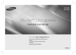
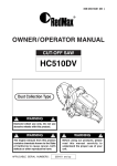
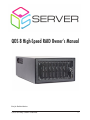
QOS 8 High-Speed RAID Owner’s Manual Not for Redistribution QOS 8-Bay User Manual 1 TABLE OF CONTENTS Chapter 1: Introduction ................................................................................................................... 3 1.1 About the QOS 8-‐Bay .................................................................................................................................... 3 1.2 Liability .............................................................................................................................................................. 3 1.3 Caution ................................................................................................................................................................ 3 1.4 Boot Up and Shut Down .............................................................................................................................. 4 1.5 Frontpane .......................................................................................................................................................... 4 1.6 Backpane ........................................................................................................................................................... 5 1.7 Drive Replacement ........................................................................................................................................ 5 1.8 HyperFS .............................................................................................................................................................. 7 Chapter 2: RAID Management and Administration ................................................................ 7 2.1 User Network Configuration ..................................................................................................................... 7 2.2 Logging into NumaRAID ............................................................................................................................. 8 2.3 Creating a RAID ............................................................................................................................................... 9 2.4 LUN Creation ................................................................................................................................................. 11 2.5 Scan & See Performance Stats ............................................................................................................... 12 2.6 Configurations and Log Files ................................................................................................................. 13 2.7 Users ................................................................................................................................................................. 16 2.8 Parameters ..................................................................................................................................................... 18 2.9 Datarate Statistics ....................................................................................................................................... 21 2.10 Datarate Graphs: ....................................................................................................................................... 22 2.11 LUN Details ................................................................................................................................................. 24 2.11 Slot Details .................................................................................................................................................. 25 2.12 SMART Info ................................................................................................................................................. 26 2.13 Sensors .......................................................................................................................................................... 28 2.14 Adapters ....................................................................................................................................................... 28 Chapter 3: Changing the IP Address of the QOS Ethernet Ports ...................................... 29 Chapter 4: Formatting a Direct-‐Attached Data LUN ............................................................ 30 4.1 Mac OSX ........................................................................................................................................................... 30 4.2 Windows 7 & 8 32 and 64 Bit ................................................................................................................ 32 Chapter 5: Contact Info & Technical Support ........................................................................ 36 QOS 8-Bay User Manual QOS Server is a subsidary of Ocean Tides Productions Ltd. © Copyright 2013 2 Chapter 1: Introduction 1.1 About the QOS 8-Bay The QOS is a standalone storage array, part of a file-‐based workflow involving one or more users and a single centralized storage system. The extraordinary power and versa-‐ tility of the QOS is one of the key features of this product. The QOS can be used to inte-‐ grate multiple users on shared storage volumes or function as a direct attached drive ar-‐ ray. It is powered by a multi-‐core processor, which is housed in an ultra-‐quiet and shock-‐ resistant chassis. The MDC is the embedded RAID controller housed inside in the QOS. It acts as a server that interacts with computers connected to it called clients and grants them access to the RAID storage drives. Read-‐write processes sent to the drives can be shared between mul-‐ tiple clients with the use of Rorke HyperFS SAN management, allowing instantaneous col-‐ laboration between workstations connected directly to the back or through a Fibre switch. 1.2 Liability In no event will Ocean Tides Production Ltd. Be liable for direct, indirect, special, inci-‐ dental, speculative or consequential damages arising from the use or inability to use this product or documentation, even if advised of the possibility of such damages. In particu-‐ lar, Ocean Tides Productions, ltd. Shall not have liability for any hardware, software, or data stored or used with the product, including the costs of repairing, replacing, integrat-‐ ing, installing or recovering such hardware, software, or data. 1.3 Caution • • • • • • • • Do not use any other power cable than a standard 120V 20A, do not modify any of the cables or connectors. Do not expose the QOS to water or excessive moisture and/or humidity. Do not install near heat sources such as radiators, heat registers, stoves, and other heat producing devices. Do not insert any objects into the grates on the front and back. Blocking any of the grates may cause damage to the unit. Do not apply force directly to the HBA interface cards on the back. Do not remove drives from the unit while it is running unless there is a failed drive. Drives take out of the unit while powered off to be put back in (ex shipping) must go back into the exact same slot they were in previously before it is powered back up – all drives must be returned before the RAID is powered on. Do not use any other model of hard drives than the exact same that came with your QOS system. If in doubt, check with QOS Technical Support. Be careful when moving the QOS unit not to expose it to excessive impacts and shocks. QOS 8-Bay User Manual QOS Server is a subsidary of Ocean Tides Productions Ltd. © Copyright 2013 3 1.4 Boot Up and Shut Down Some models of the QOS 8-‐Bay have a 0/1 power switch that sends power to the power supply. This has to be turned on before the power button is pressed to supply power and after the unit is booted down to fully power down. To begin using the QOS press the power button on the rear. The drive activity lights on the front will illuminate. The QOS 8 takes a couple of minutes to boot up, so wait approximately two to three minutes before turning on the clients. If clients are already booted, re-‐insert the Fibre Channel cable or reboot after two or three minutes. To shut down the unit, unmounts any volumes using Finder/Explorer and press and hold the button on the rear. 1.5 Frontpane The front panel of the QOS allows the user to gain access to the drive bay and view the drive status indicator lights. Green lights represent OK status and a red light indicates a drive is failing. The QOS drives are hot swappable, and can be removed by unscrewing the mounting screws holding the drives in place. Take care not to leave the front panel off and let excessive dust and debris enter through the front because it will be sucked into the system by the fans possibly causing damage. The front panel can be locked with a key, preventing access to the drives. 4 1 2 3 1 Mounting Screws secure each drive in place. Not securing all drives with a screw could lead to excess internal vibration. 2 Red Error light illuminates if the drive above it has failed. 3 Green Activity/Status OK light illuminates when the drive above it is functioning normally. When the array is reading or writing these lights will flash. 4 Enterprise quality Seagate Constellation drives. Do not use any other model of hard drive in the QOS Server system without approval from QOS tech support. Doing so could compromise the data on the RAID. QOS 8-Bay User Manual QOS Server is a subsidary of Ocean Tides Productions Ltd. © Copyright 2013 4 1.6 Backpane The backside of the QOS hosts all the adapters, Ethernet, Fibre Channel, 10GigE, power, diagnostic VGA and USB cables. Data ports such as Ethernet and Fibre Channel have green activity lights that indicate a healthy connection. On the back of the QOS there is a small power button, which can be used to initialize and shut down the device; when the activity lights on the front panel go out the unit is fully shut down. Some models have a 0/1 power switch on the back panel sends power to the power supply and should be shut off before unplugging the unit, and needs to be turned on (‘1’ position) before powering on. 6 3 7 4 5 1 2 8 1 2 3 4 5 6 7 8 Ethernet Port 0, one of two ports used to connect by TCP/IP to clients or switch Ethernet Port 1, one of two ports used to connect by TCP/IP to clients or switch ATTO 82EN (2port) 84EN (4port) Fibre Channel Host Bus Adapter w/ 850nm SFPs USB 2.0 ports for USB Keyboard or Mouse direct connection to Linux Red Hat OS VGA monitor port for direct connection to Linux Red Hat OS Power On/Off Button (some models also have a 0/1 power supply switch) Power Supply with 120V A/C power input PS/2 Keyboard and Mouse for connection to Linux Red Hat OS (mouse not re-‐ quired) 1.7 Drive Replacement There are eight hot swappable enterprise grade Seagate 1, 2, or 3TB drives in the QOS 8-‐ Bay system. These drives feed information to the QOS 8 System from the drive firmware such as factory information, total read/write errors, and temperature. In RAID6 mode (the QOS can also stripe as RAID0), two drives can fail on the system without losing any data. The drive that has failed will immediately be marked with a red light on the front QOS 8-Bay User Manual QOS Server is a subsidary of Ocean Tides Productions Ltd. © Copyright 2013 5 panel and will be displayed as ‘BAD’ in the NumaRAID software controller’s RAID Details menu. The system will continue to process read/write requests using parity information from the other seven drives. OK Drive Failed Drive NumaRAID RAID Controller Indicates the health of the drive in the Slots menu and the status of the drive in relation to the RAID is viewable in NumaRAID>RAID Details. NumaRAID>Slots Warning: The Slots menu only judges the health of the drives; reconstruction status is viewed only from the RAID Details menu. A drive that is reconstructing will still count as one less drive of redundancy. NumaRAID>RAID Details If a drive starts to fail it should be replaced immediately with a new working drive. Only spare drives provided by QOS Servers should be used for drive replacement, if any other drive should be used, please contact support at [email protected] for approval be-‐ QOS 8-Bay User Manual QOS Server is a subsidary of Ocean Tides Productions Ltd. © Copyright 2013 6 fore inserting it. To remove a drive, simply open the front panel with the key, look at the red ‘failed’ indicator light and follow it up to the failed drive, unscrew the mounting screw, and gently slide it out and place it into a static-‐free bag. To insert a replacement drive remove the drive from the packaging, and line up the connection interface with the connector in the QOS to ensure its going in correctly. Carefully slide it into the empty slot so that the mounting screw hole on the drive matches up with the hole on the enclosure. Secure it with the mounting screw. Note: Make sure each drive in the system is inserted with a mounting screw at all times. Excessive force could cause harm to the system. 1.8 HyperFS HyperFS is a file system supported by the QOS that allows it to host multiple clients ac-‐ cessing the same files simultaneously. It acts much like a gatekeeper of information. Hy-‐ perFS is a simple multi-‐OS solution to efficient sharable and scalable storage. After in-‐ stalling the client software from the Rorke website, you can instantly begin accessing sharable volumes. It is possible to configure multiple export entries for a single location on the server, allowing you to customize permissions for many different users. For more information on HyperFS set up consult the QOS HyperFS Manual available from our web-‐ site at http://www.qosserver.com/downloads. Chapter 2: RAID Management and Administration Creating the LUNs, configuring the RAID and running diagnostics are all accomplished through NumaRAID, the software RAID engine of the QOS 8-‐bay. There are no downloads or drivers required to access NumaRAID, configuration takes place over a direct Ethernet connection to the back of the QOS’s by typing the IP address into a browser followed by :10000 (ex: 10.0.1.101:1000). The IP and network information of both ports on the QOS 8-‐Bay can be customized, a process that is explained in Chapter 3. This Ethernet connec-‐ tion is only required for non-‐shared setups in order to manage the RAID; Ethernet con-‐ nectivity is not required to mount storage volumes. 2.1 User Network Configuration The first step towards opening NumaRAID and building the RAID is finding the two Ethernet port IP addresses on the QOS Server. The IP addresses of the QOS Server Ether-‐ net ports should be printed on a sticker on the back of the system. If you would prefer to use any other IP address or network settings, jump to Chapter 3 ‘Changing the IP Address of the QOS Ethernet Ports’ and follow the instructions there before continuing. The next step is to change the Ethernet ports on your computer to communicate with the QOS Server. To learn how to configure the computer’s IP Address see your Operating System documentation. The port used for connection must be set to a value on the same ‘range’ as the IP of the port you will be plugging into on the QOS Server. The IP range is the first three numbers of the four-‐number IP address (ex: 10.0.1.101 range is 10.0.1, QOS 8-Bay User Manual QOS Server is a subsidary of Ocean Tides Productions Ltd. © Copyright 2013 7 192.168.2.101 range is 192.168.2). The fourth number of the IP cannot be the same as the server’s or any of the other attached clients. Use the Subnet Mask 255.255.255.0. When your Ethernet settings have be configured you can begin accessing the Webmin/NumaRAID back end by opening your Internet browser and typing the IP of the connected Ethernet port followed by :10000. See the example below. IP of Server Eth0 port: 10.0.1.101 Subnet Mask: 255.255.255.0 Client Ethe0 port: 10.0.1.105 Subnet Mask: 255.255.255.0 To access NumaRAID type 10.0.1.101:10000 in Safari/Firefox/Chrome from client If the Ethernet has been successfully configured you will be presented with the Webmin intro page. Note: If you can’t see anything and you have the correct Ethernet settings, try restarting the client and if that doesn’t work reboot the server. If that doesn’t work contact QOS support. 2.2 Logging into NumaRAID To access NumaRAID type the IP of the Ethernet port on the QOS into Safa-‐ ri/Firefox/Chrome followed by :10000. (Ex: 10.0.1.101:10000). Enter the following login information when prompted. Username: admin Password: password This will take you to the following Webmin intro screen: …NumaRAID is accessible under Hardware>NumaRAID GUI QOS 8-Bay User Manual QOS Server is a subsidary of Ocean Tides Productions Ltd. © Copyright 2013 8 Note: If you cannot reach this page, check the IP for mistakes and make sure you are connected to the correct port on the QOS. You can also check that your client network settings have been properly configured to the same IP range as the server (see User Network Configuration). Check that the IP is valid by opening terminal or command prompt and typing ‘ping’ and then the IP of the server like so: ping 10.0.1.101. If you receive a reply and re-‐ sponse time then your Ethernet configuration is valid. Click on the NumaRAID Graphical User Interface (GUI) link to reach the main menu of NumaRAID, the RAID management back-‐ end of the QOS 8-‐Bay. It is likely when you reach the main menu all settings will be ‘locked,’ preventing any changes. To unlock, click the link at the top left of the page ‘Module Config.’ This should allow you to enable configuration and parameter updates so that you can change NumaRAID settings. 2.3 Creating a RAID If it is your first time using NumaRAID the RAID Status will read ‘No RAID’s Defined.’ If there are available drives, then fields will be present to name and configure a new RAID along with a ‘Create RAID’ button that will commit and initialize the new RAID set. The RAID Name is a user-‐defined name used for differentiating multiple RAIDs. Cache Size refers to the amount of RAM that will be allocated to the RAID set. Cache is used to store QOS 8-Bay User Manual QOS Server is a subsidary of Ocean Tides Productions Ltd. © Copyright 2013 9 data before it is written to the drives and achieves faster speeds by using memory con-‐ nected directly to the motherboard. Although a large cache will generally lead to better performance, it is not recommended to use up all the RAM memory for drive caching, as a minimum of 2GB is required for running the Operating System and managing other tasks. 8GB is a good size for the QOS 8-‐bay RAID system. RAID Level determines if the data will be striped as RAID0 or RAID6. RAID0 stripes data across all eight drives, but since there is no built-‐in redundancy a single drive failure will prevent access to all the data permanently. RAID6 takes up the capacity of two drives to write parity – data that contains restore information -‐ to all drives. RAID6 can see two drives completely fail without losing any data. RAID6 will help protect against errors as well as failures and is the recommended configuration for mission critical data manage-‐ ment work. There isn’t a great deal of performance difference between the two levels. First Slot and Device Count allow you to define which drives will be allocated to the new RAID set. Most of the time it is best to start at drive 0 and use up all of the QOS 8-‐Bay’s eight drives as a single RAID set. On the far right, the RAID status is a quick way to tell if there are any errors on the RAID including a failed drive restore operation. If there aren’t any serious problems the RAID will show as Online. After the RAID has been created you can click the ‘Details’ button to view and change its parameters. Warning: In the Raid Details page and subsequent pages, it is possible to irrecoverably delete the RAID. Do not do anything to an existing RAID without being assured it will not compromise your data (especially Scan/See Performance Stats). The RAID Details panel at the bottom is for viewing the status of the RAID. If a drive has failed and a replacement drive has been inserted, the drive will show its reconstruction QOS 8-Bay User Manual QOS Server is a subsidary of Ocean Tides Productions Ltd. © Copyright 2013 10 status on this page. This is the only page that contains information about the state of the drives in the RAID. The Slots menu only indicates the physical health of the hard drives. 2.4 LUN Creation Logical Unit Numbers are logical storage used as the building blocks of a RAID set. A LUN is a logical unit of the total storage that is used for determining how the disk space will be accessed; ie: as two disks, as a data and metadata disk, etc. In order to successfully use the RAID from attached clients and other devices at least one LUN is required. HyperFS Shared File System requires a minimum of two LUNs, a Metadata and Data LUN. The Name, Size, and Offset fields on this page should be filled out first before clicking the Create button to create the LUN. The LUN Name is a user-‐defined name for identifying the LUN between systems. The Size is the total size in GB of the LUN and the Offset must be filled in when creating multiple LUNs where each LUN capacity has a value to be offset by the total of preceding LUNs. The following is an example of multiple LUNs from a sin-‐ gle RAID set. Total RAID Size: 4000GB LUN 1 SIZE: 2000 OFFSET: 0 LUN 2 SIZE: 2000 OFFSET: 2000 LUN 3 SIZE: 2000 OFFSET: 4000 LUN 4 SIZE: 2000 OFFSET: 6000 HyperFS Shared File System requires a Metadata and a Data LUN for each of its volumes. The Metadata LUN is used to manage various file management processes. A 120GB Metadata LUN size should be large enough for the QOS 8-‐Bay system to work with Hy-‐ perFS, and the rest of the available drive space can go towards a single Data LUN (with an offset value of 120GB). QOS 8-Bay User Manual QOS Server is a subsidary of Ocean Tides Productions Ltd. © Copyright 2013 11 2.5 Scan & See Performance Stats The Scan & See Performance Stats button located to the left of the RAID Name on the RAID Details page allows you to gather test information by performing read/write tests on the drives in the QOS 8-‐Bay RAID. Warning: Performing a Write Scan will completely erase the contents of the RAID being tested. The data on the RAID will be irrecoverably lost. After clicking the Sequential Scan button, a dialogue will appear with the Read/Write speed of the RAID in MBps. Returning to the RAID Details page will display each drive’s device By-‐ID and the results of the scan test in a table. The upper table refers to drive read test results, and the one below it refers to drive write results. You can use the RAID Surface Scan menu to select a scan type (Read/Write) and a file size to be used for the test. The total hard drive sectors that fell within a certain response time will be allocated to the different table columns. Some variation is normal as the hard drives scan the outermost sectors of the drives where it takes longer to access data. If there are an unu-‐ sually large number of sectors frequently falling in the right-‐most columns, check the SMART status information of those drives to see if it is defective. QOS 8-Bay User Manual QOS Server is a subsidary of Ocean Tides Productions Ltd. © Copyright 2013 12 2.6 Configurations and Log Files From the main NumaRAID menu Configurations and Log Files displays diagnostic infor-‐ mation, creates logs for technical support, and transfers and archives config files. The Config file stores information about the state of a RAID set. ‘Save Current Config As’ uses a Linux path with a file name to create a back up of the cur-‐ rent RAID config. The config file stores information about the RAID, LUNs, ports, files, sensors, slots, licenses, parameters, and drives. It is written to both the SATADOM boot disk and the drives in the RAID. ‘Reload Configuration’ gives you the ability to reload the current config or load a config from anywhere on the disk. Record Current Configuration to All Drives writes an updated version of the config file to the drives in the RAID, and Re-‐ cover Configuration from Drive to File will write a config file for a given drive individually. Caution: Reloading the current config will temporarily disconnect all clients. Underneath the Configurations options there is the Trace File Actions table. Trace is a record of logged information about QOS 8-‐Bay’s system used for monitoring, trouble-‐ shooting, and support. ‘Display Trace’ will use the Type and Number of Entries filters to output a list of the Trace details logged by the system. You can select to display only Commands or select All to display all information. The Number of Entries column is used to choose between the First 25 or Last 25 Entries to display. Capture Trace to TraceFile will record these entries QOS 8-Bay User Manual QOS Server is a subsidary of Ocean Tides Productions Ltd. © Copyright 2013 13 to a saved text file using the First or Last selector followed by the number of entries re-‐ quired. Control Trace can start, stop, or reset a Trace display in progress. The Trace details page can be used to check for bad sectors, drive read/write errors, and stuck processes. When you click the ‘Display Trace’ button from the Configurations and Log Files menu, the Trace Details are shown as above. The Previous 25 Trace Entries or Go To Entry fields allow you to navigate forward and backward to specific entries. Time: The time the command started. It will almost always be the same for all 25 entries, unless a process is taking longer than it should. Entry: The entry number of the command used for reference. You can use the ‘Go to En-‐ try’ field to jump to a particular entry. uGap: The time in microseconds between this event and the next event in line. uSecs: The time in microseconds it took to complete the command. User: The name of the user that performed the command. Lun#: The number of the LUN that was targeted by the command. Lun: The name of the LUN that was targeted by the command. CDB: “Command Data Block” describes the command that took place. In the chart above ‘READ’ means the array was reading from disk. ‘10’ refers to the block size of the transfer operation – 10 bytes. Logical LBA: Is a reference to the logical sector among the Hard Drives that the command had targeted. QOS 8-Bay User Manual QOS Server is a subsidary of Ocean Tides Productions Ltd. © Copyright 2013 14 Dirty: Indicates the existence of Dirty segments in the cache (‘Dirty’ refers to a cached file that is inconsistent with the server). This value should be 0 for all commands. Status: Either displays 0 or 1 to inform the user if the command was successful (0) or if it failed (1). To display the Trace information in a more visual form, click the ‘Switch to Chart Display’ button below the Trace log. 1 2 3 4 5 6 7 8 9 10 1 LBA (Logical Block Address) Graph displays the logical sectors that the RAID opera-‐ tions are targeting. It is the number/sector where the virtual ‘head’ is positioned. The values are graphed as sector (Y) against Entry Number (X). This example shows a straight line because the process was a sequential read operation. QOS 8-Bay User Manual QOS Server is a subsidary of Ocean Tides Productions Ltd. © Copyright 2013 15 2 Transfer Length Graph shows Transfer length (Y) against Entry Number (X). In this case as all transfers were 1024 Bytes so the graph is a straight line. 3 Cache Access time shows the amount of time allowed to the Cache (Y) against the Entry Number (X). This graph is likely to be non-‐linear. 4 Command Execution Time displays the time it took to complete the command (Y) against the Entry Number (X). This graph is also likely to be non-‐linear. 5 Data Transfer Rate displays the average Megabytes per second for a transfer (Y) against the Entry Number (X). 6 Command Transfer Rate shows the average Megabytes per second for a command (Y) against the Entry Number (X). 7 The number of Write Backs (Y) against Entry Number (X). 8 The number of Read Aheads (Y) against Entry Number (X). 9 The number of Non-‐Real Time Commands (Y) against the Entry Number (X). 10 The number of Dirty Cache Segments (Y) against the Entry Number (X). Below Trace there is a small table to manage the Log File for the QOS RAID system. Click-‐ ing the ‘Display’ button will display the Log file for the entire system. Our technical sup-‐ port team uses these logs to troubleshoot the QOS RAID. The Reset button clears the cur-‐ rently recorded Log and starts out new. Clicking Display will show a list of the operations that took place on the system along with their date and time. QOS technical support will instruct you on how to save logs for trou-‐ bleshooting purposes. 2.7 Users The User Details menu shows a list of the current sessions, providing options to create Users and promote Real Time Users. The Sessions table describes the users connected to the QOS RAID and their WWNs (World Wide Names). Creating a user makes it easier to identify a connected computer system, but it is not required. To create a user, fill out the Name and WWN columns in the Users table with the information from ‘Session Status’ and click the Create button. The delete button will remove that user from the list non-‐ QOS 8-Bay User Manual QOS Server is a subsidary of Ocean Tides Productions Ltd. © Copyright 2013 16 destructively. At the top of the page there is a list of the current users, and below that a list of ‘Real Time Users.’ A Real Time User is a user that requires higher priority to the bandwidth. You can select from the dropdown list who will be promoted to a real time user. QOS 8-Bay User Manual QOS Server is a subsidary of Ocean Tides Productions Ltd. © Copyright 2013 17 2.8 Parameters The parameters menu is accessible from the main NumaRAID menu and sets out the overall NumaRAID settings that will apply universally. The following settings are availa-‐ ble: Maximum Read Ahead Distance in 128k Stripes: When you playback video for exam-‐ ple, you are essentially doing one large sequential read. To make playback smoother, the array can be set to read more of the file than the position that the client computer is cur-‐ rently requesting. This is called a read-‐ahead cache. The cache is only selectable in 128KB increments, and the value here is the number of 128KB blocks to use (The blocks are referred to as stripes, because they go across all of the drives in the RAID). The de-‐ fault value is 24. This allows the computer to read 3MB ahead. So, for example, if you were playing a standard definition video file, which plays relatively slowly in relation of the array, when the computer playing the video starts playing at 12MB of the file (for ex-‐ ample), the array has already read the next 3MB, and is ready to play up to 15MB, without doing any disk activity. As the computer plays through this cache, it is refreshed with new data as necessary. Making this setting it too high would cause kind of a stopping/starting of data reading on the array, and setting it too low would render the cache not as effec-‐ tive. Stripes Required in Memory before Read Ahead Allowed: This is the amount of se-‐ QOS 8-Bay User Manual QOS Server is a subsidary of Ocean Tides Productions Ltd. © Copyright 2013 18 quential data that must be read in order to trigger the read-‐ahead cache above. The de-‐ fault value, 24, (using the same stripe value as above 128KB), means that the client must request 3MB of sequential data in order to activate the cache. Setting this value too low would force the array to re-‐cache over and over as fragmented files occur. Setting it too high might force it not to cache something that otherwise would benefit the client. Maximum Read Ahead Commands Outstanding: While the array will appear to be sending and receiving data, the client is also sending commands to the array to tell it to read or write data. The client, for example, might send a request to the array to send back (read) 1MB of data, however before the array has finished, the client might send a request to the array to send back another 1MB. This is happening anywhere up to millions of times per second. This setting controls how many of those commands will be buffered at a time. The default value of 8 is good for most cases. Setting the number too low may re-‐ sult in jerky playback -‐ i.e. the computer sends a request, the array sends back the data, then waits for the next request. Setting it too high would just waste memory. Number of Stripes in Each Read Ahead Request: This can control the size of each re-‐ quest. The default value is 8 (x 128KB), which is 1MB. This keeps the data coming from the array at a consistent rate -‐ i.e. if the requests from the client were not limited, the re-‐ quests might be uneven, possibly interrupting playback for other clients. Enable Random Reads: The array is capable of applying the read-‐ahead cache to non-‐ sequential sectors/stripes. The default value enables this. If it is disabled, the read-‐ahead will only apply to sequential reads where the sectors/stripes themselves are sequential. Cache Flush Percentage Threshold (0-‐100): This controls how often when writing, that the cache should write its contents to disk and empty itself. The default value is 10 (%), which means that when the cache is at least 10% full, it should empty. The cache size which was chosen when the RAID was created has a direct bearing on this setting. For example, if you used a cache size of 3GB, and this value is set to 10, then the write cache will flush when it is roughly 300MB full. The default number is fine in most cases. If you set the number too low, you will disable the effectiveness of the write cache, as it will be emptying more often. If you make it too high, you risk having to wait for a larger cache flush. Maximum Write Back Requests Outstanding: Just as you can control how many com-‐ mands the read will buffer, you can also control the amount of commands that the write will buffer. The default value of 8 is good for most cases. Setting the value too low or too high may result in dropped frames on capture because either you are not allowing the cli-‐ ent computer to send enough write commands, or are accepting too many. Setting the value too high will waste RAM. Number of Stripes in Each Write Back Request: This setting controls a limit on the amount of cache to use for each write command from a client. The default value is 8, which is 1MB. This is fine in most cases. Making the value too low would limit the cache too much. Making it too high would probably just waste RAM. QOS 8-Bay User Manual QOS Server is a subsidary of Ocean Tides Productions Ltd. © Copyright 2013 19 Percent of Cache Available to Non-‐Real-‐Time Writes: This applies to the real-‐time us-‐ ers. You can actually dial-‐down the cache for writing for non-‐real-‐time users. This value is a percentage. The default value of 50, indicates that real-‐time users only get a maxi-‐ mum of 50% of the cache. Setting this value too high would render this setting useless. Setting it lower would further limit the cache for non-‐real-‐time users. Keep in mind, this setting only applies to non-‐real-‐time users -‐ see below for real-‐time users. Note that this setting applies globally to all non-‐real-‐time users. Percent of Cache Available to Real-‐Time Writes: This is the same as above, but only applies to real-‐time users. The default value of 75 indicates that a real-‐time user gets 75% of the cache for writes. Setting the value higher could impact non-‐real-‐time users more. Setting it lower gives up some of the cache to the non-‐real-‐time users. It's almost the opposite of above. Note that this setting applies globally to all real-‐time users. Max Data Rate of Non-‐Real-‐Time Requests (MB/SEC) 0 for no limit: This allows you to limit the bandwidth of non-‐real-‐time users in megabytes per second. It is used to free up bandwidth for real-‐time users as well. The value entered here is in megabytes per se-‐ cond. The default value, 0, does not limit the maximum data rate for non-‐real-‐time users. Max Number of Non-‐Real-‐Time Requests: Another way of limiting non-‐real-‐time users is to limit the amount of read/write commands they can send. Note that this setting af-‐ fects all non-‐ real-‐time users. The default value is 4. Setting the value lower would further limit non-‐real-‐time users. Setting it higher would cache more requests. Reconstruct in Advance of Drive Completion: If a drive isn’t performing as well as the rest, this option is used to base the data on the parity, instead of the data returned from the drive. In many cases, this can compensate for a slow drive. This option is disabled by default. Reconstruction Priority (from 0 to 100): The array is capable of reconstructing while it is being used. This value controls the balance of priority given to reconstruction versus the data access. The default value is 0, which means reconstruction is only performed when the array is idle. If you set it to 100 (which is definitely not recommended), the ar-‐ ray would run very slowly to the clients, while reconstructing at full speed. So as an ex-‐ ample, consider a value of 10 -‐ This would mean that the array would spend 10% of it's time while being accessed, doing reconstruction. The value is up to you -‐ the more time and/or speed you can sacrifice while the array is being used to reconstruction, the faster the reconstruct will complete. Enable PQ Verification: Default is No. This value is a form of error-‐detection and cor-‐ rection (Raid-‐6 only). If this value is enabled, while the array is reading, it will compare the data read against the two parity generators -‐ there has to be a 3-‐way match between the data and each of the two parity generators. If there isn't, the data from the parity gen-‐ erators is used instead of the data from the drive in question -‐ this substitution is made in real-‐time. So basically, if the array detects something wrong in the data, it corrects it. En-‐ abling this option might affect read transfer rates. QOS 8-Bay User Manual QOS Server is a subsidary of Ocean Tides Productions Ltd. © Copyright 2013 20 Internal Diagnostic Message Level: More explicitly, this value determines what you want the internal diagnostics to log. Here are the values and what they do: Disabled: Do not log anything. Requests: Only log read/write requests. State Started: Only log state engine starts. State Ended: Only log state engine completions. BIO Started: Only log Block I/O starts. BIO Ended: Only log Block I/O completions. Cache Monitor: The cache. Debug Monitor: Debugging. Performance: Monitor performance. Target: Monitor targets. Silent Data Corruption: Monitor for the problem described under PQ Verification. The Display button on the bottom of the table, displays the diagnostic message log. Note that it is important that this function only be used when directed to do so, and it must be disabled when not in use, otherwise it would fill up the boot drive. 2.9 Datarate Statistics The QOS has very powerful tools to monitor current system performance over time in re-‐ lation to earlier data recordings. Data Rate Statistics from the main NumaRAID menu presents stats for the overall NumaRAID system, User IO, as well as RAID, LUN, and Adapter traffic. The graphs are divided into three groups of six that represent the same data values recorded at different times (a day ago, an hour ago, etc.). The Datarate Op-‐ tions table is used to define the device that the graphs will reference. To see statistics for a certain category click the Chart button beside it. All graphs display red bars as write operations and green as reads. QOS 8-Bay User Manual QOS Server is a subsidary of Ocean Tides Productions Ltd. © Copyright 2013 21 2.10 Datarate Graphs: 1 2 3 1 Real Time Data Rate of the chosen device (Y) against time in seconds (X) recorded last minute and this minute. A useful tool to use during long copy and paste opera-‐ tions to test the speeds of the transfer at different points in time. 2 Real Time Data Rate of the chosen device (Y) against time in seconds (X) recorded last hour and this hour 3 Real Time Data Rate of the chosen device (Y) against time in seconds (X) recorded last day and this day QOS 8-Bay User Manual QOS Server is a subsidary of Ocean Tides Productions Ltd. © Copyright 2013 22 1 2 3 1 Number of commands (Y) within a specific response time range (X) recorded last minute and this minute. A useful tool for analyzing the strength of the NumaRAID application and QOS hardware. 2 Number of commands (Y) within a specific response time range (X) recorded last hour and this hour 3 Number of commands (Y) within a specific response time range (X) recorded last day and this day QOS 8-Bay User Manual QOS Server is a subsidary of Ocean Tides Productions Ltd. © Copyright 2013 23 1 2 3 1 Number of commands (Y) against specific transfer size rangers in KB (Y) recorded last minute and this minute. If the QOS has heavy I/O traffic, this feature will help get a sense of the fluctuations in load over time. 2 Number of commands (Y) against specific transfer size rangers in KB (Y) recorded last hour and this hour 3 Number of commands (Y) against specific transfer size rangers in KB (Y) recorded last day and this day 2.11 LUN Details The LUN details menu is accessible by clicking on the Details button beside a LUN in the RAID Details sub-‐menu of NumaRAID. If all you need is a MBps reading of the perfor-‐ mance of a specific LUN, this menu has the tools to do it. There is a dropdown menu for selecting between a Read Scan or Write Scan test and a test size. Read Scan is non-‐ destructive, it is a direct indicator of the internal bandwidth of and individual LUN to the RAID system. The test results that appear after clicking the Sequential Scan button show the MBps of the LUN scan. In addition to testing, this menu can also be used to delete a LUN with the Delete button. Warning: A Write Scan will erase the data on the LUN, so be very careful about using this method. QOS 8-Bay User Manual QOS Server is a subsidary of Ocean Tides Productions Ltd. © Copyright 2013 24 2.11 Slot Details SLOT Details – accessible from the main NumaRAID menu – offers a way to check on the health status of drives in the QOS 8-‐Bay system and read detailed information about drives from firmware with SMART (Self-‐Monitoring, Analysis, and Reporting Technology). The Slot Details will not indicate the status of a reconstructing drive. It is a rather poor indicator of the condition of the RAID itself, because it only shows whether the drives are healthy (OK) or failed (BAD) even though a reconstructing drive will still count as a single drives worth of lost redundancy. Starting from the left, the first column called ‘Number’ refers to the device number of the drive; the QOS 8-‐Bay drive device numbers will always read 0-‐7. The next three columns outline manufacturer information such as source company and product model. Capacity shows the total amount of data the drive can hold in Gigabytes, and the next two columns display the name of the hard drive as it is seen by the QOS 8-‐Bay’s Linux operating sys-‐ tem. The Status column reflects if the drives are functioning normally (OK) or if there has been a failure (BAD). The SMART feature enables the NumaRAID GUI to read information from the firmware on the drives such as physical temperature readings and logged read/write errors. SMART is an invaluable tool to keep tabs on the strength and vitality of the hard drives in the sys-‐ tem. SMART updates are run automatically every few minutes. QOS 8-Bay User Manual QOS Server is a subsidary of Ocean Tides Productions Ltd. © Copyright 2013 25 2.12 SMART Info Device: Shows the manufacturer, model number, and firmware revision of the de-‐ vice. Serial Number: Is the serial number: Note that the actual serial number is just the rightmost 8 characters. The rest of the string is a manufacturer-‐unique ID. Device Type: Shows the type of the de-‐ vice. Transport protocol: Connection type -‐ i.e. SAS or SATA Local Time: Shows the time that this command was executed. SMART Feature: Indicates whether or not the drive supports the SMART feature, and whether or not it is enabled. Temperature Warning: Indicates wheth-‐ er or not a temperature warning is enabled or disabled. Overall Health: Indicates the drive Health at the time this command was executed. Current Drive Temperature: This is the temperature (in Celsius) at the time the command was executed. Drive Trip Temperature: Indicates the maximum internal temperature that the drive ever recorded. Elements in Grown Defect List: The drive keeps track of different areas that it cannot write to. These are called “surface defects.” There are two defect lists: One is the Manu-‐ facturing Defect List, which contains defects that were found when the manufacturer test-‐ ed the drives. This list is fixed and never changes. The other list is called a grown defect list, which is a list of defects that occurs after the drive leaves the manufacturer. This list only gets bigger, hence the “grown” name. Vendor Cache Information: This is just a category heading which describes the next 5 lines. Blocks Sent to the Initiator: In the case of SAS, the host adapter channel is called an ini-‐ tiator, while the drive itself is the target. This line indicates the number of blocks of data sent to the initiator – in this case, the blocks are 512 bytes (sectors), however they may or may not be data from the disk – they could also be SMART data such as the one which was requested here. Most of the time, these are drive data sectors, so in general, this is the number of sectors that has ever been read from the drive. Blocks Received from the Initiator: In general, this is the number of sectors written to the drive. Blocks Read from Cache and sent to the Initiator: This is an indicator of how efficient QOS 8-Bay User Manual QOS Server is a subsidary of Ocean Tides Productions Ltd. © Copyright 2013 26 the caching is on the drive. If the computer (initiator) requested the same block twice, and it happened to be in the cache of the drive, then the drive would not have to read it again from the disks, so in general, this number would be the same or always higher than the Blocks sent to the Initiator. The higher the number goes, it means the less work the heads on the disks have to do. Number of Read or Write Commands who's size <= Segment Size: The drive only sends data to the computer in groups of blocks, into an area of the cache, called a cache segment. If the commands being sent or the data being sent back is smaller or the same size as a cache segment, it would register here. This number doesn't necessarily indicate something good or bad – just a number of commands sent which were not the same size or smaller than the cache segment – most are not. Number of Read or Write Commands who's size > Segment Size: This indicates data or commands which had to be broken up into multiple transfers to send to the drive or the computer. This doesn’t mean anything good or bad. Vendor (Factory) Information: This is a category heading for the next two lines. Number of Hours Powered Up: This indicates how long a drive has been powered up (in hours), regardless of whether or not it was reading or writing – even just sitting idle counts as being powered up. In fact, if the drive had power and was put to sleep, it would also be counted here. Number of Minutes until next SMART test: The drive has two diagnostic tests. One is a quick test, which only takes a few seconds, and is run by the drive itself (if not manually triggered). The other is a full surface scan, which is only initiated by the user. In this ex-‐ ample, there is 1 minute until the drive is going to run the quick test on itself. The quick test is how the drive updates this information. The next section shows the Error Counter log. The output, when viewed with a fixed-‐ space font, forms a table – below is a sample of what that table might look like. The three rows separate the data into reads (data accessed from the drives), writes (data written to the drives), and verifies (data verified by reading/checking the data after a write). Errors Corrected By ECC Fast/Delayed: Counts the number of errors corrected by ECC (Error Correction and Control). Errors Corrected By Rereads/Rewrites: Counts the number of errors corrected by re-‐ reading or rewriting the data on the drive. Total Errors Corrected: A sum of the first three columns. Correction Algorithm Invocations: Counts the number of times the total errors correct-‐ ed required correction algorithms. Gigabytes Processed: The total Gigabytes of data that passed through the Error Correc-‐ tion Algorithm. Total Uncorrected Errors: The number of errors that were never fixed by the system. QOS 8-Bay User Manual QOS Server is a subsidary of Ocean Tides Productions Ltd. © Copyright 2013 27 2.13 Sensors The Sensors menu shows real time feedback about different hardware components in the system such as the CPU, motherboard power output, and CMOS battery. Values are up-‐ dated each time this page is loaded. They define the lower and upper limits of acceptable usage and warn if there is any malfunction with the monitored components – like for in-‐ stance if power output is below an acceptable level. If any sensors in the QOS system show status bad, call QOS Technical Support as soon as possible. 3.3V: The +3.3V power output as seen from the motherboard. This voltage is especially important for the CPU. 12V: The +12V power output as seen from the motherboard. This voltage is especially important for powering the motors on the hard drives as well as the fans in the system. 5V: The +5V power output as seen from the motherboard. This voltage operates the ma-‐ jority of electrical circuits within the system. Batt: The voltage of the CMOS battery. This battery retains the settings for booting the array when the system is off or unplugged. 2.14 Adapters The Adapter Details menu contains information about the Fibre connection status and al-‐ lows you to manually configure the Network settings for the QOS 8-‐Bay’s two Ethernet ports. If it is not possible to connect to NumaRAID to change the IP Address, the next best way is to use the keyboard and monitor or Telnet approach outlined in Chapter 3 ‘Chang-‐ ing the IP Address of the QOS Ethernet Ports.’ The table at the top of the Adapters menu labeled NumaRAID Network Management will have two ports listed, Eth0 and Eth1, that represent the two Ethernet ports on the back of the QOS. There is a dropdown to enable DHCP (Dynamic Host Configuration Protocol) and a field to manually enter a static IP and Subnet Mask. Unless it is used in an advanced network set up, the QOS 8-‐Bay should have a static IP ad-‐ dress with DHCP disabled. In direct-‐attached applications, the two ports can be config-‐ ured as the same IP, but in shared environments the two ports should be set on separate IP Ranges to avoid conflicts. IP Range refers to the first three numbers of the four number IP Address. One example of a usable shared configuration would be Eth0 10.0.1.101 and Eth1 10.0.2.101. An example of direct-‐attached clients would be Eth0 10.0.1.101 and Eth1 10.0.1.101. When connecting a client computer to the Ethernet port, the first three numbers must fall in the same Ethernet range as the QOS Server port address and the fourth number should be different from all other devices on the network. For more in-‐ formation on Client Network Configuration see the Chapter 1 ‘Client Network Configura-‐ tion.’ An Ethernet connection is only required in non-‐shared setups to managing the RAID, and is not required to access the storage. QOS 8-Bay User Manual QOS Server is a subsidary of Ocean Tides Productions Ltd. © Copyright 2013 28 On the same page, NumaRAID Fibre Channel Ports presents a list of the ports on the QOS 8’s Fibre Channel HBA. The Link Status and Link Speed are useful for troubleshooting Fi-‐ bre Channel connection problems. Up status refers to a connection that is in-‐use and online, and down refers to a link that is offline. The Link Speed lists the maximum possi-‐ ble bandwidth of the port on the HBA card. Chapter 3: Changing the IP Address of the QOS Ethernet Ports To configure the Ethernet IP Addresses of the ports on the QOS to work in DHCP mode, or another static IP address than the default, use the NumaRAID Adapter settings (see Chap-‐ ter 2.14 Adapters), or if this isn’t possible access the Linux part of the QOS MDC server using direct keyboard and monitor connection to the back or SSH protocol and the login information username: root password: rdserdse. Type in the Linux command: system-‐config-‐network-‐tui Use the arrow keys to select an Ethernet port to configure, port 0 or port 1 and press En-‐ ter. This command will start up the application used to configure the IP settings of the QOS. Choose the Ethernet port to configure (eth0, eth1) and enter the desired IP, Subnet and QOS 8-Bay User Manual QOS Server is a subsidary of Ocean Tides Productions Ltd. © Copyright 2013 29 turn DHCP on and off using the space bar. When finished navigate to the OK button and hit Enter. Warning: If you plan to connect two shared clients into the two different Ethernet Ports, put the two ports on different IP Ranges (Ex. 10.0.1.101 and 10.0.2.101) in order to avoid IP conflicts. After the network settings of the QOS have been set, navigate to the Quit button using the arrow keys to exit the application. A reboot of the QOS Server is required for the IP changes to take effect. Chapter 4: Formatting a Direct-Attached Data LUN After the RAID and it’s LUNs have been created in NumaRAID, the Ethernet is no longer required to format the QOS 8 storage as a HFS or NTFS file system. Note: If you are using HyperFS or a similar shared file system on the QOS disregard this Chapter completely. 4.1 Mac OSX Directly after being created, the LUN(s) created with NumaRAID will be detected by Mac OSX assuming a valid Fibre Channel connection is present. A Disk Insertion pop-‐up will appear for each LUN cre-‐ ated with NumaRAID. Click the Initialize button or open disk utility from Ap-‐ plications/Utilities/Disk Utility. QOS 8-Bay User Manual QOS Server is a subsidary of Ocean Tides Productions Ltd. © Copyright 2013 30 Step 1: Click on the Fibre Channel LUN in Disk Utility. Note: Make sure you have the correct drive selected so that you don’t wipe out any other data unintentionally. Step 2: Click the Partitions Tab QOS 8-Bay User Manual QOS Server is a subsidary of Ocean Tides Productions Ltd. © Copyright 2013 31 Step 3: Select 1 Partition from the Volume Scheme drop down menu. Step 4: Name the Partition as desired, and set the format to Mac OS Extended (Jour-‐ naled). Click Apply to apply the changes. Warning: This will erase all data on the LUN. 4.2 Windows 7 & 8 32 and 64 Bit The LUN(s) created using the NumaRAID GUI will appear in Windows Disk Management assuming a valid Fibre Channel connection is established. 32-‐Bit and 64-‐Bit Operating system may differ slightly, for instance the Initialize Disk pop-‐up may not appear in some 32-‐Bit Operating Systems. Keep in mind the NumaRAID GUI must be used for LUN crea-‐ tion over 2TB in a 32-‐Bit Windows OS. QOS 8-Bay User Manual QOS Server is a subsidary of Ocean Tides Productions Ltd. © Copyright 2013 32 Step 1: Right click on My Computer and select Manage. Step 2: From the options on the left hand size, choose Disk Management, in 64-‐Bit Oper-‐ ating Systems, the Initialize Disk pop-‐up will appear. Warning: Proceeding from here will erase all data on the LUN. QOS 8-Bay User Manual QOS Server is a subsidary of Ocean Tides Productions Ltd. © Copyright 2013 33 Step 3: If the Initialize Disk window comes up, choose GPT (GUID Partition Table) from the Partition Style selection box. Step 4: Right click on the LUN in Disk Management and click New Simple Volume QOS 8-Bay User Manual QOS Server is a subsidary of Ocean Tides Productions Ltd. © Copyright 2013 34 Step 5: The New Simple Volume Wizard will come up for configuring the new Volume. The first menu will prompt you to Specify a Volume Size. Use the default full size and click ‘Next.’ Step 6: In the Format Partition screen, choose ‘Format this volume with the following settings’ of the two selection boxes. Choose NTFS File System and Give the new volume a name, and check the ‘Perform Quick Format’ checkbox. This box will greatly reduce the amount of time required to format the new volume. QOS 8-Bay User Manual QOS Server is a subsidary of Ocean Tides Productions Ltd. © Copyright 2013 35 Step 7: Click finish to complete the installation. The new NTFS volume should be ready to be use. Chapter 5: Contact Info & Technical Support When you purchase a QOS Series product we provide additional technical support to go with it. This includes but is not limited to installation assistance, troubleshooting with our certified support team, and product specification inquiries. We are committed to providing the most secure and cost effective hardware solutions and instant access to our professional support engineers. Our promise is to maximize the potential of your QOS product by making sure that you have things up and running safely and securely. We're here to serve you with our tech-‐ nical knowledge and experience whether its individual guidance and inquiries or industry assistance, you can count on us. QOS Servers Tel: 1 (888) 788-‐5496, (604) 739-‐8434 1429 Dominion Street, Unit #102 North Vancouver, BC Canada V7J 1B4 Technical Support Mon-‐Fri 9:00am–6pm PST Tel: (604) 351-‐5701 E-‐Mail: [email protected] QOS 8-Bay User Manual QOS Server is a subsidary of Ocean Tides Productions Ltd. © Copyright 2013 36