1
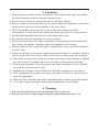
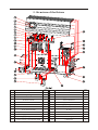
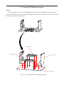
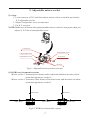
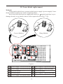
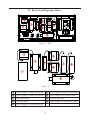
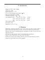
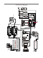
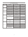
YX-2007
Show-Pro (RGB) Laser
USER MANUAL
www.yagang.com
Version 1.2
2006.4.24
1) Open the box for checking • • • • • • • • • • • • • • • • • • • • Pa ge 1
2) Installation • • • • • • • • • • • • • • • • • • • • • • • • • • • • Pa ge 1
3) Attention • • • • • • • • • • • • • • • • • • • • • • • • • • • • • Pa ge 2
4) Warning • • • • • • • • • • • • • • • • • • • • • • • • • • • • • Pa ge 2
5) Structure of the fixture • • • • • • • • • • • • • • • • • • • • • • Pag e 3
6) Control board instruction • • • • • • • • • • • • • • • • • • • •
Pa ge 4
7)Control PCB Replacement• • • • • • • • • • • • • • • • • • • • Page 5
8) Sc an m ot or R ep la ce me nt • • • • • • • • • • • • • • • • • • • • P ag e 6
9)Adjustable mirror holder • • • • • • • • • • • • • • • • • • • • • Page 7
10)Laser diode replacement• • • • • • • • • • • • • • • • • • • • • Page 8
11)Electrical diagram of laser • • • • • • • • • • • • • • • • • • • • Page 9
12 )D MX 51 2 Op er at e • • • • • • • • • • • • • • • • • • • • • • • •
Pa ge 10
13 ) Specification • • • • • • • • • • • • • • • • • • • • • • • • • • • P ag e 11
14 ) Maintain • • • • • • • • • • • • • • • • • • • • • • • • • • • • •
Pa ge 11
15 )E le ct ri ca l di ag ra m • • • • • • • • • • • • • • • • • • • • • • • • Pa ge 12
16 )Tr ou bl e sh oo ti ng • • • • • • • • • • • • • • • • • • • • • • • • • Pa ge 13
Please read over this manual before operation the light
1. Open the box for checking
In order to use this product safety and reasonable for the users, please read over
this manual carefully before use and the operation must strictly according to this
manual to avoid any damage to the product and personal safety.
Once after received this products please take and put carefully. And check
carefully that whether the product was damaged or not during the transportation and
please check the following things were enclosed:
Laser light 1PCS
Graphics USB card 1PCS
9 pin signal line 1PCS
USB connection cable 1pcs
3 pin signal line 1pcs
User manual 1pcs
Power cable 1PCS
Install CD-ROM 1PCS
2. Installation
1. Please check the voltage whether is the same with the one showed
on the
equipment or not.
2. It must ask for the technical person and set the light safety when installation. And
let the light beam at the suitable angle.
3. When install this equipment please make sure there's no flammable surfaces
(decorated things, etc) within at least 1.5M and maintain minimum distance of
0.5M from the equipment to the walls.
4. Please make sure that there's no other equipment or decorating materials
obstructed the exhaust fan and the vent-pipe.
5. Products should be install immobility.
6. In case of safety, it's very important that to connect the earth with line.
1
3. Attention
1. Must operate according to the user manual. Don't separate the light personally.
Call the technician when the machine breaks down.
2. Please do not see the laser beam directly to avoid any damage.
3. Before connect or disconnect the power, please adjust the luminance of the laser
diode to the least to avoid any damage to the laser diode.
4. This unit should be keep dry, do not use in the rain or dank and dusty
environment. It can be use in the outdoor with the water-proof cover protector.
5. Set the light immobility and try to avoid strong shake or hit.
6. Prevent dust into the equipment to avoid problems.
7. Please keep that there's no other equipment or decorating materials obstructed
the exhaust fan and the vent-pipe when the equipment was working.
8. Before connect power, check the plug is immobility or not, power line should be
connect well.
9. Please do not open or close the equipment frequently that's to avoid any affect to
the life span of the laser diode, and try the best to avoid the long time working.
10. Due to the characteristic of the laser diode, after three hours working, it should
be close at least 25 minutes until the laser diode cooling then work again.
11. Don't touch the light or draw the power line when your hand was wet. And do
not pull the electronic power line.
12. Maintain the distance at least 10M above from the equipment to the object.
13. This equipment does not have any parts can repair for the users, please do not
open the equipment.
14. When the laser diode became dim or damaged please contact the dealer timely.
15. To use the original package when transport again and to avoid shake.
4. Warning
1. Don't look the light directly to prevent make some destroy with eyes..
2. Keep the space between light equipments and the lighted things more than 10 M.
2
5. Structure of the fixture
No .
Description.
Qty
No .
Description.
Qty
1
Lens cover
1
13
AC 220V fan
2
2
Dustproof glass
1
14
8
3
Reflect bowl
1
15
DC 12V fan
Power supply 1 of blue laser diode
4
Red laser diode
1
16
4
5
Blue laser diode
1
17
Feet of machine
Power supply 1 of red laser diode
1
1
1
6
X scan motor
1
18
Power supply 1 of green laser diode
7
Y scan motor
1
19
Green laser diode
1
8
Scan motor holder
1
20
X scan
1
9
Adjustable reflect mirror holder
2
21
Control board
1
10
Power supply 2 of blue laser diode
1
22
1
11
Power supply 2 of green laser diode
1
23
TTL switch board
Power supply
12
Power supply 2 of red laser diode
1
24
Connector
1
3
1
6. Control board instruction
7
6
ILDADB-25F Connector-IN
ADDRESS
ILDADB-25F Connector-OUT
IN
ON
Remote Lock
Security
key switch
DMX
OUT
ON
OFF
OFF
POWER INPUT
1 2 3
1
2
3
4
5
4
5
Remote Lock In the event of removal, laser will not emit any beam.(E.U. IEC regulation)
Security key switch Laser diode ON/OFF
POWER ON/OFF Power switch
POWER INPUT Input power, with inner fuse.
DMX IN/OUT DMX signal input/output
6
ILDA DB 25 F Connector: signal input connection port of the laser perform
software that in accordance with the ILDA standard.
7
ADDRESS: the 10th code is switch code. When the 10th code is OFF, 1~9 are
function codes. When the 10th code is ON,1~9 will be DMX address codes.
The address code of first light usually by 1, the second light is 14 and so on.
NOTE:
1. When ILDA DB 25F connector
s connection port are free, the lamp will drive
by the inside program, temporality it can control by DMX 512 signal.
2. After connect the ILDA DB 25F, The lamp will change to ILDA connected port
drive mode ,this connection port can receive all the signal of laser perform
software that accord with the ILDA standard, such as LD-2000 of Pangolin
Company.
DMX address code setting:
in the binary, each digit have
switch situation.
Example for DMX address code:
DECIMAL
BINARY
LSB
0
1
14
511
0
or
1
just correspond to
USAGE OF DIP SWITCH
MSB
1 2 3 4 5 6 7 8 9 10 ON
OFF
1 2 3 4 5 6 7 8 9 10 ON
OFF
1 2 3 4 5 6 7 8 9 10 ON
OFF
1 2 3 4 5 6 7 8 9 10 ON
OFF
4
OFF
or
ON
7. Control PCB Replacement
Steps:
Disassemble defective PCB and then assemble new PCB.Make some marks of
cable connection of refer to electrical diagram so that the connection of cables shonld
be exactly same as original one.
Control PCB
X scan PCB
Y scan PCB
Signal switch PCB
Fig 7-1 Control PCB Assembling Diagram
5
8. Scan motor Replacement
(1) Steps:
1. Unscrew UK M6 screw and plug out male signal connector.
2. Disassemble all M4 10 screw for X,Y scanner socket so that scan motors can
be took out,put in or rotate to adjust the scan angle.
3. After adjust ,fix M4 10 screws,plug in male signal connector and then screw
UK M6 screw.
Y scan motor
UK M6 screw (with femal screw)
Signal connector(Male)
M4
M4
10 screw
X scan motor
10 screw
Fig8-1 Scan motor install diagram
(2) Optical system:
RGB mix beam be reflected out by X,Y scan mirrors.
White beam
RGB mix beam
Fig8-2 Optical System diagram
6
9. Adjustable mirror socket
(1) Steps
1. Loose setscrew of X,Y and then adjust mirror socket to suitable position by
X,Y adjustable screws.
2. Adjust Z adjustable screw at same time.
3. Fix X,Y setscrew.
NOTE:Made sure all beams through adjustable mirror socket be one point when you
adjust X,Y,Z line with adjustable screw.
Y setscrew
Z adjustable screw
Y adjustable screw
X setscrew
X adjustable screw
setscrew
Fig9-1 Adjustable mirror socket structure
(2) RGB Laser beams mix system:
Mirror socket 1:Transmit green beam,reflect red beam,and then mix out yellow
beam through mirror socket 1.
Mirror socket 2:Transmit yellow beam,reflect blue beam ,and then mix out white
beam through mirror socket 2.
Blue beam
White beam
Red beam
Green beam
Yellow beam
Mirror 2
Mirror 1
Fig9-2 RGB laser beams mix system
7
10. Laser diode replacement
Methods:
Disassemble whole laser system (include power supply1,power supply 2,laser
diode) and then replace new one at original position.
Note:keep laser diode,power supply and cables be ompletly and don`t try to
damage,destroy or cut them so that it can be repaired (crefer fig 1-7).
Snip
Snip
Wong Method
Correct Method
2
5
3
1
7
4
9
6
8
Fig10-1
1
power supply 1 of blue laser diode
6
power supply 2 of green laser diode
2
power supply 2 of blue laser diode
7
power supply 1 of red laser diode
3
blue laser diode
8
Green laser diode
4
red laser diode
9
power supply 1 of green laser diode
5
power supply 2 of red laser diode
8
11. Electrical diagram of laser
2
5
3
7
4
1
9
6
8
Fig 11-1 TOP
2
5
3
4
7
9
6
1
8
Fig11-2
1
power supply 1 of blue laser diode
6
power supply 2 of green laser diode
2
power supply 2 of blue laser diode
7
power supply 1 of red laser diode
3
blue laser diode
8
Green laser diode
4
red laser diode
9
power supply 1 of green laser diode
5
power supply 2 of red laser diode
9
12. DMX512 Operate
The product has 16 operate channels(international standard DMX512 signal),The details
as follow
1
Brightness
2
Colour
3
Pattern Group
4
5
6
7
8
9
10
11
pattern
13
14
15
Horizontal roll
Vertical roll
Z roll
Horizontal move
Vertical move
Horizontal stretch
Vertical stretch
Horizontal &
Vertical stretch
Slow-draw speed
Point-Draw
Scan speed
16
Pattern size
12
DMX512
Value
0~255
0~25
26~51
52~77
78~103
104~129
130~155
156~181
182~207
208~233
234~255
0~31
32~63
64~95
96~127
128~159
160~191
192~223
224~255
0~255
0~255
0~255
0~255
0~255
0~255
0~255
0~255
0~100% dimmer
Original colour
white
Yellow
Red
Green
Cyan
Blue
Purple
Colour change
Colour fluent from slow to fast
pattern group 1
pattern group 2
pattern group 3
pattern group 4
pattern group 5
pattern group 6
pattern group 7
pattern group 8
(0~255)/8=32pcs
roll from slow to fast
roll from slow to fast
roll from slow to fast
from slow to fast
from slow to fast
from slow to fast
from slow to fast
0~255
from slow to fast
0~255
0~255
0~255
0~1
2~255
from slow to fast
from slow to fast
from slow to fast
Original size
100 grades
Function
10
13. Specification
Ø
Ø
Ø
Ø
Ø
Ø
Ø
Voltage: AC 220V~240V, 50/60Hz
Total power: 120W
Signal input power: -5~+5V
X/Y axes beam scanning optical angle: 0~
Input signal bandwidth: 0~1000Hz
Condition temperature: -10 ~+35
Laser Class 3B
Laser light power: Red
Green Laser Class 3B
Blue Laser Class 3B
Ø With Dimmer function
Ø Net weight: 27 kg
Ø Dimension: 62 x 30 x 19.5 cm
30
635nm
532nm
473nm
>150mW
>60mW
>60mW
14. Maintain
Ø Maintenance should be performed every 15-day period, by using a sponge which is
dipped with alcohol, rather than wet cloth or other chemical liquid, to clean the mirror.
Ø Warning: Power must be disconnected before maintenance or repair. Do not look at the
light source directly.
ATTENTION: DISCONNECT INPUT POWER BEFORE MAINTAIN.
DON'T LOOK STRAIGHTLY AT THE LIGHT SOURCES.
NOTE: Don't seperate laser machine from laser power and repaire them by yourself
otherwise no good repair service will be supplied.
11
Power supply
12
X Signal out
Y Signal out
-15V IN
0V IN
+15V IN
scan PCB
scan PCB
Pin 25 female PC plug
Pin 25 male PC plug
X scan motor
TTL plug
Y scan motor
power supply
of red laser diode
red laser diode
on/off
switch
Remote control
connector
TTL plug
TTL plug
Blue aser diode
trasnsformer
Power supply
Power switch
15. Electrical diagram
Manostat power
of blue laser diode
Blue
laser diode
power supply of
green laser diode
Green laser diode
16. Trouble shooting
SIUATION
No power
REASON
Damaged fuse
FAULTY PART
PART NO.
Fuse
09-00-3001-01
Damaged power switch
Power switch
08-05-04210-02
Damaged power supply
24V
Damaged mic
No music-active/ Damaged control PCB
Music-active
No sensitivity Damaged potentiometer
Damaged 78E58B IC
X&Y axis
motors no power
No control
MIC
16-03-0001-00
Control PCB
26-2A-LT6V20-00
Potentiometer
04-03-0105-03
78E58B IC
00-78E58B-00
Damaged scanner
Scanner
15-01-0002-00
Damaged 78E58B IC
78E58B IC
00-78E58B-00
Damaged control PCB
Control PCB
26-2A-LT6V20-00
Damaged power supply
No light output
/ light output low
16-03-0004-00
24V
Damaged scan board
Scan board
Dirty lens
Please refer to the user
manual for further instruction
16-03-0004-00
26-2A-FASTSCAN-00
Green laser diode
07-01-0050-00
Red laser diode
07-03-0100-00
Blue laser diode
07-02-0030-00
Damaged Control PCB
Control PCB
26-2A-LT6V20-00
Operate
Please refer to the user
manual for further instruction
Operate
Please refer to the user
manual for further instruction
Damaged Control PCB
Control PCB
Damaged laser diode
Damaged power supply
24V
26-2A-LT6V20-00
16-03-0004-00
Damaged address board
L 6 address board
26-2A-LT6SW-00
Damaged USB controller
2007USB controller
USB signal cable
USB20-KT-00
Internal wires
are disconnected
L 2000 signal cable
13
27-08-0014-00
Appendix
ILDA DB 25F PINOUTS DB 25 definens
1
X
-5
to
5V
2
Y
-5
to
5V
3
Intensity/Blanking
0V to
4
Interlock A
Connected to pin 17 inside the Qm2000
5
Red
0V to
2.5V
6
Green
0V to
2.5V
7
Blue
0V to
2.5V
8
Deep blue
0V to
2.5V
9
Yellow
0V to
2.5V
10
Cyan
0V to
2.5V
11
Z
Depth Z(not intensity), -5 to
12
Not connected
13
Shutter
14
X
5V to
5V
15
Y
5V to
5V
16
Intensity/Blanking
2.5V to 0V
17
Interlock B
18
Red
2.5V to 0V
19
Green
2.5V to 0V
20
Blue
2.5V to 0V
21
Deep blue
2.5V to 0V
22
Yellow
2.5V to 0V
23
Cyan
2.5V to 0V
24
Z
5V to
25
Ground
0V to
2.5V
5V
5V
Connected to pin 4 inside the Qm2000
5V
Cable shield
14