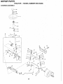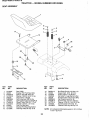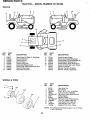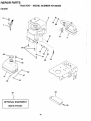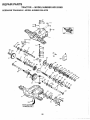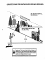
1
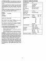
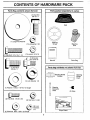
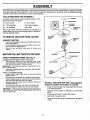
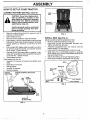
OWNER'S MANUAL
MODEL NO. HD125386
Lawn Tractor
Assembly
Operation
9
Customer Responsibilities
9
Service and Adjustments
Storage
Troubleshooting
Repair Parts
@
For Parts and Service, contact our authorized distributor: call 1-800-849-1
297
For Technical Assistance: call 1-800-829-5886
165412 04.24.98 RD
PRINTED IN U.S.A.
SAFETY RULES
.
Safe Operation Practices for Ride-On Mowers
a
IMPORTANT: THIS CUTTING MACHINE IS CAPABLE OF AMPUTATING HANDS AND FEET AND THROWING OBJECTS.
FAILURE TO OBSERVE THE FOLLOWING SAFETY INSTRUCTIONS COULD RESULT IN SERIOUS INJURY OR DEATH.
I.
a
*
e
*
GENERAL OPERATION
Read, understand, and follow all instructions in the manual
and on the machine before starting.
Only allow responsible adults, who are familiar with the instructions, to operate the machine.
Clear the area of objects such as rocks, toys, wire, etc.,
which could be picked up and thrown by the blade.
Be sure the area is clear of other people before mowing.
Stop machine if anyone enters the area.
Never carry passengers.
Do not mow in reverse unless absolute1 necessary.
Always look down and behind before and whi e backing.
Be aware of the mower discharge direction and do not point
it at anyone. Do not operate the mower without either the
entire grass catcher or the guard in place.
Slow down before turning.
Never leave a running machine unattended. Always turn
off blades, set parking brake, stop engine, and remove
keys before dismounting.
Turn off blades when not mowing.
Stop engine before removing grass catcher or unclogging
chute.
Mow only in daylight or good artificial light.
Do not operate the machine while under the influence of
alcohol or drugs.
Watch for traffic when operating near or crossing roadways.
Use extra care when loading or unloading the machine into
a trailer or truck.
Y
11. SLOPE OPERATION
Slopes are a major factor related to loss-of-control and
tipover accidents, which can result in severe injury or
death. All slopes require extra caution. If you cannot
back up the slope or if you feel uneasy on it, do not mow
it.
DO:
Mow up and down slopes, not across.
Remove obstacles such as rocks, tree limbs, etc.
Watch for holes, ruts, or bumps. Uneven terrain could
overturn the machine. Tall grass can hide obstacles.
Use slow speed. Choose a low gear so that you will not
have to stop or shift while on the slope.
Follow the manufacturer's recommendations for wheel
weights or counterweights to improve stability.
Use extra care with grass catchers or other attachments.
These can change the stability of the machine.
Keep all movement on the slopes slowand gradual. Do not
make sudden changes in speed or direction.
Avoid starting or stopping on a slope. If tires lose traction,
disengage the blades and proceed slowly straight down the
slope.
DO NOT:
Do not turn on slopes unless necessary, and then, turn
slowly and gradually downhill, if possible.
Do not mow near drop-offs, ditches, or embankments. The
mower could suddenly turn over if a wheel is over the edge
of a cliff or ditch, or if an edge caves in.
Do not mow on wet grass. Reduced traction could cause
sliding.
Do not try to stabilize the machine by putting your foot on
the ground.
Do not use grass catcher on steep slopes.
III. CHILDREN
~~~~i~
accidents can occur if the operator is not alert to
the presence of children. Children are often attracted to
the machine and the mowing
activity.Never assume that
children will remain where you last saw them.
* Keep children out of the mowing area and under the watch*
*
*
*
ful care of another responsible adult.
Be alert and turn machine off if children enter the area.
Before and when backing, look behind and down for small
children.
Never carry children. They ma fall off and be seriously
injured or interfere with safe mac ine operation.
Never all0w
childrenOperate the machine.
Use extra care when approaching blind corners, shrubs,
trees, or other objects that may obscure vision.
\
IV. SERVICE
* Use extra care in handling gasoline and other fuels. They
are flammable and vapors are explosive.
- Use only an approved container.
- Never remove gas cap or add fuel with the engine running. Allow engine to cool before refueling. Do not
smoke.
Never refuel the machine indoors.
- Never store the machine or fuel container inside where
there is an open flame, such as a water heater.
Never run a machine inside a closed area.
Keep nuts and bolts, especially blade attachment bolts,
tight and keep equipment in good condition.
Never tamper with safety devices. Check their proper operation regularly.
Keep machine free of grass, leaves, or other debris buildup. Clean oil or fuel spillage. Allow machine to cool before
storing.
Stop and inspect the equipment if you strike an object. .
Repair, if necessary, before restarting.
Never make adjustments or repairs with the engine running.
Grass catcher components are subject to wear, damage,
and deterioration, which could expose moving parts or
allow objects to be thrown. Frequently check components
and replace with manufacturer's recommended parts, when
necessary.
Mower blades are sharp and can cut. Wrap the blade(s) or
wear gloves, and use extra caution when servicing them.
Check brake operation frequently. Adjust and service as
-
Look for this symbol to point out imortant safety precautions. It means
dental starting when setting up, transporting, adjusting or maklng repairs.
A WARNING A
The en ine exhaust from this roduct contains c emicals known to the tate of California to cause cancer, birth defects, or other
reproductive harm.
I?
C
CONGRATULATIONS on your purchase of a New Tractor. It has been designed, engineered and manufactured
to give you the best possible dependability and performance.
Should you experience any problem you cannot easily
remedy, please contact your nearest authorized service
center/Department. We have competent, well-trained
technicians and the proper tools to service or repair this
tractor.
Please read and retain this manual. The instructions will
enable you to assemble and maintain your tractor properly. Always observe the "SAFETY RULES".
PRODUCT SPEClFlCMlONS
UNLEADED
SAE 30 (above 32°F)
SAE 5W-30 (below
OIL CAPACITY:
3.0 PINTS
Champion RJI 9LM
VALVE CLEARANCE:
DATE OF PLIRCHASE
INTAKE:
GROUND SPEED
THE MODEL AND SERIAL NUMBERS WILL BE
FOUND ON A PLATE UNDER THE SEAT.
YOU SHOULD RECORD BOTH SERIAL NUMBER
ND DATE OF PURCHASE AND KEEP IN A SAFE
TIRE PRESSURE:
CUSTOMER RESPONSIBILlflES
Read and observe the safety rules.
a
Follow a regular schedule in maintaining, caring for
and using your tractor.
Follow the instructions under "Customer Responsibilities" and "Storage" sections of this owner's manual.
WARNING: This tractor is equipped with an internal
combustion engine and should not be used on or near
any unimproved forest-covered, brush-covered or grasscovered land unless the engine's exhaust system is
equipped with a spark arrester meeting applicable local or
state laws (if any). If a spark arrester is used, it should be
maintained in effective working order by the operator.
In the state of California the above is required by law
(Section 4442 of the California Public Resources Code).
Other states may have similar laws. Federal laws apply
o n federal lands. A spark arrester for the muffler is available through your nearest Sears Authorized Service
Center/Department (See REPAIR PARTS section of this
manual).
FRONT: 14 PSI
REAR: 12 PSI
3 AMPS BAlTERY
5 AMPS HEADLIGHTS
CASE SIZE:
U1R
TABLE OF CONTENTS
SAFETY RULES ............................................................2
MAINTENANCE SCHEDULE ......................................14
PRODUCT SPECIFICATIONS ......................................3
SERVICE AND ADJUSTMENTS ............................19-24
CUSTOMER RESPONSIBILITIES ......................3, 14-18
STORAGE ....................................L.............................25
WARRANTY
ASSEMBLY
OPERATION
..................................................................4
................................................................6-8
..............................................................9-13
............................................26-27
..................................3047
................BACK COVER
TROUBLESHOOTING
REPAIR PARTS TRACTOR
PARTS ORDERING/SERVICE
-
LIMITED WARRANTY
The Manufacturer warrants to the original consumer purchaser that this product as manufactured is free from defects in materials and workmanship. For a period of two (2) years from date of purchase by the original consumer purchaser, we will repair or
replace, at our option, without charge for parts or labor incurred in replacing parts, any part which we find to be defective due to
materials or workmanship. This Warranty is subject to the following limitations and exclusions.
1. This warranty does not apply to the engine, other than AYP manufactured transaxle/transmission components, battery
(except as noted below) or components parts thereof. Please refer to the applicable manufacturer's warranty on these
2.
3.
4.
Transportation charges for the movement of any power equipment unit or attachment are the responsibility of the purchaser. Transportation charges for any parts submitted for replacement under this warranty must be paid by the purchaser
unless such return is requested by American Yard Products.
Battery Warranty: On products equipped with a Battery, we will replace, without charge to you, any battery which we find to
be defective in manufacture, during the first ninety (90) days of ownership. After ninety (90) days, we will exchange the
Battery, charging you 1/12 of the price of a new Battery for each full month from the date of the original sale. Battery must
be maintained in accordance with the instructions furnished.
The Warranty period for any products used for rental or commercial purposes is limited to 90 days from the date of original
5.
This Warranty applies only to products which have been properly assembled, adjusted, operated, and maintained in accordance with the instructions furnished. This Warranty does not apply to any product which has been subjected to alteration,
misuse, abuse, improper assembly or installation, delivery damage, or to normal wear of the product.
6. Exclusions: Excluded from this Warranty are belts, blades, blade adapters, normal wear, normal adjustments, standard
hardware and normal maintenance.
7. In the event you have a claim under this warranty, you must return the product to an authorized service dealer.
Should you have any unanswered questions concerning this Warranty, please contact:
American Yard Products
Service Department
P.O. Box 1687
Orangeburg, SC 29116 USA
In Canada contact:
American Yard Products
1580 Trinity Drive, Units 5-8
Mississauga, Ontario
L5T 1L6
giving the model number, serial number and date of purchase of your product and the name and address of the authorized dealer from whom it was purchased.
THIS WARRANTY DOES NOT APPLY TO INCIDENTALOR CONSEQUENTIAL DAMAGESAND ANY IMPLIED WARRANTIES
ARE LIMITED TO THE SAME TIME PERIODS STATED HEREIN FOR OUR EXPRESSED WARRANTIES. Some areas do not
allow the limitation of consequential damages or limitations of how long an implied Warranty may last, so the above limitations or
not apply to you. This Warranty gives you specific legal rights, and you may have other rights which vary from
CONTENTS OF HARDWARE PACK
(1) Large Flat Washer
(1) Lockwasher 318
(1) Locknut 511 6-18
(2) Hex Nuts 1/4-20
ASSEMBLY
Your new tractor has been assembled at the factory with exception of those parts left unassembled for shipping purposes.
To ensure safe and proper operation of your tractor all parts and hardware you assemble must' be tightened securely.
Use the correct tools as necessary to insure proper tightness.
TOOLS REQUIRED FOR ASSEMBLY
INSERT
A socket wrench set will make assembly easier. Standard wrench sizes are listed.
(1) 314" wrench
(1) 9/16" wrench
(2) 7/16" wrenches
Tire pressure gauge
(2) 112" wrenches
Utility knife
When right and left hand are mentioned in this manual, it
means when you are in the operating position (seated behind the steering wheel).
318 HEX BOLT
1
318 LOCK
WASHER
LARGE FLAT
WASHER
TO REMOVE TRACTOR FROM CARTON
STEERING
BOOT
UNPACK CARTON
0
*
Remove all accessible loose parts and parts cartons from
carton (See page 6).
Cut along lines on carton, from top to bottom, all four corners of carton and lay panels flat.
Check for any additional loose parts or cartons and
remove.
EXTENSION SHAFT
BEFORE ROLLING TRACTQR OFF SKlD
5/16 HEX BOLT
AmACH STEERING WHEEL (See Fig. 1)
ASSEMBLE EXTENSION SHAFT AND BOOT
*
Slide extension shaft onto lower steering shaft. Align
-'.
a
I
I
LOWER
STEERING
SHAFT
INSTALL STEERING WHEEL
Position front wheels of the tractor so they are pointing
straight forward.
Slide steering wheel adapter onto steering shaft extension.
*
Position steering wheel so cross bars are horizontal (left to
right) and slide inside boot and onto adapter..
Assemble large flat washer, 318 lock washer, 318 hex bolt
and tighten securely.
Snap steering wheel insert into center of steering wheel.
materials from tractor hood and grill.
~emove
IMPORTANT: CHECK FOR AND REMOVE ANY STAPLES IN
SKlD THAT MAY PUNCTURE TIRES WHERE TRACTOR IS
TO ROLL OFF SKID.
-i-. :2
5/16 LOCKNUT
mounting holes in extension and lower shafts and install
511 6 hex bolt and locknut. Tighten securely.
IMPORTANT: TIGHTEN BOLT AND NUT SECURELY TO 1822 FT. LBS TORQUE.
Place tabs of steering boot over tab slots in dash and push
down to secure.
0
FIG. 1
TO ROLL TRACTOR OFF SKID (See Operation
on and funetion of controls)
0
0
Press lift lever ~lunaerand raise attachment lift lever
to its highest position.
Release parking brake by depressing clutch/brake
pedal.
Place gearshift lever in neutral (N) position.
Roll tractor forward off skid.
Remove banding holding discharge guard up against
tractor.
ASSEMBLY
WOW TO SET UP YOUR TRACTOR
CONNECT BATTERY (See Figs. 2 and 3)
SEAT
PAN
BATTERY
BOX DOOR
Positive terminal must be connected
sparking from acci-
*
Remove cardboard packing from seat pan and lift
seat pan to raised position.
Open battery box door.
Remove terminal protective caps and discard.
If this battery is put into service after month and year
indicated on label (label located between terminals)
charge battery for minimum of one hour at 6-10
amps.
First connect RED battery cable to positive (+) terminal with hex bolt, flat washer, lock washer and hex
nut as shown. Tighten securely.
Connect BLACK grounding cable to negative (-) terminal with remaining hex bolt, flat washer, lock washer and hex nut. Tighten securely.
*
Close battery box door.
Open battery box door for:
lnspection for secure connections (to tighten hardware).
lnspection for corrosion.
Testingbattery.
Jumping (if required).
Periodic charging .
-
BLE
I
I
FIG. 3
INSTALL SEAT (See Fig. 4)
Adjust seat before tightening adjustment bolt.
Remove cardboard packing on seat pan.
Place seat on pan and assemble shoulder bolt.
Tighten shoulder bolt securely.
Assemble adjustment bolt, lock washer and flat
washer loosely. Do not tighten.
Lower seat into operating position and sit on seat.
Slide seat until a comfortable position is reached
which allows you to press clutchlbrake pedal all the
way down (See Fig. 8).
Get off seat without moving its adjusted position.
Raise seat and tighten adjustment bolt securely.
CAPS
HEX
\
LOCK
WASHER
I
FLAT WASHER
FLAT
FIG. 4
NEGATI~E
(BLACK) CABLE
FIG. 2
ASSEMBLY
CHECK TIRE PRESSURE
The tires on your tractor were overinflated at the factory
for shipping purposes. Correct tire pressure is important
for best cutting performance.
Reduce tire pressure to PSI shown in "PRODUCT
SPECIFICATIONS" on page 3 of this manual.
CHECK DECK LEVELNESS
For best cutting results, mower housing should be properly leveled. See "TO LEVEL MOWER HOUSING" in the
Service and Adjustments section of this manual.
CHECK FOR PROPER POSITION OF ALL
BELTS
See the figures that are shown for replacing motion and
mower blade drive belts in the Service and Adjustments
section of this manual, Verify that the belts are routed
correctly.
CHECK BRAKE SYSTEM
After you learn how to operate your tractor, check to see
that the brake is properly adjusted. See "TO ADJUST
BRAKE" in the Service and Adjustments section of this
manual.
J CHECKLIST
BEFORE YOU OPERATE AND ENJOY YOUR NEW
TRACTOR, WE WISH TO ASSURE THAT YOU RECEIVE THE BEST PERFORMANCE AND SATISFACTION FROM THIS QUALITY PRODUCT.
PLEASE REVIEW THE FOLLOWING CHECKLIST
J All assembly instructions have been completed.
J No remaining loose parts in carton.
J Battery is properly prepared and charged. (Minimum
1 hour at 6 amps).
J Seat is adjusted comfortably and tightened securely.
J All tires are properly inflated. (For shipping purposes,
the tires were overinflated at the factory).
J Be sure mower deck is properly leveled side-tosidelfront-to-rearfor best cutting results. (Tires must
be properly inflated for leveling).
J Check mower and drive belts. Be sure they are routed properly around pulleys and inside all belt keepers.
J Check wiring. See that all connections are still
secure and wires are properly clamped.
WHILE LEARNING HOW TO USE YOUR TRACTOR.
PAY EXTRA ATTENTION TO THE FOLLOWING IMPOR:
TANT ITEMS:
J Engine oil is at proper level.
J Fuel tank is filled with fresh, clean, regular unleaded
gasoline.
J Become familiar with all controls - their location and
function. Operate them before you start the engine.
J Be sure brake system is in safe operating condition.
.
These symbols may appear on your tractor or in literature supplied with the product. Learn and understand their mean-
ing.
BAlTERY
CAUTION OR
WARNING
REVERSE
FORWARD
FAST
ENGINE ON
ENGINE OFF
OIL PRESSURE
LIGHTS ON
OVER TEMP
LIGHT
FUEL
CHOKE
MOWER HEIGHT
PARKING BRAKE
LOCKED
UNLOCKED
R N H L
AlTACHMENT
CLUTCH ENGAGED
IGNITION
REVERSE
NEUTRAL
ATTACHMENT
CLUTCH DISENGAGED
DANGER, KEEP HANDS AND FEET AWAY
HIGH
LOW
SLOW
MOWER LIFT
8I
8
PARKING BRAKE
KEEP AREA CLEAR
SLOPE HAZARDS
(SEE SAFETY RULES SECTION)
FREE WHEEL.
(Automatic Models only)
OPERATION
KNOW YOUR TRACTOR
READ 'THIS OWNER'S MANUAL AND SAFETY RULES BEFORE OPERATING YOUR TRACTOR
Compare the illustrations with your tractor to familiarize yourself with the locations of various controls and adjustments.
Save this manual for future reference.
i
LIGHT SWITCH PQSITIIQN
I
LEVER
I
FIG. 5
Our tractors conform to the safety standards of the American National Standards Institute.
ATTACHMENT CLUTCH LEVER: Used to engage the
mower blades, or other attachments mounted to your
tractor.
LIGHT SWITCH: Turns the headlights on and off.
THROTTLWCHOKE CONTROL: Used for starting and
controlling engine speed.
CLUTCHIBRAKE PEDAL: Used for declutching and
braking the tractor and starting the engine.
PARKING BRAKE: Locks clutchlbrake pedal into the
brake position.
GEARSHIFT LEVER: Selects the speed and direction of
tractor.
AnACHMENT LIFT LEVER: Used to raise, lower and
adjust the mower deck or other attachments mounted to
your tractor.
LIFT LEVER PLUNGER: Used to release attachment lift
lever when changing its position.
IGNITION SWITCH: Used for starting and stopping the
engine.
I
I
I
,
-
OPERATION
HOW TO USE YOUR TRACTOR
TO SET PARKING BRAKE (See Fig. 6)
Your tractor is equipped with an operator presence sensing
switch. When engine is running, any attempt by the operator to
leave the seat without first setting the parking brake will shut off
the engine.
*
Depress clutchlbrake pedal into full "BRAKE position
and hold.
*
Place parking brake lever in "ENGAGED" position
and release pressure from clutchlbrake pedal. Pedal
should remain in "BRAKE" position. Make sure parking brake will hold tractor secure.
"DISENGAGED"
PARKING BRAKE
TO USE THROTLE CONTROL (See Fig. 6)
Always operate engine at full throttle.
* Operating engine at less than full throttle reduces the bat*
tery charging rate.
Full throttle offers the best bagging and mower performance.
TO MOVE FORWARD AND BACKWARD
(See Fig. 6)
The direction and speed of movement is controlled by
the gearshift lever.
Start tractor with clutchlbrake pedal depressed and
gearshift lever in neutral (N) position.
* Move gearshift lever io desired position.
* Slowly release clutchtbrake pedal to start movement.
IMPORTANT: BRING TRACTOR TO A COMPLETE STOP
BEFORE SHIFTING OR CHANGING GEARS. FAILURE TO
DO SO WILL SHORTEN THE USEFUL LIFE OF YOUR
TRANSAXLE.
TO ADJUST MOWER CUTTING HEIGHT
(See Fig. 5)
FIG. 6
STOPPING (See Fig. 6)
MOWER BLADES Move attachment clutch lever to "DISENGAGED" position.
GROUND DRIVE *
Depress clutchlbrake pedal into full "BRAKE" position.
Move gearshift lever to neutral (N) position.
ENGINE *
Move throttle control to slow position.
NOTE: Failure to move throttle control to slow position
and allowing engine to idle before stopping may cause
engine to "backfire".
Turn ignition key to "OFF position and remove key. Always
remove key when leaving tractor to prevent unauthorized
use.
Never use choke to stop engine.
NOTE: Under certain conditions when tractor is standing
idle with the engine running, hot engine exhaust gases
may cause "browning" of grass. To eliminate this possibility, always stop engine when stopping tractor on grass
areas.
The position of the attachment lift lever determines the
cutting height.
* Graspliftlever.
* Press plunger with thumb and move lever to desired position.
The cutting height range is approximately 1-112 to 4".
The heights are measured from the ground to the blade
tip with the engine not running. These heights are
approximate and may vary depending upon soil conditions, height of grass and types of grass being mowed.
* The average lawn should be cut to approximately 2-112
*
inches during the cool season and to over 3 inches during
hot months. For healthier and better looking lawns, mow
often and after moderate growth.
For best cutting performance, grass over 6 inches in height
should be mowed twice. Make the first cut relatively high;
the second to desired height.
--
-
TO OPERATE MOWER (See Fig. 7 )
Your tractor is equipped with an operator presence sensing switch. Any attempt by the operator to leave the seat
with the engine running and the attachment clutch
engaged will shut off the engine.
Select desired height of cut.
Start mower blades by engaging attachment clutch
control.
TO STOP MOWER BLADES - disengage attachment
clutch control.
*
To restart movement, slowly release parking brake
and clutchlbrake pedal.
Make all turns slowly.
TO TRANSPORT
Raise attachment liR to highest position with attachment lift
control.
When pushing or towing your tractor, be sure gearshift
lever is in neutral (N) pos~tion.
Do not push or tow tractor at more than five (5) MPH.
NOTE: To protect hood from damage when transporting
your tractor on a truck or a trailer, be sure hood is closed
and secured to tractor. Use an appropriate means of
tying hood to tractor (rope, cord, etc.).
BEFORE STARTING THE ENGINE
CHECK ENGINE OIL LEVEL (See Fig. 12)
*
*
*
*
The engine in your tractor has been shipped, from the factory, already filled with summer weight oil.
Check engine oil with tractor on level ground.
Remove oil fill captdipstick and wipe clean, reinsert the dipstick and screw cap tight, wait for a few seconds, remove
and read oil level. If necessary, add oil until "FULL" mark
on dipstick is reached. Do not overfill.
For cold weather operation you should change oil for easier starting (See "OIL ViSCOSlTY CHART" in the Customer
Responsibilities section of this manual).
To change engine oil, see the Customer Responsibilities
section in this manual.
ADD GASOLINE
Fill fuel tank. Use fresh, clean, regular unleaded
gasoline with a minimum of 87 octane. (Use of leaded gasoline will increase carbon and lead oxide
deposits and reduce valve life). Do not mix oil with
gasoline. Purchase fuel in quantities that can be
used within 30 days to assure fuel freshness.
IMPORTANT: WHEN OPERATING IN TEMPERATURES
BELOW 32"FI0°C\. USE FRESH. CLEAN WINTER GRADE
GASOI-INE T'O H'ELP INSURE 'GOOD COLD WEATHER
STARTING.
TO OPERATE ON HILLS
Choose the slowest speed before starting up or
down hills.
Avoid stopping or changing speed on hills.
If slowing is necessary, move throttle control lever to
slower position.
If stopping is absolutely necessary, push clutchhrake
pedal quickly to brake position and engage parking
brake.
Move gearshift lever to 1st gear. Be sure you have
allowed room for tractor to roll siightly as you restart
movement.
WARNING: Experience indicates that alcohol blended
fuels (called gasohol or using ethanol or methanol) can
attract moisture which leads to separation and formation
of acids during storage. Acidic gas can damage the fuel
system of an engine while in storage. To avoid engine
problems, the fuel system should be emptied before storage of 30 days or longer. Drain the gas tank, start the
engine and let it run until the fuel lines and carburetor are
empty. Use fresh fuel next season. See Storage Instructions for additional information. Never use engine or carburetor cleaner products in the fuel tank or permanent
damage may occur.
CAUTION: Fill to bottom of gas tank
filler neck. Do not overfill. Wipe off
any spilled oil or fuel. Do no2 store,
spill or use gasoline near an open
flame.
'
OPERATION
TO START ENGINE (See Fig. 6)
When starting the engine for the first time or if the engine
has run out of fuel, it will take extra cranking time to move
fuel from the tank to the engine.
Sit on seat in operating position, depress clutchlbrake
pedal and set parking brake.
*
Place gear shift lever in neutral (N) position.
Move attachment clutch to "DISENGAGED" position.
*
Move throttle control to choke position.
NOTE: Before starting, read the warm and cold starting
procedures below.
Insert key into ignition and turn key clockwise to "START"
position and release key as soon as engine starts. Do not
run starter continuously for more than fifteen seconds per
minute. If the engine does not start after several attempts,
move throttle control to fast position, wait a few minutes
and try again. If engine still does not start, move the throttle control back to the choke position and retry.
MOWING TIPS
*
*
*
8
*
WARM WEATHER STARTING (50" F and above)
*
When engine starts, move the throttle control to the fast
position.
The attachments and ground drive can now be used. If the
engine does not accept the load, restart the engine and
allow it to warm up for one minute using the choke as
described above.
COLD WEATHER STARTING ( 50"F and below)
When engine starts, allow engine to run with the throttle
control in the choke position until the engine runs roughly,
then move throttle control to fast position. This may require
an engine warm-up period f r ~ m
several seconds to several
minutes, depending on the temperature.
The attachments can also be used during the engine warmup period.
0
*
Tire chains cannot be used when the mower housing is
attached to tractor.
Mower should be properly leveled for best mowing performance. See "TO LEVEL MOWER HOUSING" in the
Service and Adjustments section of this manual.
Use the runner on the right hand side of mower as a guide.
The blade cuts approximately an inch outside the runner
(See Fig. 7).
The left hand side of mower should be used for trimming.
Drive so that clippings are discharged onto the area that
has been cut. Have the cut area to the right of the
machine. This will result in a more even distribution of clippings and more uniform cutting.
When mowing large areas, start by turning to the right so
that clippings will discharge away from shrubs, fences, driveways, etc. After one or two rounds, mow in the opposite
direction making left hand turns until finished (See Fig. 8).
If grass is extremely tall, it should be mowed twice to
reduce load and possible fire hazard from dried clippings.
Make first cut relatively high; the second to the desired
,
height.
Do not mow grass when it is wet. Wet grass will plug
mower and leave undesirable clumps. Allow grass to dry
before mowing.
Always operate engine at full throttle when mowing to
assure better mowing performance and proper discharge of
material. Regulate ground speed by selecting a low
enough gear to give the mower cutting performance as well
as the quality of cut desired.
When operating attachments, select a ground speed that
will suit the terrain and give best performance of the attachment being used.
NOTE: If at a high altitude (above 3000 feet) or in cold
temperatures (below 32 F) the carburetor fuel mixture
may need to be adjusted for best engine performance.
See 'TO ADJUST CARBURETOR" in the Service and
Adjustments section of this manual.
FIG. 8
CUSTOMER RESPONSIBIL
I
NANCE SCHEDULE
I
Check Brake Operation
1
I
SharpenIReplace Mower Blades
d
4
Lubrication Chart
4
I
I
I
1
I
I
I
I
1
-
d
Check Battery Level
Clean Battery and TerminalsIRecharge
(
Check Transaxle Cooling
Adjust Blade Belt(s) Tension
Adjust Motion Drive Belt@) Tension
Check Engine Oil Level
Chanae Enaine Oil
/
Clean Air Filter
Clean Air Screen
Inspect MufflerISpark Arrester
I Replace Oil Filter (If equipped)
Clean Engine Cooling Fins
Replace Spark Plug
Replace Air Filter Paper Cartridge
R e ~ l a c eFuel Filter
1 -Change more often when operating under a heavy load or in high zmbient temperatures. 5 - If equipped with adjustable system.
2 - Service more often when operating in dirty or dusty conditions.
6 - Not required if equipped with maintenance-free battery.
3 If equipped with oil filter, change oil every 50 hours.
7 -Tighten front axle pivot bolt to 35 ft.-lbs. maximum.
GENERAL RECOMMENDATIONS
The warranty on this tractor does not cover items that
have been subjected to operator abuse or negligence. To
receive full value from the warranty, operator must maintain tractor as instructed in this manual.
Some adiustments will need to be made periodically to
properly maintain your tractor.
All adjustments in the Service and Adjustments section of
this manual should be checked at least once each season.
Once a year you should replace the spark plug, clean
or replace air filter, and check blades and belts for
wear. A new spark plug and clean air filter assure
proper air-fuel mixture and help your engine run better and last longer.
LUBRICKTION CHART
SPINDLE ZERK @
FRONT WHEEL @
BEARING ZERK
aATTACHMENT
CLUTCH
PIVOT(S)
BEFORE EACH USE
*
I
aSAE 30 OR 10W30--_-MOTOR OIL
I.
Check engine oil level.
Check brake operation.
Check tire pressure.
Check for loose fasteners.
:
--_---
!
I
@ GENERAL PURPOSE GREASE
@ REFER TO CUSTOMER RESPONSIBILITIES"ENGINE SECTION
14
IMPORTANT: DO NOT OIL OR GREASE THE PIVOT POINTS
WHICH HAVE SPECIAL NYLON BEARINGS. VISCOUS LUBRICANTS WlLL ATTRACT DUST AND DIRT THAT WlLL SHORTEN THE
LIFE OF THE SELF-LUBRICATING BEARINGS. IF YOU FEEL THEY
MUST BE LUBRICATED. USE ONLY A DRY, POWDERED GRAPHITE
TYPE LUBRICANT SPARINGLY.
CUSTOMER RESPONS
TRACTOR
Always observe safety rules when performing any maintenance.
MANDREL
ASSEMBLY
TRAILING EDGE
I
STAR
\
BRAKE OPERATION
If tractor requires more than six (6) feet stopping distance
at high speed in highest gear, then brake must be adjusted. (See 'TO ADJUST BRAKE in the Service and Adjustments section of this manual).
TIRES
Maintain proper air pressure in all tires (See "PRODUCT SPECIFICATIONS" on page 3 of this manual).
Keep tires free of gasoline, oil, or insect control
chemicals which can harm rubber.
Avoid stumps, stones, deep ruts, sharp objects and
other hazards that may cause tire damage.
NOTE: To seal tire punctures and prevent flat tires due to
slow leaks, tire sealant may be purchased from your local
parts dealer. Tire sealant also prevents tire dry rot and
corrosion.
BLADE CARE
For best results mower blades must be kept sharp. Replace bent or damaged blades.
BLADE REMOVAL (See Fig. 9)
*
Raise mower to highest position to allow access to
blades.
Remove hex bolt, lock washer and flat washer securing blade.
Install new or resharpened blade with trailing edge up
towards deck as shown.
LOCK
I
'A GRADE 8 HEAT TREATED BOLT CAN BE
IDENTIFIED BY SIX LINES ON THE BOLT HEAD.
I
FIG. 9
TO SHARPEN BLADE (See Fig. 10)
Care should be taken to keep the blade balanced. An
unbalanced blade will cause excessive vibration and
eventual damage to mower and engine.
9
The blade can be sharpened with a file or on a grinding
wheel. Do not attempt to sharpen while on the mower.
To check blade balance, you will need a 518 diameter steel
bolt, pin, or a cone balancer. (When using a cone balancer,
follow the instructions supplied with balancer).
Slide blade on to an unthreaded portion of the steel bolt or
pin and hold the bolt or pin parallel with the ground. If
blade is balanced, it should remain in a horizontal position.
If either end of the blade moves downward, sharpen the
heavy end until the blade is balanced.
NOTE: Do not use a nail for balancing blade. The lobes
of the center hole may appear to be centered, but are not.
IMPORTANT: TO ENSURE PROPER ASSEMBLY, CENTER
HOLE IN BLADE MUST ALIGN WITH STAR ON MANDREL
ASSEMBLY.
Reassemble hex bolt, lock washer and flat washer in
exact order as shown.
Tighten bolt securely (27-35 Ft. Lbs. torque).
IMPORTANT: BLADE BOLT IS GRADE 8 HEAT TREATED.
NOTE: We do not recommend sharpening blade - but if
you do, be sure the blade is balanced.
518" BOLT
OR PIN
ADE
FIG. 10
CUSTOMER RESPONSIBILITIES
BArrERY
Your tractor has a battery charging system which is sufficient for normal use. However, periodic charging of the
battery with an automotive charger will extend its life.
Keep battery and terminals clean.
* Keep battery bolts tight.
r
Keep small vent holes open.
* Recharge at 6-10 amperes for 1 hour.
TO CLEAN BASTERY AND TERMINALS
Corrosion and dirt on the battery and terminals can cause
the battery to "leak" power.
Open battery box door.
Disconnect BLACK battery cable first then RED battery cable and remove battery from tractor.
* Rinse the battery with plain water and dry.
* Clean terminals and battery cable ends with wire
brush until bright.
Coat terminals with grease or petroleum jelly.
Reinstall battery (See "CONNECT BATTERY" in the
Assembly section of this manual).
NOTE: Although multi-viscosity oils (5W30, 10W30 etc.)
improve starting in cold weather, these multi-viscosity oils
will result in increased oil consumption when used above
32°F. Check your engine oil level more frequently to
avoid possible engine damage from running low on oil.
Change the oil after every 25 hours of operation or at
least once a year if the tractor is not used for 25 hours in
one year.
Check the crankcase oil level before starting the engine
and after each eight (8) hours of operation. Tighten oil fill
capldipstick securely each time you check the oil level.
TO CHANGE ENGINE OIL (See Figs. 11 and 12)
Determine temperature range expected before oil
change. All oil must meet API service classification SF,
SG or SH.
*
*
V-BELTS
Check V-belts for deterioration and wear after 100 hours
of operation and replace if necessary. The belts are not
adjustable. Replace belts if they begin to slip from wear.
Be sure tractor is on level surface.
Oil will drain more freely when warm.
Catch oil in a suitable container.
Remove oil fill capldipstick. Be careful not to allow dirt to
enter the engine when changing oil.
Remove drain plug.
After oil has drained completely, replace oil drain plug and
tighten securely.
Refill engine with oil through oil fill dipstick tube. Pour slowly. Do not overfill. For approximate capacity see "PRODUCT SPECIFICATIONSnon page 3 of this manual.
Use gauge on oil fill capldipstick for checking level. Be
sure dipstick cap is tightened securely for accurate reading.
Keep oil at "FULLnline on dipstick.
TRANSAXLE COOLING
Keep transaxle free from build-up of dirt and chaff which
can restrict cooling.
ENGINE
LUBRICATION
Only use high quality detergent oil rated with API service
classification SF, SG or SH. Select the oil's SAE viscosity grade according to your expected operating temperature.
FIG. 12
FIG. 11
CUSTOMER RESPONSIB
AIR FILTER (See Fig. 13)
CLEAN AIR SCREEN (See Fig. 14)
Your engine will not run properly using a dirty air filter.
Glean the foam pre-cleaner after every 25 hours of operation or every season. Service paper cartridge every 100
hours of operation or every season, whichever occurs
first.
Service air cleaner more often under dusty conditions.
0
Remove knob(s) and cover.
TO SERVICE PRE-CLEANER
Slide foam pre-cleaner off cartridge.
Wash it in liquid detergent and water.
Squeeze it dry in a clean cloth.
Saturate it in engine oil. Wrap it in clean, absorbent
cloth and squeeze to remove excess oil.
If very dirty or damaged, replace pre-cleaner.
Reinstall pre-cleaner over cartridge.
Reinstall cover and secure with knob(s).
TO SERVICE CAR-TRIDGE
Remove cartridge nut.
Carefully remove cartridge to prevent debris from entering carburetor. Clean base carefully to prevent
debris from entering carburetor.
Clean cartridge by tapping gently on flat surface. If
very dirty or damaged, replace cartridge.
Reinstall cartridge, nut, precleaner, cover and secure
with knob(s).
Air screen must be kept free of dirt and chaff to prevent
engine damage from overheating. Clean with a wire
brush or compressed air to remove dirt and stubborn
dried gum fib&s.
ENGINE COOLING FINS (See Fig. 14)
Remove any dust, dirt or oil from engine cooling fins to
prevent engine damage from overheating.
Remove screws from blower housing and lift housing
and dipstick tube assembly off engine.
Cover oil fill opening to prevent entry of dirt.
Use compressed air or stiff bristle brush to thoroughly clean engine cooling fins.
To reassemble, reverse above procedure.
IMPORTANT:
PETROLEUM SOLVENTS, SUCH AS
KEROSENE, ARE NOT TO BE USED TO CLEAN THE CARTRIDGE. THEY MAY CAUSE DETERIORATION OF THE
CARTRIDGE. DO NOT OIL CARTRIDGE. DO NOT USE
PRESSURIZED AIR TO CLEAN OR DRY CARTRIDGE.
FIG. 14
FOAM
PRE-CLEANER
PAPER
CARTRIDGE
FIG. 13
CUSTOMER RESPONSIBILITIES
MUFFLER
Inspect and replace corroded muffler and spark arrester
(if equipped) as it could create a fire hazard andlor damage.
SPARK PLUGS
Replace spark plugs at the beginning of each mowing
season or after every 100 hours of operation, whichever
occurs first. Spark plug type and gap setting are shown
in "PRODUCT SPECIFICATIONS" on page 3 of this manual.
FIG. 15
IN-LINE FUEL FILTER (See Fig. 15)
The fuel filter should be replaced once each season. If
fuel filter becomes clogged, obstructing fuel flow to carburetor, replacement is required.
With engine cool, remove filter and plug fuel line sections.
Place new fuel filter in position in fuel line with arrow
pointing towards carburetor.
Be sure there are no fuel line leaks and clamps are
properly positioned.
Immediately wipe up any spilled gasoline.
CLEANING
Clean engine, battery, seat, finish, etc. of all foreign
matter.
Keep finished surfaces and wheels free of all gasoline, oil, etc.
Protect painted surfaces with automotive type wax.
We do not recommend using a garden hose to clean your
tractor unless the electrical system, muffler, air filter and
carburetor are covered to keep water out. Water in
engine can result in a shortened engine life.
~
SERVICE AND ADJUSTMENTS
Depress clutchbrake pedal fully and set parking brake.
Place gearshift lever in neutral (N) position.
Place attachment clutch in "DISENGAGED" position.
Turn ignition key "OFF" and remove key.
Make sure the blades and all moving parts have completely stopped.
ct spark plug wire from spark plug and place wire where it cannot come in contact
TO REMOVE MOWER (See Fig. 16)
Mower will be easier to remove from the right side of tractor.
Place attachment clutch in "DISENGAGED position.
Move attachment lift lever forward to lower mower to
its lowest position.
Roll belt off engine pulley.
Disconnect clutch rod from clutch lever by removing
retainer spring.
Disconnect anti-sway bar from chassis bracket by removing retainer spring.
Disconnect suspension arms from rear deck brackets
by removing retainer springs.
Disconnect front links from deck by removing retainer
springs.
Raise lift lever to raise suspension arms. Slide mower
out from under tractor.
RETAINER SPRING
IMPORTANT: IF AN ATTACHMENT OTHER THAN THE
MOWER DECK IS TO BE MOUNTED ON THE TRACTOR,
REMOVE THE FRONT LINKS.
-
TO INSTALL MOWER (See Fig. 16)
-
Raise attachment lift lever to its highest position.
Slide mower under tractor with discharge guard to
right side of tractor.
Lower lift lever to its lowest position.
Install mower in reverse order of removal instructions.
ANTI-SWAY B
FIG. 16
SERVICE AND ADJUSTMENTS
FRONT-TO-BACKADJUSTMENT,(See Figs. 19 and 20)
TO
- - LEVEL MOWER HOUSING
-
Adjust the mower while tractor is parked on level ground
or driveway. Make sure tires are properly inflated (See
"'PRODUCT SPECIFICATIONS" on page 3 of this manual). If tires are over or underinflated, YOU will not properly adjust your mower.
SIDE-TO-SIDE ADJUSTMENT (See Figs. 17 and 18)
Raise mower to its highest position.
At the midpoint of both sides of mower, measure
height from bottom edge of mower to ground.
Distance "A" on both sides of mower should be the
same or within 114" of each other.
* If adjustment is necessary, make adjustment on one
side of mower only.
To raise one side of mower, tighten lift link adjustment
nut on that side.
To lower one side of mower, loosen lift link adjustment nut on that side.
NOTE: Three full turns of adjustment nut will change
mower height about 118".
Recheck measurements after adjusting.
OF MOWER TO
-.a
IMPORTANT: DECK MUST BE LEVEL SIDE-TO-SIDE. IF
THE FOLLOWING FRONT-TO-BACK ADJUSTMENT 1s NEcESSARY, BE SURE TO ADJUST BOTH FRONT LINKS
EQUALLY SO MOWER WILL STAY LEVEL SIDE-TO-SIDE.
To obtain the best cutting results, the mower housing
should be adjusted so that the front is approximately 118"
to 112" lower than the rear when the mower is in its highest position.
Check adjustment on right side of tractor. Measure distance "D" directly in front and behind the mandrel at bottom edge of mower housing as shown.
Before making any necessary adjustments, check
that both front links are equal in length. Both links
should be approximately 10-318".
If links are not equal in length, adjust one link to same
length as other link.
To lower front of mower loosen nut "En on both front
links an equal number of turns.
* When distance "D" is 118" to 112" lower at front than
rear, tighten nuts "F" against trunnion on both front
links.
* To raise front of mower, loosen nut "F" from trunnion
on both front links. Tighten nut "En on both front links
an equal number of turns.
When distance "D" is 118" to 112" lower at front than
rear, tighten nut "F" against trunnion on both front
links.
Recheck side-to-side adjustment.
I
a-
SUSPENSION
FIG. 19
FIG. 18
I
FRONTLINKS
TRUNNION
FIG. 20
I
SERVICE AND ADJUSTMENTS
TO REPLACE MOWER BLADE DRIVE BELT
(See Fig. 21)
T h e mower blade drive belt may be replaced without
tools. Park the tractor on level surface. Engage parking
brake.
BELT REMOVAL * Place attachment clutch in "DISENGAGED" position.
*
Move attachment lift lever forward to lower mower to
its lowest position.
Roll belt off engine pulley.
Disconnect R.H. suspension arm from rear deck
bracket by removing retainer spring.
* Work belt off both mandrel pulleys and idler pulleys.
Pull belt away from mower.
BELT INSTALLATION Install new belt in reverse order of removal.
0
Make sure belt is in all pulley grooves and inside all
belt guides.
-
-
1
I
MANDREL
R.H. SUSPENSION ARM
ENGINE PULLEY
FIG. 22
TO REPLACE MOTION DRIVE BELT
(See Fig. 23)
Park the tractor on level surface. Engage parking brake.
For assistance, there is a belt installation guide decal on
bottom side of left footrest.
Remove mower (See '70REMOVE MOWER" in this
section of this manual.)
Remove belt from stationary idler and clutching idler.
Pull belt slack toward rear of tractor. Remove belt
upwards from transaxle pulley by deflecting belt
keepers.
Pull belt toward front of tractor and remove downwards from around engine pulley.
Install new belt by reversing above procedure.
YS
SPRING
a
I
FIG. 21
TO ADJUST BRAKE (See Fig. 22)
Your tractor is equipped with an adjustable brake system
which is mounted on the right side of the transaxle.
If tractor requires more than six (6) feet stopping distance
at high speed in highest gear, then brake must be adjusted.
* Depress clutch/brake pedal and engage parking
brake.
* Measure distance between brake operating arm and
nut "A" on brake rod.
If distance is other than 1-1/2", loosen jam nut and
turn nut "A" until distance becomes 1-1/2". Retighten
jam nut against nut "A".
*
Road test tractor for proper stopping distance as stated above. Readjust if necessary. If stopping distance is still greater than six (6) feet in highest gear,
further maintenance is necessary. Contact your
nearest authorized service center.
STATIONARY
FIG. 23
SERVICE AND ADJUSTMENTS
TO ADJUST S'FEERING WHEEL ALIGNMENT
If steering wheel crossbars are not horizontal (left to right)
when wheels are positioned straight forward, remove
steering wheel and reassemble per instructions in the
Assembly section of this manual.
FRONT WHEEL TOE-INICAMBER
The front wheel toe-in and camber are not adjustable on
your tractor. If damage has occurred to affect the front
wheel toe-in or camber, contact your nearest authorized
service center.
TO REMOVE WHEEL FOR REPAIRS
(See Fig. 24)
Block up axle securely.
Remove axle cover, retaining ring and washers to
allow wheel removal (rear wheel contains a square
key Do not lose).
Repair tire and reassemble.
On rear wheels only: align grooves in rear wheel hub
and axle. Insert square key.
Replace washers and snap retaining ring securely in
axle groove,
Replace axle cover.
NOTE: To seal tire punctures and prevent flat tires due to
slow leaks, tire sealant may be purchased from your local
parts dealer. Tire sealant also prevents tire dry rot and
corrosion.
-
AXLE COVER
SQUARE KEY
(REAR WHEEL ONLY)
FIG. 24
SERVICE AND ADJUSTMENTS
T0,START ENGINE WITH A WEAK BAlTERY
(See Fig. 25)
TO REPLACE HEADLIGHT BULB
*
ate explosive gases. Keep sparks,
flame and smoking materials away
from batteries. Always wear eye protection when around batteries.
If your battery is too weak to start the engine, it should be
emergency
recharged- If rumper cables* are used
starting, follow this procedure:
IMPORTANT: 'OUR
IS EQU'PPED
A l2
VOLT NEGATIVE GROUNDED SYSTEM. THE OTHER VEHICLE MUST ALSO BE A 12 VOLT NEGATIVE GROUNDED
SYSTEM. DO NOT USE YOUR TRACTOR BATTERY TO
START OTHER VEHICLES.
TO ATTACH JUMPER CABLES -
=
Connect each end of the RED cable to the POSITIVE (+)
terminal of each battery, taking care not to short against
chassis.
Connect one end of the BLACK cable to the NEGATIVE (-)
terminal of fully charged battety.
Connect the other end of the BLACK cable to good CHASSIS GROLIND, away from fuel tank and battery.
TO REMOVE CABLES, REVERSE ORDER BLACK cable first from chassis and then from the fully
charged battery.
RED cable last from both batteries.
a
Raise hood.
Pull bulb holder out of the hole in the backside of the
grill.
Replace bulb in holder and push bulb holder securely back into the hole in the backside of the grill.
Close hood.
INTERLOCKS AND RELAYS
Loose or damaged wiring may cause your tractor to run
~oorlv,s t o
it from startina.
. ~runninn.
-. or prevent
.
Check wiring. See electrical wiring
in Repair
Parts section of this manual.
;
a.
TO REPLACE FUSE
Replace with 30 amp automotive-type plug-in fuse. The
fuse holder is located behind the dash.
TO REMOVE HOOD AND GRILL ASSEMBLY
(See Fig. 26)
Raise hood.
Unsnap headlight wire connector.
Stand in front of tractor. Grasp hood at sides, tilt
toward engine and lift off of tractor.
To replace, reverse above procedure.
FIG. 26
FIG. 25
SERVICE AND ADJUSTMENTS
TO ADJUST CARBURETOR The carburetor has
ENGINE
TO ADJUST THROTTLE CONTROL CABLE
(See Fig. 27)
The throttle control has been preset at the factory and adjustment should not be necessary. Check adjustment as
described below before loosening cable. If adjustment is
necessary, proceed as follows:
a
a
With engine not running, move throttle control lever from
slow to choke position. Slowly move lever from choke to
fast position.
Check that holes "A" in overnor control lever and hole in
governor plate line-up. I holes "An are not ali ned, loosen
clamp screw and move throttle cable unti holes are
aligned. Tighten clamp screw securely.
?
B
GOVERNOR
CONTROL PLATE
FIG. 27
been preset at the factory and adjustment should not be
necessary. However, minor adjustment may be required
to compensate for differences in fuel, temperature, altitude or load. If the carburetor does need adjustment, see
engine manual.
IMPORTANT: NEVER TAMPER WITH THE ENGINE GOVERNOR, WHICH IS FACTORY SET FOR PROPER ENGINE
SPEED. OVERSPEEDING THE ENGINE ABOVE THE FACTORY HlGH SPEED SETTING CAN B E DANGEROUS. IF
YOU THINKTHE ENGINE-GOVERNEDHlGH SPEED NEEDS
ADJUSTING. CONTACT YOUR NEAREST AUTHORIZED
SERVICE CENTERIDEPARTMENT, WHICH HAS PROPER
EQUIPMENT AND EXPERIENCE TO MAKE ANY NECESSARY ADJUSTMENTS.
STORAGE
Immediately prepare your tractor for storage at the end of
the season or if the tractor will not be used for 30 days or
more.
TRACTOR
Remove mower from tractor for winter storage. When
mower is to be stored for a period of time, clean it thoroughly, remove all dirt, grease, leaves, etc. Store in a
clean, dry area.
Clean entire tractor (See "CLEANING" in the
Customer Responsibilities section of this manual).
lnspect and replace belts, if necessary (See belt replacement instructions in the Service and
Adjustments section of this manual).
Lubricate as shown in the Customer Responsibilities
section of this manual.
Be sure that all nuts, bolts and screws are securely
fastened. lnspect moving parts for damage, breakage and wear. Replace if necessary.
Touch up all rusted or chipped paint surfaces; sand
lightly before painting.
-
BATTERY
=
=
--
Fully charge the battery for storage.
After a period of time in storage, battery may require
recharging.
To help prevent corrosion and power leakage during
long periods of storage, battery cables should be disconnected and battery cleaned thoroughly (see "TO
CLEAN BATTERY AND TERMINALS" in the Customer Responsibilities section of this manual).
After cleaning, leave cables disconnected and place
cables where they cannot come in contact with battery terminals.
Be sure battery drain tube is securely attached.
If battery is removed from tractor for storage, do not
store battery directly on concrete or damp surfaces.
ENGINE
FUEL SYSTEM
IMPORTANT: IT IS IMPORTANT TO PREVENT GUM
DEPOSITS FROM FORMING IN ESSEN-I-IAL FUEL SYSTEM
PARTS SUCH AS CARBURETOR, FUEL FILTER, FUEL
HOSE, OR TANK DURING STORAGE. ALSO, EXPERIENCE
INDICATES THAT ALCOHOL BLENDED FUELS (CALLED
GASOHOL OR USING ETHANOL OR METHANOL) CAN
ATTRACT MOISTURE WHICH LEADS TO SEPARATION AhlD
FORMATION OF ACIDS DURING STORAGE. ACIDIC GAS
CAN DAMAGE THE FUEL SYSTEM O F AN ENGINE WHILE
IN STORAGE.
Drain the fuel tank.
Start the engine and let it run until the fuel lines and carburetor are empty.
Never use engine or carburetor cleaner products in the fuel
tank or permanent damage may occur.
r
Use fresh fuel next season.
NOTE: Fuel stabilizer is an acceptable alternative in minimizing the formation of fuel gum deposits during storage.
Add stabilizer to gasoline in fuel tank or storage container. Always follow the mix ratio found on stabilizer container. Run engine at least 10 minutes after adding stabilizer to allow the stabilizer to reach the carburetor. Do not
drain the gas tank and carburetor if using fuel stabilizer.
ENGINE OIL
Drain oil (with engine warm) and replace with clean
engine oil.
(See "ENGINE" in the Customer
Responsibilities section of this manual).
CYLINDER
*
Remove spark plug(s).
Pour one ounce of oil through spark plug hole(s) into cylinder(~).
Turn ignition key to "START" position for a few seconds to
distribute oil.
Replace with new spark plug(s).
OTHER
*
Do not store gasoline from one season to another.
Replace your gasoline can if your can starts to rust. Rust
and/or dirt in your gasoline will cause problems.
If possible, store your tractor indoors and cover it to give
protection from dust and dirt.
Cover your tractor with a suitable protective cover that does
not retain moisture. Do not use plastic. Plastic cannot
breathe which allows condensation to form and will cause
your tractor to rust.
IMPORTANT: NEVER COVER TRACTOR WHILE ENGINE
AND EXHAUST AREAS ARE STILL WARM.
TROUBLESHOOT NG POINTS
CORRECTION
4.
Bad spark plug.
4.
5.
6.
7.
8.
9.
Replace spark plug.
Cleanlreplace air filter.
Replace fuel filter.
Drain fuel tank and carburetor, refill tank with fresh
gasoline and replace fuel filter.
Loose or damaged wiring.
Carburetor out of adjustment.
Weak or dead battery.
Dirty fuel filter.
5. Stale or dirty fuel.
6. Loose or damaged wiring.
7. Carburetor out of adjustment.
3.
4.
10.
Contact an authorized service centerldepartment.
3.
4.
5.
6.
7.
Recharge or replace battery.
Replace fuel filter.
Drain fuel tank and refill with fresh gasoline.
Check all wiring.
See T o Adjust Carburetor" in Service Adjustments
8.
Engine valves out of adjustment.
8.
Contact an authorized service centerldepartment.
4.
5.
6.
7.
8.
9.
Blown fuse.
Corroded battery terminals.
Loose or damaged wiring.
Faulty ignition switch.
Faulty solenoid or starter.
Faulty operator presence switch(es).
4.
5.
6.
7.
8.
9.
Replace fuse.
Clean battery terminals.
Check all wiring.
ChecWreplace ignition switch.
ChecWreplace solenoid or starter.
Contact an authorized sewice centerldepartrnent.
start
2.
Corroded battery terminals.
2.
Clean battery terminals.
Loss of power
1.
Cutting too much grassltoo fast.
5.
6.
7.
8.
9.
Low oil levelldirty oil.
Faulty spark plug.
Dirty fuel filter.
Stale or dirty fuel.
Water in fuel.
5.
6.
7.
8.
Check oil levellchange oil.
Clean and regap or change spark plug.
Replace fuel filter.
Drain fuel tank and refill with fresh gasoline.
10.
11.
12.
13.
14.
3.
Spark plug wire loose.
Dirty engine air screenlfins.
Dirtylclogged muffler.
Loose or damaged wiring.
Carburetor out of adjustment.
Looseldamaged part(s).
Carburetor" in Service Adjustments
3.
nghten loose part(s). Replace damaged parts.
TROUBLESHOOTING POINTS
PROBLEM
e$, and trash under mower.
ace blade mandrel.
n around mandrels to open vent holes.
vent holes from buildup of
sh around mandrels.
rotate
4.
9.
10.
Frozen blade mandrel.
4.
Replace blade mandrel.
1.
Move throttle control to "SLOW position and allow
Blades improperly installed.
Improper blades used.
grass, leaves, and trash around mandrels.
5.
Blown fuse.
1.
Engine throttle control not set at "SLOW
SERVICE NOTES
TRACTOR
- - MODEL NUMBER HD12538G
SCHEMATIC
RED
SAC MIN. B 3600 RPM
--------
14 VOLTS AC MIN. B 3600 RPM (UGHTS OFF)
IGNITION SWITCH
YOUR TRACTOR IS
EQLIIPPED WlTH A SPECIAL
ALTERNATOR SYSTEM.
THE LIGHTS ARE NOT
CONNECTED TO THE
BATTERY, BUT HAVE THEIR
CONNECTIONS CONNECTIONS
OWN ELECTRICAL SOURCE.
BECAUSE OF THIS. THE
WIRING INSULATED CLIPS
BRIGHTNESS OF THE LIGHTS
WlLL CHANGE WlTH ENGINE
NOTE: IF WIRING INSULATED
SPEED. AT IDLE THE LIGHTS
CLIPS WERE REMOVED FOR
WlLL DIM. AS THE ENGINE IS
SERVICING OF UNIT, THEY
SPEEDED UP, THE LIGHTS
SHOULD BE REPLACED TO
WILL BECOME THEIR BRIGHTEST. PROPERLY SECURE YOUR WIRING.
AREPAIR PARTS
TRACTOR
ELECTRICAL
- - MODEL NUMBER HD125386
REPAIR PARTS
f RACTOR
- - MODEL NUMBER HD12538C
ELECTRICAL
KEY
NO.
PART
NO.
DESCRIPTION
Battery 12 Volt 25 AMP
Bolt Hex Hd 114-20unc X 314
Washer 9132 X 518 X 16 Ga
Washer Lock Hvy Helical 114
Nut Fin Hex 114-20 Unc
Case Battery Mech Hinge
Switch Interlock Push-In
Washer Lock 114
Nut Jam Hex 114-20 Unc
Harness Asm Light Wl4152j
Bulb Light #I156
Cable Battery 6 Ga 11" red
Cable Battery 6 Ga red w/16 Wire
Fuse 30 AMP Auto Green
Cable Ground 6 Ga 12" black
Switch Plunger Nc Gray
Switch lgn 4 pos
Nut Ignition
Cover Sw Key Blk 1 25 Text SLT
Key Ign Molded
Harness Ign Man CLAM HM 97
Bolt Blk. Fin Hex 114-20 Unc x 112
Cover Terminal Red
Solenoid
Nut Keps Blk Hx 114-20 Unc
Adapter Ammeter Rectangular
Protection Wire Loop
Harness Engine B&S Tec Dual
NOTE: All component dimensions give in U.S. inches
1 inch = 25.4 mm
REPAIR PAWS
TRACTOR
CHASSIS AND ENCLOSURES
- - MODEL NUMBER HD125386
REPAIR PARTS
TRACWOR
- - MODEL NUMBER HDl2538G
CHASSIS AND ENCLOSURES
KEY
NO.
PART
NO.
DESCRIPTION
Chassis Assembly
Drawbar
Screw, Thd. Roll. 318-16 x 314
Washer 13/32 x 314 x 16 Gauge
Bumper HoodIDash
Saddle
Clip Retainer Slide-On
Dash
Bolt. Carriaae 318-16 x 314
panel, ~ a s f i L.H.
,
Clip Tinnerman Grille P/L
Panel, Dash, R.H.
Screw Thdrol 318-16 x 112
Screw, Machine, Truss Head
5116-18 UNC x 314
Nut
Hood Assembly
Bumper Hood
Bolt
Washer 13/32 x 13116 x 12 G a u-~ e
Nut
Grill
Lens, Grille
Fender
Bracket, Fender Support
Footrest, L.H.
Footrest, R.H.
Bolt
Screw Thdrol 5116-18 x 112
Pivot Bracket Assembly, h.H.
Pivot Bracket Assembly, R.H.
Nut hock, w/lnsert 1/4-20 Unc
Washer 9/32 x 718 x 16 Ga.
Bracket Grille hh
Screw Hex WsHd 8-18 x 718
Bracket Grille Rh
Bolt Fin Hex 1/4-20 Unc x .75
Duct Air Engine P/hT
Bracket Suspension Front
Rod Pivot jChassis/Hood
Plug, Button
NOTE: All component dimensions given in U.S. inches
1 inch = 25.4 mm
REPAIR PARTS
'TRACTOR
DRIVE
- - MODEL NUMBER HD125386
REPAIR PARTS
TRACTOR
- - MODEL NUMBER HD12538G
DRIVE
KEY
NO.
PART
NO.
DESCRIPTION
Transaxle (See Breakdown)
Peerless 205-507B
Spring Return Brake Tla Zinc
Pulley Transaxle Alum
Ring Retainer # 5100-62
Strap Pnt Torque 30 Deg Blk
Screw Thdrol 5116-18 X 314 Tyt
Bracket TIA Saddle Shift
Rod Shifter Blk
Pin Cotter 118 X 1 Cad
Washer Plate Shf 388 Sq Hole
Washer 15/32 X 314 X 16ga
Bolt 114-28unf Gr8 w/Patch
Washer Lock Hvy Helical 114
Bolt Fin Hex 3/8-16 Unc x 1 Gr. 5
Nut Lock 318-16 Unc
Knob Rd 112-13 Plstc Thds Blk
Rod Brake Lt
Nut Hex Jam 3/8-16 Unc
Spring Rod Brake 2 00 Zinc
Washer 13132 X 13/16 X 16 Ga
Pin Cotter 118 X 314 Cad
Rod Brake Parking LtNt
Cap Parking Brake Red
Bracket Transmission
Keeper Belt Lh Lt 14 Ga
Bolt Fin Hex 5116-18 x 314
Shaft Asm Pedal Foot
Bearing Nylon Blk 629 Id
Washer 21132 X 1 X 16 Ga
Pin Roll 3/16 X 1"
Pulley ldler Flat
Bolt Fin Hex 3/8-16unc X 2-314
Spacer Split 395 X 59 Bzp
Keeper Belt ldler Fool Proof
Washer 13/32 X 13116 X 12 Ga
KEY
NO.
PART
NO.
DESCRIPTION
Pulley ldler V Groove Plastic
Bellcrank Clutch Grnd Dw S-rL
Retainer Belt Style Spring
Bolt Hex Hd 318-16unc X 1-112
Nut Crownlock 3/8-16 Unc
Nut Lock 5/16-18 Unc
Link Clutch 7 66
Clip Live Fuel 13/32 Mtg Hole
Spring Return Clutch 6 75
Bolt Fin Hex 318-16unc X 1-114
V-belt Ground Drive
Keeper Belt Rh Lt PnVzinc 16g
Retainer Belt Chassis Lh Zinc
Screw Thdrol 318-16x3/4 Ty-tt
Cover Pedal Blk Std
Pulle Engine
Bolt Finhex 7116-20 x 4 95
Washer Lock Hvy Hlcl Spr 7/16
Keeper Belt Engine Fool Proof
Guide Belt Dr Mower Rh
Washer 13132 X 1-114 X 12 Ga
S ~ a c eAxle
r
~ a s h e r 2 5 / 3 2 X1 114X 16Ga
Ring E #5133-75
Key Square 2 0 X 184511865
Washer 25132 X 1 518 X 16ga
Key Woodruff #9 3/16 X 314
Retainer Spring 1"
Washer 9132 X 314 X 10 Ga
Strap Torque Lh Lt
Bolt Rdhd Sqnk 3/8-16 x 1.25
Bolt Hex FLGHD 5116-18 Gr.5
Spacer
Spacer Retainer PM Mower
Bushing Nylon Collered
Washer 13/32 x 2 x 10 Ga.
NOTE: All component dimensions given in U.S. inches
1 inch = 25.4 rnm
REPAIR PARTS
TRAGTOR
STEERING ASSEMBLY
- - MOD-
NLIMBER HB12538G
REPAIR PARTS
TRACTOR
- - MODEL NUMBER HD125386
STEERING ASSEMBLY
KEY
NO.
PART
NO.
DESCRIPTION
Steering Wheel
Front Axle Assembly
Spindle Assembly, L.H.
Spindle Assembly, R.H.
Bearing, Race, Thrust, Hardened
Washer 25/32 x 1-518 x 16 Gauge
Washer 27/32 x 1-114 x 16 Gauge
Ring, Klip
Bearing, Steering Column
Link, Drag
Washer, Lock
Bearing, Axle
Nut, Lock, Flange 5/8-11 UNC
Shaft Assembly, Steering
Washer, Thrust 515 x .750 x .033
Support., Shaft
Washer, Shim 114 x 518 x .062
Screw Hex Socket 1/4-20 x 518
Pittman Shaft Assembly
Bracket, Steering
Bushing, Link, Drag
Gear, Sector
Washer 13/32 x 718 x 16 Gauge
Screw, Thd., Roll. 3/8-16 x 314
Pin
Rod, Tie
Bushing, Steering
Screw l
T #lo-32 5 318 Flange
Insert, Steering Wheel
Washer 13/32 x 2-318 x 8 Gauge
Gripco Nut
Adaptor, Steering Wheel
Boot, Steering Dash P/L Mtl Blk
Washer 25/32 x 1-114 x 16 Gauge
Extension Steering
Cap, Spindle
Fitting, Grease
Nut Lock Hx wllns. 5/16-18 Unc
Bolt Fin Hex 511 6-18 Unc x 1-114
Kit, Steering Assembly, Service
Bolt, Fin Hex 3/8-16 Unc x 1 Grade 5
Spacer, Axle
Bearing, Arm Pittman
Bolt, Fin Hex 5/8-11 Unc x 2-314
Brace, Axle
NOTE: All component dimensions given in U.S. inches
1 inch = 25.4 mm
REPAIR PARTS
TRACTOR
- - MODEL NUMBER HD12538C
SEAT ASSEMBLY
KEY
NO.
PART
NO.
DESCRIPTION
Seat V250
Bracket Pnt Pivot Seat (blk )
Bolt Fin Hex 318-16unc X 1
Washer 13132 X314 X 10 Ga
Clip Push In Hinged
Nut Crownlock 318-16 Unc
Spring Seat Cprsn 2 250 Blk Zi
Screw Thdrol 318-16 X 1 Ty-tt
Washer 13/32 X 1 X 14 Ga
Pan Pnt Seat (blk )
Bracket Pnt Mounting Switch
Bushing Snap Blk Nyl 50 Id
KEY
NO.
PART
NO.
DESCRIPTION
Bolt Rdhd Sht Nk 114-20x1-112
Spacer Split 28 X 96 Zinc
Spring Cprsn 1 27 Blk Pnt
Nut Lock 114 Lge Flg Gr 5 Zinc
Bolt Shoulder 5116-18 Unc Blkz
Nut Crown Lock 5116-18
Bolt Fin Hex 112-13 X 718 Gr 5
Washer 17/32 X 1-3116 X 12 Ga
Bolt Shoulder 5116-18 X 62
Washer Lock Hvy Hlcl Spr 112
NOTE: All component dimensions given in U.S. inches.
1 inch = 25.4 mm
REPAIR PARTS
TRACTOR
- - MODEL NUMBER HD12538G
DECALS
KEY
NO.
PART
NO.
KEY
NO.
DESCRIPTION
PART
NO.
Decal Oper Sdl Gear Dr. EngISpan
Decal Engine Hp
Decal Hood Rh
Decal Hood Lh
Decal Ins Strg Wh
Decal Seat Replacement
Decal Panel Side SpeedIDeck Size
Decal Fender Lo o
Decal Btry Dngrl sn
DESCRIPTION
Decal Fender Danger
Decal Clutchlbrake EngISpan
Decal Mower Drive Schematic 38
Decal Engine Replacement
Decal Mower Home Weed Envir
Decal Fend Sd 5Sp Lawn Tractor
Decal Lift Handle
Manual, Owner's (English)
Manual, Owner's (Spanish)
8
WHEELS & TIRES
KEY
NO.
1
2
3
4
5
6
7
8
9
10
11
--
PART
NO.
59192
65139
106222X
59904
106732x427
278H
9040H
106108x427
124635X
7152J
104757X
144334
DESCRIPTION
Cap Value Tire
Stem Value
Tire FTs 15 X 6 0 - 6 Service
Tube inner Front #35060
Rim Asm 6"front White Service
Fitting Grease
Bearing Flange
Rim Asm 8"rear White Service
Tire R Ts 18x8 5-8 Service
Tube Rear 9 5 X 8 Service
Cap Axle Blk 1 50 X 1 00
Sealant, Tire (10 oz. Tube)
NOTE: All component dimensions given in U.S. inches.
1 inch = 25.4 mm
REPAIR PARTS
TRACTOR
ENGINE
- - MODEL NLIMBER HD125386
REPAIR PARTS
TRACTOR
- - MODEL NUMBER HD12538G
ENGINE
KEY
NO.
PART
NO.
1
2
3
140310
17720410
4 137348
13 272293
14 13280324
15 13200300
16 11050600
23 159880
29 137180
31 109202X
32 140527
33 123487X
35 17490512
37 137040
38
40
44
46
62
72
78
81
124028X
17490412
19091416
10040500
71070512
17490620
128861
DESCRIPTION
Control ThrotICh 23 5 Lh Flag
Screw Hex Thd Cut 114-20x518T
Engine (See Breakdown) B&S
Model No. 289707
Muffler Exhaust B&S Lt
Gasket 1 313 Id Tin Plated
Nipple Pipe 318 Npt X 3"
Elbow Std 90 Degree 318-18 Npt
Washer Lock Ext Tooth 318
Shield BrowningIDebris Guard
Arrestor Spark
Tank Fuel 1 25 Fr
Cap Asm FuelTop Vent nkany
Clamp Hose Blk
Screw Thdrol 5116-1 8 x 314
Line Fuel 20"
Plug Oil Drain (Order From Engine
Manufacturer)
Bushing Snap Nyl Blk Fuel Line
Screw Hexwsh Thdrol 114-20x314
Washer 9/32 X 718 X 16ga
Washer Lock Hvy Hlcl Spr 5116
Screw Hexhd Cap 5116-18x314
Screw Thdrol 318-16x1-114 Tytt
Nut Flange 1/4-20 Starter Nut
NOTE: All component dimensions given in U.S. inches
1 inch = 25.4 mm
REPAIR PARTS
TRACTOR
LlFT
- - MODEL NUMBER HD12538G
REPAIR PARTS
TRACTOR
- - MODEL NUMBER HD12538G
LIFT
KEY
NO.
PART
NO.
1
2
3
4
5
6
7
8
11
12
13
15
16
17
18
19
20
31
32
159460
159471
105767X
12000002
19211621
120183X
109413X
124526X
139865
139866
4939M
127218
73350800
130171
73680800
139868
163552
140302
73540600
DESCRIPTION
Rod Asm. Lever
Shaft Asm. Lift
Pin Groove
E Ring #5133-62
Washer 21/32 x 1 x 21 Ga.
Bearing Nylong
Grip Handle bic cle Matte
Button Plunger lack
Lift Asm. Link LH
Lift Asm. Link RH
Retainer Spring
Link Front
Nut Jam Hex 1/2-13 Unc
Trunnion Blk Zinc
Nut Crownlock 112-13 Unc
Arm Suspension Mower
Retainer Spring
Bearing, Pvt. Lift. Spherical
Nut Crownlock 3/8-24
b'
NOTE: All component dimensions given in U.S. inches
1 inch = 25.4 mm
REPAIR PARTS
TRACTOR
MOWER
- - MODEL NUMBER HD12538G
REPAIR PARTS
-
TRACTOR - MODEL NUMBER HD12538G
MOWER
KEY
NO.
PART
NO.
DESCRIPTION
Mower Housing Assembly
Bolt, Carnage 5116-18 x 314
Bracket Asm. Fram Sway Bar 38142
Bracket, Asrn. Deck Sway Bar 38"
Retainer, Spring
Asm. Suspension Rear
Bolt, Hex 3/8-24 x 1-114 Grade 8
Washer, Lock, Hvy Hlcl Spring 318
Washer, Hard Blade Mower Vented
Blade, Mower, 38"
Ball Bearing
Shaft and Bearing Assembly
(Includes Key Number 15)
Mandrel Housing, Vented
Ball Bearing, Mandrel
Stripper, Mower, Vented
Bolt, Shoulder
Nut, Crownlock 5116-18
Bracket, Mower Deflector
Cap, Sleeve
Spring, Deflector
Nut, Push
Shield, Deflector
Washer 11132 x 314 x 16 Gauge
Rod, Hinge
Screw, Thd Rolling Washer Head
Washer, Spacer
Pulley, Mandrel
Nut, Flangelock 9116
Pulley, Idler, Flat
Nut, Crownlock 318-16
Rod, Pivot
Rod, Clutch, Secondary
Retainer, Spring
Brake Assembly
Washer Hardened
ldler Arm Assembly
KEY
NO.
PART
NO.
56
67
68
69
71
72
73
74
75
76
77
78
79
80
81
82
86
87
88
89
92
107
108
109
110
113
122052X
162132
144200
76020312
142427
131870
127847
121748X
12000029
128903
127845
160570
127498
153701
73350600
142028
7631J
128772
19111216
19131612
73800600
133502
133503
74760640
142587
17490512
122
123
124
128
141
131289
131288
72110614
153390
6266H
130794
--
-
-
145758
DESCRIPTION
Spacer, Retainer 1-314
Knob
Belt
Pin, Cotter 3132 x 3/4
Rod, Clutch, Primary
Spring, Return
Arm, Clutch, Secondary
Washer 25132 x 1-5/8 x 16 Gauge
Ring, Klip
Bolt, Shoulder
Keeper, Spring
Arm, Clutch, Primary
Bushing
Spring
Nut Hex Jam 318-16 UNC
Trunnion Adj 94
Runner, LH
Runner, RH
Washer 11132 x 314 x 16 Gauge
Washer 13132 x 1 x 12 Gauge
Nut Lock Hex wllns 318-16 UNC
Spacer, Retainer
Stiffener, Idler Arm
Bolt, Hex Head 318-16 x 2-112
Upstop Deck Front 38"
Screw, Hex Head, Thd., Roll.
5116-18 x 314
Rod, Brake, LH
Rod, Brake, RH
Bolt, Carriage 318-16 x 1-314
Washer Felt
Washer Thrust .75 x 1.230
Mandrel Assembly (Includes Key
Numbers 12-15, 17-19, 31 and 33)
Mower Deck, Complete
NOTE: All component dimensions given in U.S. inches
1 inch = 25.4 mrn
REPAIR PARTS
TRACTOR
-
- - MODEL NUMBER HD125386
PEERLESS TRANSAXLE MODEL NUMBER 205-5078
REPAIR PARTS
PEERLESS TRANSAXLE
REF PART
NO. NO.
- MODEL NUMBER HD12538G
- MODEL NUMBER 205-5078
DESCRIPTION
Transaxle Cover
Needle Bearing 518" ID
Transaxle Case
Countershaft
Output Shaft
Spur Gear (38 teeth)
Spur Gear (15 teeth)
Spur Gear (11 teeth)
hift
Key#9
Woodru
Shift Collar
Shift Rod & Fork
Bevel Gear (30 teeth)
lnput Bevel Pinion (13 teeth)
Bevel Gear (13 teeth) (Incl. 14)
Bevel Pinion (13 teeth) (Incl. 13)
Ring Gear (43 teeth)
Drive Pin
Spacer
Ball 5116" dia
Set Screw 318-16 x 318"
Spring
Screw 1/4-20 x 1-114"
Screw 1/4-20 x 1-318"
Retaining Ring (pkg of 2)
Retaining Ring
Retaining Ring
Washer
Washer
Thrust Washer (.762 ID)
Anti-Rotation Washer .632
Washer
Washer (.056 wide)
(USE AS NEEDED)
Flat Washer (.062 wide)
Oil Seal 518"
Bushing 9116"
Flanged Bushing 518" ID
Flanged Bushing 314"
Brake Disk
Brake Pad Plate
Brake Pad (pkg of 2)
Dowel Pin
Flat Washer
REF PART
NO. NO.
DESCRIPTION
Brake Lever
Screw 1/4-20 x 1-114"
Screw 1/4-20 x 2-114"
Locknut 5116-24
Brake Pad Holder
Spacer
Brake Lever Bracket
Axle (11-15116 long)
Axle (16-112" long)
Spur Gear (29 teeth)
Spur Gear (23 teeth)
Spur Gear (19 teeth)
Spur Gear (16 teeth)
Spur Gear (15 teeth)
Spur Gear 11 teeth)
Spur Gear 17 teeth)
Spur Gear (21 teeth)
Spur Gear 24 teeth
Spur Gear 25 teeth
Countershaft Spacer 1-118" x 318"
Brake Shaft Spacer 1-318 x 318"
Washer
lnput Shaft
Shifter & Brake Shaft
Retaining Ring
Spacer .890
Square Cut Ring
606 Ring
Washer
Inverted Retaining Ring
Spring
Bevel & Spur Gear 30 & 13 teeth)
Spur Gear (27 teeth
Oil Fill Plug
Oil Seal 9/16"
Liquid Gasket RTV Silicone
Oil Seal 314"
Gear Oil 80W90
Replacement 205-507B Transaxle
1
I
1
0
Parts must be ordered from Tecumseh Products Co.
NOTE: All component dimensions given in U.S. inches
1 inch = 25.4 mm
SERVICE NOTES
CE NOTES
CE NOTES
SUGGESTED GUIDE FOR SIGHTING SLOPES FOR SAFE OPERATION
\
\
7-.
- \
SIGHTING
ONLY RIDE UP AND DOWN HILL,
NOT ACROSS HILL
\
\
SIGHT AND HOLD THIS LEVEL WITH
SKY LINE OR TREE.
Operate your Tractor up and down the face of slopes (not
greater than Is0),never across the face. Make turns gradually to prevent tipping or loss of control. Exercise extreme
caution when changing direction on slopes.
\