1
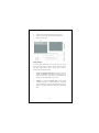
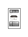
8 Ports Green Fast Ethernet PoE Metal Switch RFS-108P User Manual COPYRIGHT & TRADEMARKS Specifications are subject to change without notice. is a registered trademark of Rosewill Inc. Other brands and product names are trademarks or registered trademarks of their respective holders. No part of the specifications may be reproduced in any form or by any means or used to make any derivative such as translation, transformation, or adaptation without permission from Rosewill Inc. Copyright © 2010 Rosewill Inc. All rights reserved. http://www.rosewill.com FCC STATEMENT This equipment has been tested and found to comply with the limits for a Class A digital device, pursuant to part 15 of the FCC Rules. These limits are designed to provide reasonable protection against harmful interference in a residential installation. This equipment generates, uses and can radiate radio frequency energy and, if not installed and used in accordance with the instructions, may cause harmful interference to radio communications. However, there is no guarantee that interference will not occur in a particular installation. If this equipment does cause harmful interference to radio or television reception, which can be determined by turning the equipment off and on, the user is encouraged to try to correct the interference by one or more of the following measures: Reorient or relocate the receiving antenna. Increase the separation between the equipment and receiver. Connect the equipment into an outlet on a circuit different from that to which the receiver is connected. Consult the dealer or an experienced radio/ TV technician for help. This device complies with part 15 of the FCC Rules. Operation is subject to the following two conditions: 1) This device may not cause harmful interference. 2) This device must accept any interference received, including interference that may cause undesired operation. Any changes or modifications not expressly approved by the party responsible for compliance could void the user’s authority to operate the equipment. NOTE: THE MANUFACTURER IS NOT RESPONSIBLE FOR ANY RADIO OR TV INTERFERENCE CAUSED BY UNAUTHORIZED MODIFICATIONS TO THIS EQUIPMENT. SUCH MODIFICATIONS COULD VOID THE USER’S AUTHORITY TO OPERATE THE EQUIPMENT. 2 CE Mark Warning This is a class A product. In a domestic environment, this product may cause radio interference, in which case the user may be required to take adequate measures. Safety Warning Place connecting cables carefully so that no one will step on them or stumble over them. Always disconnect all cables from this device before servicing or disassembling. Use ONLY an appropriate power adaptor or cord for your device. Connect the power adaptor or cord to the right supply voltage (for example, 110V AC in North America or 230V AC in Europe). Do not allow anything to rest on the power adaptor or cord and do not place the product where anyone can walk on the power adaptor or cord. Do not use the device if the power adaptor or cord is damaged as it might cause electrocution. If the power adaptor or cord is damaged, remove it from the power outlet. Do not attempt to repair the power adaptor or cord. Contact your local vendor to order a new one. Do not use the device outside, and make sure all the connections are indoors. Do not obstruct the device ventilation slots, as insufficient airflow may harm your device. Do not use this product near water, eg, in wet basement, or near a swimming pool. Do not expose your device to dampness, dust or corrosive liquids. Do not install, use, or service this device during a thunderstorm. There is a remote risk of electric shock from lightning. Connect ONLY suitable accessories to the device. Do not open the device or unit. Opening or removing covers can expose you to dangerous high voltage points or other risks. ONLY qualified service personnel should service or disassemble this device. Please contact your vendor for further information. Make sure to connect the cables to the correct ports. If you wall mount your device, make sure that no electrical lines, gas or water pipes will be damaged. Your product is marked with this symbol, which is known as the WEEE mark. WEEE stands for Waste Electronics and Electrical Equipment. It means that used electrical and electronic products should not be mixed with general waste. Used electrical and electronic equipment should be treated separately. 3 Package Contents The following contents should be found in your package: One RFS-108P Switch One power cord This User Guide Racket-mount brackets Wall-mount kit Note: Make sure that the package contains the above items. If any of the listed items are damaged or missing, please contact with your distributor. Introduction The device is a powerful, high-performance Fast Ethernet Switch, with all 8 ports capable of 10 or 100Mbps auto-negotiation operation (NWay), which means this switch could automatically negotiate with the connected partners on the network speed and duplex mode. It is ideal for micro-segmenting large networks into smaller, connected subnets for improved performance, enabling the bandwidth demanding multimedia and imaging applications. Moreover, the 10/100Mbps auto-sensing ability provides an easy way to migrate 10Mbps to 100Mbps network with no pain. This switch supports PoE, which supplies power for connected devices via CAT 5 and above twisted cables. By integrating the data transmitting cable and power cord, it eliminates the effort constructing your network. You could easily connect a Wireless AP or a VoIP phone to this switch without looking outlets for them. Over current protection and circuit shorting protection are also supported to ensure the safety. The switch is plug-n-play without any software to configure and also fully compliant with all kinds of network protocols. Moreover, the rich diagnostic LEDs on the front-panel provide the operating status of individual port and whole system. Key Features Compliant with IEEE802.3az Energy Efficient Ethernet which allows individual ports to enter a low power idle based on data flow usage. 4 IEEE 802.3af Power over Ethernet (PoE) Standard Compliant: - Up to 15.4 watts maximum per Port (Port 1~4); - Supports PoE Over Current Protection; - Supports PoE Circuit Shorting Protection - Supports PoE Powered Device(PD) classification identify allows to detect power range Complies with 10BASE-T specifications of the IEEE802.3 standard Complies with 100BASE-TX specifications of the IEEE802.3u standard Push on/off button to enable/disable IEEE802.3az Compliant with IEEE 802.3af PoE standard (DTE power via MDI) Provides 4 PoE ports with classification identify Supports 15.4W maximum per PoE port Supports over current protection and circuit shorting protection 8 * RJ-45 ports for 100BASE-TX and 10BASE-T connectivity Supports NWay protocol for speed (10/100Mbps) and duplex mode (Half/Full) auto-detection Supports MDI/MDI-X auto crossover Wire-speed packet filtering and forwarding rate Store-and-forward architecture filters fragment & CRC error packets Supports 1K MAC entries 768K Bits buffer memory Supports extensive LED indicators for network diagnostics Internal universal switching power supply EMC: CE, FCC Class A Safety: LVD Front Panel The front panel consists of LED indicators and the ports. 5 LEDs Definition The switch contain 1x Power LED for the device, 1x 10/100M LED for each port and 1x PoE LED for port 1 ~ port 4. LED Power Link/ ACT Status Operation Steady Green Off 10M: Green 100M: Amber Blinking 10M: Green 100M: Amber Off The switch is powered on The switch is powered off Green PoE Off The port is connected Data transmitting /receiving. No valid link on this port One PoE compliant device is connecting with this port. There is no PoE compliant device connecting with this port. RJ-45 Ports All the RJ-45 ports in the device are auto-negotiating and auto-crossover. An auto-negotiating port can detect and adjust to the optimum Ethernet speed (10/100 Mbps) and duplex mode (full duplex or half duplex) of the connected device. An auto-crossover (auto-MDI/MDI-X) port automatically works with a straight-through or crossover Ethernet cable. 802.3az ON/OFF button Press in the 802.3az ON/OFF button on the device to turn on the EEE (Energy efficient Ethernet) feature. Disable it if the remote side doesn’t support EEE or you don’t want the network performance to be impacted due to the latency from the additional time required for the sleep and wake transition. Rear Panel The rear panel consists of one power receptacle and a push button to turn on and off. 6 Power Receptacle To be compatible with the electric service standards around the world, the switch is designed to afford the power supply in the range from 100 ~ 240VAC, 50/60Hz. Please make sure that your outlet standard to be within this range. To power on the switch, plug the female end of the power cord firmly into the receptacle of the switch and the other end into an electric service outlet. After the power cord installation, please check if the power LED is illuminated for a normal power status. Installation This switch can be placed on your desktop directly, or mounted in a rack, or mount on wall. The installation is a snap. Users can use all the features of the switch with simply attaching the cables and turning the power on. Before installing the switch, we strongly recommend: 1. The switch is placed with appropriate ventilation environment. a minimum 25mm space around the unit is recommended. 2. The switch and the relevant components are away from sources of electrical noise such as radios, transmitters and broadband amplifiers 3. The switch is away from environments beyond recommend moisture Desktop Installation 1. Install the switch on a level surface that can support the weight of the unit and the relevant components. 2. Plug the switch with the female end of the provided power cord and plug the male end to the power outlet. Wall mount Installation 1. Screw the two provided screws into the wall 150 mm apart 7 horizontally. Leave a small gap between the head of the screw and the wall. The gap should be big enough for the screw heads to slide into the screw slots and the connection cables to run down the back of the switch. 2. Align the holes on the back of the switch with the screws on the wall. Hang the switch on the screws. Warning! Do not wall mount the product vertically or it will be dangerous. Please attach the product on the wall horizontally! See the image below for reference: Rack-mount Installation The switch can be mounted on an EIA standard size, 19-inch rack or in a wiring closet with other equipment. Follow the steps below to mount your switch on a standard EIA rack using a rack-mounting kit. Rack-mounted installation requirements 1. Two mounting brackets 2. Eight M3 flat head screws and #2 philips screwdriver. 3. Four M5 flat head screws and #2 philips screwdriver. Procedures to Rack-Mounting the Switch in the rack: 1. Disconnect all the cables from the switch before continuing. 2. Place the unit the right way up on a hard, flat surface with the front facing you. 3. Locate a mounting bracket over the mounting holes on one side of the unit. 4. Insert the screws and fully tighten with a suitable screwdriver. 8 5. Repeat the two previous steps for the other side of the unit. 6. Insert the unit into the rack and secure with suitable screws. 7. Reconnect all the cables. Network Cables In making a switch interconnection, you could use any port to connect another switch with straight or crossover cable. As all the ports support auto MDI / MDI-X function, using a straight cable to make a switch-to-switch connection is allowed. 1. Crossover or straight-through cable: All the ports on the switch support Auto-MDI/MDI-X functionality. Both straight-through or crossover cables can be used to connect the switch with PCs as well as other devices like switches, hubs or router. 2. Category 3, 4, 5, 5e or 6 UTP/STP cable: To make a valid connection and obtain the optimal performance, appropriate cables corresponding to different transmitting/receiving speed is required. To choose a suitable cable, please refer to the following table. 9 Media 10/100 Mbps ports Ports that support PoE (Port 1~Port4) Speed Wiring 10 Mbps Category3,4,5 UTP/STP or above. 100 Mbps Category 5 UTP/STP or above. 10/100 Mbps Category5,5e UTP/STP or above. Network Application The following picture is an application sample of network topology for your reference: Product Specifications Standard Interface Network Data Rate Transmission Mode IEEE802.3 10BASE-T IEEE802.3u 100BASE-TX IEEE802.3az Energy Efficient Ethernet IEEE802.3af Power over Ethernet IEEE802.3x flow control 8 * 10/100 Mbps auto MDI/MDI-X RJ-45 ports (Port1~4 support PoE power feeding) 1* IEEE802.3az on/off button 10/100 Mbps Auto-negotiation 10/100Mbps Full/ Half duplex System: Power LED indications Ports: Link/ACT, PoE 10 Memory Emission Safety Power Consumption Operating Temperature Operating Humidity Power Supply Appendix A: 1. 1K MAC entries 768K Bits buffer Memory CE, FCC Class A LVD 75W Max. 00 ~ 400C (320 ~ 1040F) 10% - 90%(non-condensing) Input :100-240V, 50/60MHz, 1.5A Max Output:48VDC/1.56A Troubleshooting The Power LED is not lit Make sure the AC power cord connected the Switch with power source properly. 2. Make sure the power source is ON. The Link/Act LED is not lit when a device is connected to the corresponding port Make sure that the cable connectors are firmly plugged into the Switch and the device. Make sure the connected device is turned on and working well. The cable must be less than 100 meters long (328 feet). Thank you for purchasing a quality Rosewill Product. Please register your product at: www.rosewill.com for complete warranty information and future support for your product. Rosewill Customer Service Hotline: 1-800-575-9885 Rosewill Customer Service Support: [email protected] 11