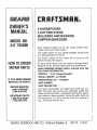
1
[
UAL
EL °
247.795890
®
Caution:
ReadandFollow
AllSafetyRules
andInstructions
BeforeOperating
ThisEquipment
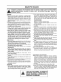
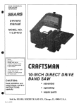
9 HORSEPOWER
3 CUTTING STAGE
MULCHING AND BAGGING
CHIPPER=SHREDDER
Assembly
Operation
CustomerResponsibilities
Serviceand Adjustment
RepairParts
I
SEARS,R0EBucK ANDCO.,HoffmanEstates,iL 60179U.S.A.
= = =,,H,HIH=
Printed in U.S,A.
'H
::::::::::::::::::::::
770-8902K
1t95
...................................................................
i
i ....
i i, ,,, i, i,,i
SAFETY RULES
SAFETY
INSTRUCTIONS.
WARNING:
REDUCE
PERSONAL TO
INJURY.
FAILURE
TO COMPLY
WITH "THE INSTRUCTIONS
MAY RESULT
tN
THE POTENTIAL
FOR ANY tNJURY_ COMPLY
WITH THE FOLLOWING
TRAINING
® Read this owner's manual carefully in its entirety before
attempting to assembte or operate this machine Be completely familiar with the controls and the proper use of this
machine before operating it., Keep this manual in a safe
place for future and regular reference and for ordering
replacement parts,
® Children must never be atlowed to operate this equipment
o No one should operate this unit while intoxicated or while
taking medication that impairs the senses or reactions
® This equipment should never be operated in the vicinity
of children, pets or other persons.
® Never run your machine in an enclosed area as the
exhaust from the engine contains carbon monoxide, which
is an odorless, tasteless and deadly poisonous gas
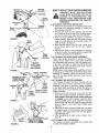
o Never place your hands or any part of your body or clothing inside the feeding chamber, discharge chute, or near
any moving part while the machine or eng+ne is running.
o If it is necessary for any reason to inspect or repair the
feeding chamber or any part of the machine where a mov+
ing part can come in contact with your body or clothing,
stop the machine, aIlow it to coo!, disconnect the spark
plug wire from the spark plug and move it away from the
spark plug before attempting such inspection or repair+
PREPARATION
e Wear safety glasses provided with your unit while operating the chipper-shredder to prevent injury from any material which may be ejected out of the openings,
o Wear proper apparel. Avoid wearing loose fitting clothing.,
Wear gloves when handling material
G,HANDLE GASOLINE WITH CARE as it is an extremely
flammable fuel
o Check the fuel before starting the engine Do net fill the
fuel tank indoors, while the engine is running, or while the
engine is still hot Turn the unit off and let the engine cool
before refueling,
e Fuel your chipper-shredder
in a clean area, Do not
smoke while refueling,,
o Fuel tank cap must be secure at all times except during
refueling.
o Avoid spilling gasoline or oil, Wipe the unit clean of any
spilled fuel or oil,,
• Stere fuel and oil in approved containers, away from heat
or open flame, and out of reach of children
• This machine should be operated only upon a level surface
® Assure that all screws, nuts and bolts and other fasteners
are properly secured.
OPERATION
• When feeding shreddable material into this equipment,
be extremely careful that pieces of metal, rocks, bottles,
cans or other foreign objects are not included Personal
injury or damage to the machine could result_
If the cutting mechanism strikes any foreign object or if
your machine should start making an unusual noise or
vibration, immediately stop the engine, disconnect the
spark plug wire from the spark plug and move it away
from the spark plug Allow the machine to stop and take
the following steps:
Inspect for damage
Replace or repair any damaged parts,
Check for any loose parts and tighten to assure continued safe operation,
o The engine must be kept clean of debris and other accumulations.
e Do not allow an accumulation of processed material to
build up in the discharge area as this will prevent proper
discharge and can result in kick-back from feed opening
e Never place your hands or any other part of your body or
clothing inside the feeding chamber, discharge chute or
near any moving part while the engine is running
o Keep all guards and deflectors in place and in good working condition to assure continued safe operation
o Always stand clear of the discharge area when operating
this machine,
a Keep your face and body back from the feed opening to
avoid accidental bounce back of any material,,
o Do not over+reach., Keep proper balance and footing at all
times
e The engine governor settings on your machine must not
be altered, changed, or tampered with The governor
controls the maximum safe operating speeds and protects the engine and all moving parts from damage
caused by overspeed,
_,
Do net transport machine while engine is running
e Do not operate engine if air cleaner or cover directly over
carburetor air intake is removed, except for adjustment,,
Removal of such parts could create a fire hazard
MAINTENANCE AND STORAGE
G, When this equipment is stopped for servicing, inspection,
storage or to change an accessory, make sure the spark
plug wire is disconnected from the spark plug and moved
away from the spark plug. The machine should be
allowed to coo! down before making such inspection,
adjustments, service, etc, Maintain your machine with
care and keep it clean for the best and continued safe
operation
Do not use flammable solutions to clean the air fitter.
When not in use, your machine should be stored out of
the reach of children+ Keep where gasoline fumes will not
reach an open flame or spark For long periods of storage, refer to the "Storage" section of this manual.
t
LOOK FOR THIS SYMBOL TO POINT OUTI
IMPORTANT SAFETY PRECAUTIONS. ITI
MEANS--ATTENTION!!! BECOiViEALERT!!!
YOUR SAFETY IS INVOLVED,
CONGRATULATIONS
on your purchase of a Sears
Craftsman Chipper-Shredder
It has been designed, engineered and manufactured
to give you the best possible
dependability and performance
Should you experience
any problem you cannot easily
remedy, please contact your nearest Sears Service Center/
Department in the United States, We have competent, welltrained technicians and the proper tools to service or repair
this unit.
Please read and retain this manual The instructions will
enable you to assemble and maintain your chipper-shredder
properly Always observe the "SAFETY RULES"
PRODUCT SPECIFICATIONS
Horsepower:
9..0
Engine Oil:
API Classification
SAE 30
(26 ounces)
SG or SH
Fuel Capacity:
Spark
1 Gallon
(Unleaded)
Plug (Gap
,,030 in.):
Champion
(or Equivalent)
MO6EL
NUMBER
J19LM
247,795890
Tire Pressure:
35-40 p.si,
SERIAL
NUMBER
MAINTENANCE
DATE OF
PURCHASE
THE MODEL AND SERIAL NUMBERS WILL BE FOUND
ON A LABEL ATTACHED
TO THE FRAME OF THE
CHIPPER-SHREDDER
YOU SHOULD RECORD BOTH SERIAL NUMBER AND
DATE OF PURCHASE AND KEEP IN A SAFE PLACE
FOR FUTURE REFERENCE
CUSTOMER
RESPONSIBILITIES
o Read and observe the safety rules
• Follow a regular schedule in maintaining,
caring for
and using your chipper-shredder
• Follow the instructions
under "Customer
Responsibilities"
and "Storage"
sections
of this Owner's
Manual,
AGREEMENT
A Sears Maintenance
Agreement
is available
on this
product. Contact your nearest Sears store for details.
WARNING: This unit is equipped with an internal combustion engine and should not be used on or near any unimproved forest-covered, brush-covered or grass-covered land
unless the engine's exhaust system is equipped with a
spark arrester meeting applicable local or state laws (if any)
If a spark arrester is used, it should be maintained in effective working order by the operator.
In the State of California the above is required by law
(Section 4442 of the California Public Resources Cede).
Other states may have similar laws Federal laws apply on
federal lands A spark arrester for the muffler is available
through your nearest Sears Authorized Service Center (See
the REPAIR PARTS section of this manual)
FULL ONEYEAR WARRANTYON CRAFTSMANGAS CHIPPER-SHREDDER
For one year from the date of purchase, when this Craftsman
chipper-shredder
is maintained,
lubricated,
and
tuned up according
to the operating and maintenance
instructions
in the operator's
manual, Sears will repair,
free of charge, any defect in material or workmanship.
This warranty
excludes
the blades, chipper blades, flails, air cleaners,
which are expendable
parts and become worn during normal use.
If this chipper-shredder
the date of purchase
is used for commercial
WARRANTY
SERVICE IS AVAILABLE
UNITED STATES. THIS WARRANTY
STATES
This warranty
gives
you specific
SEARS
this warranty
plugs,
catcher
applies
bags
and tires,
for only 30 days from
BY CONTACTING
THE NEAREST SEARS SERVICE CENTER IN THE
APPLIES
ONLY WHILE THIS PRODUCT
tS IN USE 1N THE UNITED
legal rights,
ROEBUCK
or rental purposes,
spark
and you may also have other rights which vary from state to state,
AND CO,, DEPT. 817WA,
HOFFMAN
ESTATES,
iL 60179
TABLE OF CONTENTS
RULES
..............................................................
2
CUSTOMER RESPONSIBILITIES ................................
11, 12
STO RAG E .................................................................
13
PRODUCT SPECIFICATIONS ...........................................
3
SERVICE AND ADJUSTMENT .....................................
13-I5
WARRANTY ..........................................................................
3
TROUBLE SHOOTING .............................................. I6
INDEX ................................................................................................
4
ACCESSORIES ............................................................................
4
REPAIR PARTS--CHIPPER-SHREDDER
........ 17, 18
REPAIR PARTS--ENGINE .....................................19-23
ASSEMBLY ...........................................................................
5-7
PARTS ORDERING/SERVICE .................
BACK COVER
OPERATION ....................................................................
7-10
SAFETY
INDEX
A
Accessories ...........................................................................
4
M
Maintenance:
Agreement .............................................................
3
Adjustments:
Carburetor ..............................................................................
15
Schedule ...............................................................................
I1
Engine ............................................................... 1!, 12
Engine Speed ...............................................................
15
Throttle .................................................................................
15
Chipper-Shredder ............................................................
11
O
Assembly Instruction's:
Oil ..................................................................................................
9
Catcher Bag .....................................................................................
6
Chute Deflector .............................................................6
Operating Tips ....................................................................8
R
Hopper Assembly .............................................................................
6
Catcher Bag ......................................................... 6, 7
Repair/Replacement Parts .............................................
17-23
C
Responsibilities, Customer .................................3, 11-13
S
Catcher Bag .............................................................................
6, 7
Controls ........................................................................................
7
Safety Rules ..................................................................... 2
Customer Responsibilities ..........................................
3, 11,12
Sharpening ....................................................................
14, I5
Service Recommendations .............................................
1t
E
Spark Plug .................................................................................
12
Engine:
Maintenance ...................................................... l t, 12
Specifications .....................................................................3
Starting .....................................................................................
10
Storage ......................................................................... 13
T
Stopping .............................................................................
8
Table of Contents ..............................................................4
Storage .............................................................................
13
F
Trouble Shooting .......................................................................
16
Fuel ........................................................................................
9
U
L
Unclogging ............................................................................
13, 14
Lubrication ...............................................................
11
Unpacking ......................................................................................
5
W
Warranty ..................................................................................................
3
i ,
i i
ii
i uu,uul,,,ulllllUllllll,l,uul,l,,i
iii
ii,
i,
ii1,1,
i
lu,,,ll
i
i
ul,
i ,u ulllu,u
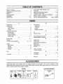
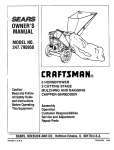
ACCESSORIES
These accessories were available when the chipper-shredder was purchased. They are also available at most
Sears retail outlets, catatog and service centers_ Most Sears stores can order repair parts for you, when you provide the model number of your chipper-shredder.
ENGINE
i 5park
i }'s|Lla
m
i
Air
Filter
Muffler
Engine i
Oil
CHIPPER-SHREDDER
Gas Can
Stabilizer
Tow Hitch
Kit
ASSEMBLY iNSTRUCTIONS
ii
i
i ,11 iiii ,11,1,1i i1,11,11,111111
.......................................... N,IIIIII,II,II
i
i
IMPORTANT: This unit is shipped WITHOUT GASOLINE or OIL in the engine. After assembly, see operation section of this manual for proper fuet and engine
oil recommendations
Flat ---__
Washer | (
) |
Nut 5/16-18
'_"- Hex Lock
Thread
NOTE: To determine right and left hand sides of your
chipper-shredder, stand behind and face the hopper
(engine is at the front of the unit).
Your chipper-shredder has been completely assembted at the factory, except for the hopper assembly
(hopper hood and upper leaf ramp section have been
sub-assembled), upper guide assembly, chute deflector and the catcher bag. The hardware pack safety
glasses and a bottle of oil are also included in the
carton..
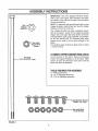
The hardware pack contains the parts shown in figure
1 (shown full size)_
TOREMOVE
CHIPPER-SHREDDER
FROMCARTON
Hex Bolt
5/16-18 x 8-3/8" Long
Cut the corners of the carton. Remove all packing
inserts. Roll chipper-shredder out of the carton. Make
certain atl parts and literature have been removed
before the carton is discarded.
TOOLS REQUIRED FORASSEMBLY
(1) Phillips Screwdriver
(2) 1/2" or Adjustable Wrenches
(2) 7/16" or Adjustable Wrenches
Machine Screws
1/4-20 x 1/2" Long
Hex Lock Nuts
1/4-20 Thread
FIGURE 1.
Housing
Assembly
Spacers
HOWTOSET-UPYOURCHIPPER-SHREDDER
WARNING:
Bolt
_
Chute
Deflector
Hex
Nut
Hand
Knob
\
/
/
/
FIGURE 2.
Stop
Washer
Release
Bar
Upper
Guide
Assembly
Bolt
8-3/8" Long
Flat Washer
Hex Lock Nut
FIGURE 3.
Hopper Pivot
Door
Hopper Assembly
TRUSS SCREW
AND NUT FIRST
Bar
Guide
Assembly
pper
Leaf
Ramp
Section
Remove Truss
Screw and Nut
FIGURE 4.
-Plunger
FIGURE 5.
MAKE
CERTAIN
SPARK
ENGINE)
DISCONNECTED
PLUG WIREIS (LOCATED
ON TOPAND
OF
MOVED AWAY FROM SPARK PLUG
BEFORE ASSEMBLING
THE CHIPPERSHREDDER°
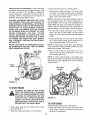
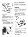
+.<-ATTACHING THE CHUTE DEFLECTOR
e Remove the hand knobs and cupped washers from
each side of the discharge opening on the left side
of the chipper-shredder+
o Remove hex lock nut, two spacers and hex bolt
from inside the hinge on top of the housing assembly+ Do not remove one spacer from the hex bolt.
• Place the chute deflector in position on the discharge opening° Insert hex bolt and spacer through
hinge on chute deflector and housing (spacer fits
inside of hinge).. See figure 2.
e Place second spacer over hex bolt, inside other
part of hinge+ Secure with hex lock nut+ Tighten
securely
o Secure both sides of chute deflector to housing
using hand knobs and cupped washers (cupped side
of washers go against chute deflector).
_+--ATTACHING THE UPPER GUIDE ASSEMBLY
Place upper guide assembly in position on frame,
making certain edges of the upper guide assembty
are underneath stop washers, and the release bar is
in the slots_ See figure 3 Insert hex bolt 8-3/8" tong
through upper guide assembly and frame. Secure
with flat washer and hex lock nut.
NOTE: Make certain upper guide assembly can pivot
by pulling up on release bar and lowering upper guide
assembly_ If necessary, loosen hex lock nut a turn or
two+ Put the upper guide assembly back into the
raised position..
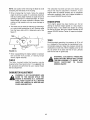
<_-ATTACHING THE HOPPER ASSEMBLY
Your chipper-shredder
has been shipped with the
upper leaf ramp section attached to the hopper
assembly. See figure 4+ Attach the hopper assembly
to the upper guide assembly as follows+. Be certain to
place heads of all truss machine screws inside of
hopper assembly+.
o Remove one truss machine screw and nut from
each side of hopper assembly as shown in figure 4+
Push hopper pivot door down inside lower part
of hopper as you place hopper assembly (both
pieces) inside upper guide assembly. Replace
truss screws and nuts just removed, using the hole
shown in figure 4, one on each side+ Tighten finger
tight only.
o Place the six truss machine screws and nuts found
in hardware pack in the remaining holes of hopper
assembly, alternating sides of the unit and tightening finger tight only+
o After assembling all eight screws, tighten them
securely.
-<-A'I-I'ACHING THE CATCHER BAG
Your chipper_shredder is equipped with a catcher bag
to catch the shredded material.
• To attachthe bag,placethe openingof the bag
overthechutedeflectorsoit completely
coversthe
chuteopening,Depressthe plungeron the draw-
string,andpull on the drawstringuntilthe bagis
tightaroundthechuteopeningReleaseplungerto
lockit intopositionSeefigure5.
=
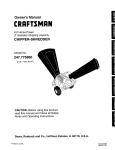
OPERATION
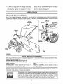
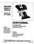
KNOWYOUR CHIPPER-SHREDDER
READ THIS OWNER'S MANUAL AND SAFETY RULES BEFORE OPERATING YOUR CHIPPER-SHREDDER,
Compare the illustrations with your chipper-shredder to familiarize yourself with the location of various controls
and adjustments. Save this manual for future reference..
Oil Fill
Hopper
Assembly
Muffler Dipstick
Spark Plug
and
Boot
Chipper
Chute
Chute
Deflector
Start_
Handle
cher
Bag
FIGURE 6.
= =
, ,
,
=
HH=
= 'H" 'H''"IH"H'.mH".'H'I=r..'I'IIr",'='V=_"
I',=.=
MEETSANSISAFETYSTANDARDS
Sears chipper-shredders
conform to the safety standard B71 6-1982 of the American National Standards Institute,
OPERATING
CONTROLS(See
RELEASE BAR--Used
raising or lowering
CHOKE LEVER--Used
figure 6)
to release the hopper when
to enrich the fuel mixture in
the carburetor when starting a cold engine.
STARTER
engine
THROTTLE
HANDLE--Used
CONTROL--Permits
to manually
start the
selection of fast or
slow engine speed.
BEFORE USING YOUR CHIPPER-SHREDDER,
AGAIN REFER TO THE "SAFETY RULES" AS SHOWN ON
PAGE 2 OF THIS MANUAL. ALWAYS BE CAREFUL..
The operation of any chipper-shredder can result in foreign objects being thrown into
the eyes, which can result in severe eye damage Always wear the safety glasses provided with the chipper-shredder or eye shields before chipping or shredding, or while
performing any adjustments or repairs, We recommend Wide Vision Safety Mask for
over spectacles or standard glasses available at Sears Retail or Catalog Stores
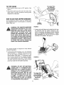
TO STOP ENGINE
* Move throttle
figure 6+
control lever to OFF position.
No Larger Than
1/2" Diameter
(Recommended)
Or 1" Diameter
(Maximum)
See
o Disconnect spark plug wire and move away from
spark plug to prevent accidental starting while
equipment is unattended,
HOW TO USE YOUR CHIPPER-SHREDDER
Do not attempt to shred or chip any material other
than vegetation found in a normal yard (i .e, branches,
leaves, twigs, etc+)+
WARNING: THE CHIPPER-SHREDDER
DISCHARGES
MATERIALS WITH CONSIDERABLE
VELOCITY.
KEEP AWAY
FROM THE AREA AROUND THE CHUTE
DEFLECTOR.
ALWAYS
STOP THE
ENGINE AND DISCONNECT THE SPARK
PLUG WIRE WHEN REMOVING
OR
ATTACHING THE BAG WHEN CHANGING
CONTAINERS OR WHEN REMOVING THE
SHREDDED MATERIAL+. WEAR SAFETY
GLASSES AND GLOVES WHENEVER
USING YOUR CHIPPER-SHREDDER.
The chipper-shredder
methods of operation.
is designed
DO NOT
Hopper
Assembly
FIGURE 7,
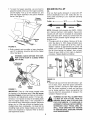
e Leaves and small twigs can be raked into the hopper assembly when the hopper assembly is lowered to the ground. See figure 8+ Small branches
up to 1/2" diameter (recommended)
or 1" diameter (maximum) can also be fed into the hopper
assembly in this position. See figure 9
for three different
e Leaves and small branches up to 1/2" diameter
(recommended) or 1" diameter (maximum) can be
fed into the hopper assembly when it is in the
raised position,. See figure 7+ If it becomes necessary to push material into the chipper-shredder,
use a small diameter stick--NOT YOUR HANDS,
The stick should be small enough that it will be
ground up if gets into the impeller assembly.
WARNING:
\
FIGURE 8.
PUT MATERIAL
LARGER THAN 1/2" IN DIAMETER (RECOMMENDED)
or 1" DIAMETER (MAXIMUM) INTO THE HOPPER ASSEMBLY.
MATERIAL UP TO A MAXIMUM OF 3" IN
DIAMETER
MATERIAL
MAY BE FED
INTO THE CHIPPER CHUTE. DO NOT
ATTEMPT
TO SHRED OR CHIP ANY
MATERIAL LARGER THAN 3" IN DIAMETER, PERSONAL INJURY OR DAMAGE
TO THE MACHINE COULD RESULT_
No Larger Than
1/2" Diameter
(]
Or 1" Diameter
(Maximum)
FIGURE 9.
To lower the hopper assembly, use one hand to
grasp the handle at the top of the hopper assembly
and lift slightly. Pull up on the release bar, and
lower the hopper assembly to the ground.. Release
the bar.. See figure I0
Hopper
Assembly
Bar
FIGURE 10.
o Bulky material, such as stalks or heavy branches,
up to 3" in diameter, should be fed into the chipper
chute. See figure 11..
WARNING:
MAKE CERTAIN
GASAND OIL FILL-UP
OIL
Only use high quality detergent oil rated with API
service classification SG or SH Select the oil's viscosity grade according
temperature.
Colder
-._
to your expected
32°F--'--_
operating
Warmer
NOTE: Although multi-viscosity oils (5W30, 10W30,
etc ) improve starting in cold weather, these multF
viscosity oils wil! result in increased oil consumption
when used above 32°F Check your oil level more frequently to avoid possible engine damage from running low on oil,
o Fill engine with oil as follows Remove oil fill dipstick, See figure 12, With chipper-shredder
level,
use a funnel to fill engine with oil to FULL mark on
dipstick, Capacity is approximately 26 ounces, Be
carefub not to overfill. Tilt chipper-shredder toward
the left [from behind the hopper), then re-level,,
Check oil level, Refill to FULL mark on dipstick if
necessary,, Replace dipstick and tighten_
THE CHIP-
PER tN
NOT
CHUTE
USE_ DOOR IS CLOSED
WHEN
3" Maximum
Diameter
Oil
Fill
Dipstick
Drain
FIGURE 12,
Oil
Drain
FIGURE 11.
IMPORTANT:
Chipper
Chute
There is a flail screen located inside
the housing in the discharge area. if the flail screen
becomes clogged, remove and clean as instructed in
the Service and Adjustments section. For best performance, it is important to keep the shredding blade
and the chipper blades sharp, If the composition of
the material being discharged changes (becomes
stringy, etc.) or if the rate at which the material is discharged slows down considerably, it is likely that the
shredding blade and/or chipper blades are dull and
need to be sharpened or replaced. Refer to Service
and Adjustments section.
GAS
® Remove fuel cap and fill fuel tank with about 1 gallon of clean, fresh, lead-free grade automotive
gasoline. DO NOT use Ethyl or high octane gasoline. Be certain container is clean and free from
rust or foreign particles. Never use gasoline that
may be stale from long periods of storage in the
container.. Replace fuel cap.
WARNING: DO NOT FILL CLOSER THAN
1/2 INCH OF TOP OF FUEL TANK TO
PREVENT SPILLS AND TO ALLOW FOR
FUEL EXPANSION.
IF GASOLINE
IS
ACCIDENTLY SPILLED, MOVE CHIPPERSHREDDER
AWAY FROM AREA OF
SPILL. AVOID CREATING ANY SOURCE
OF IGNITION UNTIL GASOLINE VAPORS
HAVE DISAPPEARED.
Check the fuel level periodically to avoid running out
of gasoline while operating the chipper-shredder If the
unit runs out of gas as it is shredding or chipping, it
may be necessary to unclog the unit before it can be
restarted
Refer to "Removing the Flail Screen" in
SERVICE AND ADJUSTMENT section
o Move choke lever down to CHOKE position.
Grasp starter handle (see figure 13) end pull rope
out slowly until engine reaches start of compres_
sion cycle (rope will pull slightly harder at this
point) Let the rope rewind slowly
NOTE: A noise will be heard when finding the start of
the compression cycle This noise is caused by the
flails and fingers which are part of the shredding mechanism falling into place, and should be expected. In
addition, the flails and fingers will be noisy after the
engine is started, until the impeller reaches full speed.
WARNING: EXPERIENCE INDICATES THAT ALCOHOL BLENDED FUELS (CALLED GASOHOL OR
USING ETHANOL OR METHANOL) CAN ATTRACT
MOISTURE WHICH LEADS TO SEPARATION AND
FORMATION
OF ACIDS DURING
STORAGE.
ACIDIC GAS CAN DAMAGE THE FUEL SYSTEM
OF AN ENGINE WHILE IN STORAGE. TO AVOID
ENGINE
PROBLEMS,
THE FUEL
SYSTEM
SHOULD BE EMPTIED OR TREATED WITH FUEL
STABILIZER
BEFORE STORAGE FOR 30 DAYS
OR LONGER. USE FRESH FUEL NEXT SEASON.
SEE "STORAGE"
SECTION FOR ADDITIONAL
INFORMATION.
o Pull rope with a rapid, continuous, full arm stroke.
Keep a firm grip on start handle.. Let rope rewind
slowly. Do not let starter handle snap back against
starter.
e Repeat preceding two instructions
until engine
fires_ When engine starts, move choke lever on
engine halfway between CHOKE and OFF
NEVER USE ENGINE OR CARBURETOR CLEANER PRODUCTS IN THE FUEL TANK OR PERMANENT DAMAGE MAY OCCUR.
NOTE: If engine does not fire after three attempts,
move choke lever halfway between CHOKE and OFF
position and try again. See figure 14o
e Move throttle controt to IDLE position for a few
minutes warm-up. Move choke lever to OFF position as engine warms up
Spark Plug,
Boot
NOTE: In order to idle smoothly, a new engine may
require 3 to 5 minutes running above slow idle speed.
Idle speed has been adjusted to be correct after this
break-in period..
Throttle
Control
Full Choke
Position
Off
Position
Handle
FIGURE 13.
Lever
TO STARTENGINE
WARNING:
BE SURE NO ONE OTHER
THAN THE OPERATOR
tS STANDING
NEAR THE CHIPPER-SHREDDER
WHILE
STARTING
OR OPERATING,
DO NOT
OPERATE THIS CHIPPER-SHREDDER
UNLESS THE CHUTE DEFLECTOR HAS
BEEN PROPERLY INSTALLED
AND tS
SECURED WITH THE HAND KNOBS.
FIGURE 14.
TO STOP ENGINE
o Move throttle control lever to OFF position.
o Disconnect spark plug wire and move away from
spark plug to prevent accidental starting while
equipment is unattended.
o Attach spark plug wire and rubber boot to spark
plug. See figure 13
o Place the throttle control lever in FAST position.
10
...........................
=,,,=
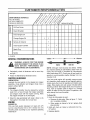
CUSTOMER
MAINTENANCE SCHEDULE
FILL IN DATES
AS YOU COMPLETE
REGULAR SERVICE
!
=H='H=I,"
"=
I
....
="
RESPONSIBIMTBES
/
o2" sERvicE
OATES
|
'-'
Oil Pivot Points
0
cc
Clean Shredder
4
,/
Check Engine Oil
",J
Change Engine Oil
LU
z
w
4
_/
4
Service Air Cleaner
4
Clean Engine Cylinder
,/
Spark Plug
Muffler
_/ CHECK
Colder
GENERALRECOMMENDATIONS
WARNING: ALWAYS STOP THE ENGINE
AND DISCONNECT
THE SPARK PLUG
WIRE
BEFORE
PERFORMING
ANY
MAINTENANCE OR ADJUSTMENTS.
o Periodically
are tight.,
32°F
_
Warmer
NOTE: Although multi-viscosity oils (SE30, 10W30,
etc.) improve starting in cold weather, these multi- viscosity oils will result in increased oil consumption
when used above 32°F Check your oil level more frequently to avoid possible engine damage from running low on oil
check all fasteners and be sure they
o Follow the Maintenance Schedule above
CHIPPER-SHREDDER
Your four-cycle engine will normally consume some
oil--therefore, check engine oil level regularly approximately every five hours of operation and before each
usage.. Stop engine and wait several minutes before
checking oil level. With engine level, the oil must be to
FULL mark on dipstick (refer to figure 12). Change
engine oil after the first five hours of operation, and
every twenty-five hours thereafter..
LUBRICATION
Lubricate the pivot points on the release bar, hopper
assembly, chute deflector and chipper chute once a
season using a light oil
CLEANING
o The chipper-shredder may be cleaned by running
water from a hose through the hopper assembly
and chipper chute with the engine running° Allow
the chipper-shredder to dry thoroughly.
To Drain Oil:
e Drain oil while engine is warm.
e Wash the bag periodically with water Allow to dry
thoroughly in the shade. Do not use heat.
a. Remove oil drain plug. Refer to figure 11. Catch
oil in a suitable container.
ENGINE
ENGINE OIL
Only use high quality
service classification
-.,_,_--_
b. When engine is drained of all oil, replace drain
plug securely.
o Refill with fresh oil. Refer to GAS AND OIL FELLUP section..
detergent oil rated with API
SG or SH. Select the oil's
viscosity grade according to your expected operating
temperature.
o Replace dipstick.
11
AIRCLEANER
The air cleanerpreventsdamagingdirt, dust,etc,
fromenteringthe carburetorandbeingforcedintothe
engine and is important to engine life and performance
Never run your engine without
pletely assembled.
Yearly or every 25 hours, whichever occurs first,
remove the blower housing and clean the areas
shown in figure 16 to avoid overspeeding, overheating
and engine damage. Clean more often if necessary.
WARNING: PERIODICALLY CLEAN MUFFLER AREA TO REMOVE ALL GRASS,
DIRT AND COMBUSTIBLE DEBRIS.
air cleaner com-
To Service Air Cleaner:
Service pre-cleaner after every 25 hours of use, or at
least once a season.. Service filter every 100 hours of
use, or at least once a season.. Service pro-cleaner and
filter more often under dusty conditions.
e Remove wing nut and cover. See figure t5
e Slide pre-cleaner off filter_ Clean the inside of base
and cover thoroughly.
• Clean pre-cleaner as follows.
Wash in water and detergent solution, and squeeze
(do not twist) until all dirt is removed°
FIGURE 16.
Rinse thoroughly in clear water.
SPARK PLUG
The spark plug should be cleaned and the gap reset
to .030" at least once a season or every 50 hours of
operation° See figure 17. Spark plug replacement is
recommended at the start of each season.. Refer to
engine parts list for correct spark plug type_
Wrap in a clean cloth and squeeze (do not twist)
until completely dry, or allow to air dry.
® If necessary, replace filter (do not attempt to clean)..
e Install new filter on base.. Slide pre-cleaner
filter_
e Install cover
securely.
Base
and wing
Filter
nut° Tighten
Pre-Cleaner
over
wing
NOTE: Do not sandblast spark plug. Spark plug
should be cleaned by scraping or wire brushing and
washing with a commercial solvenL
nut
Wing
,030" Feeler Gauge
_rk Plug
FIGURE 17,
FIGURE 15.
MUFFLER
Do not operate the chipper-shredder without a muffler
or tamper with the exhaust system. Damaged mufflers
or spark arrestors could create a fire hazard. Inspect
periodically, and replace if necessary. If your engine
is equipped with a spark arrestar screen assembly,
remove every 50 hours for cleaning and inspection
Replace if damaged.
Cover
CLEAN ENGINE
Clean engine periodically
Remove dirt and debris
with a cloth or brush, Cleaning with a forceful spray of
water is not recommended as water could contaminate the fuel system.
12
STORAGE
Prepare your chipper-shredder for storage at the end
of the season or if the unit wilt not be used for 30 days
or more.
e Drain the fuel tank,
o Start the engine and let it run until the fuel lines and
carburetor are empty.
o Never use engine or carburetor cleaner products in
the fuel tank or permanent damage may occur
o Use fresh fuel next season,
WITH FUEL IN THE FUEL TANK INSIDE
WARNING;
NEVER
STORE
MACHINE
OF BL.IILDING
WHERE
FUMES
MAY
REACH AN OPEN FLAME OR SPARK, OR
WHERE
IGNITION
SOURCES
ARE
PRESENT SUCH AS HOT WATER AND
SPACE HEATERS, FURNACES, CLOTHES
DRYERS, STOVES, ELECTRIC MOTORS,
ETC.
NOTE: Fuel stabilizer is an acceptable alternative in
minimizing the formation of fuel gum deposits during
storage. Add stabilizer to gasoline in fuel tank or storage container Always follow the mix ratio found on
stabilizer container. Run engine at least 10 minutes
after adding stabilizer to allow the stabilizer to reach
the carburetor. Do not drain the gas tank and carburetor if using fuel stabilizer.
NOTE: A yearly check-up by your local Sears Service
Center is a good way to make certain your chippershredder will provide maximum performance for the
next seasonr
o Drain atl the oil from the crankcase (this should be
done after the engine has been operated and is still
warm) and refill the crankcase with fresh oil.
CHIPPER-SHREDDER
e Clean the chipper-shredder
o If you have drained the fuel tank, protect the inside
of the engine as foNows, Remove spark plug, pour
approximately t/2 ounce (approximately one tablespoon) of engine oil into cylinder and crank slowly
to distribute oil Replace spark plug.
thoroughly.
o Wipe unit with an oiled rag to prevent rust (use a
light oil or silicone)
ENGINE
IMPORTANT:
iT tS IMPORTANT
TO PREVENT
GUM DEPOSITS FROM FORMING IN ESSENTIAL
FUEL SYSTEM PARTS SUCH AS CARBURETOR,
FUEL FILTER, FUEL HOSE, OR TANK DURING
STORAGE.. ALSO, EXPERIENCE INDICATES THAT
ALCOHOL BLENDED FUELS (CALLED GASOHOL
OR USING ETHANOL
OR METHANOL)
CAN
ATTRACT MOISTURE WHICH LEADS TO SEPARATION AND FORMATION OF ACIDS DURING STOR m
AGE. ACIDIC GAS CAN DAMAGE THE FUEL SYSTEM OF AN ENGINE WHILE IN STORAGE.
OTHER
o Do not store gasoline from one season to another.
o Replace your gasoline can if your can starts to rust.
Rust and/or dirt in your gasoline will cause problems
• Store unit in a clean, dry area., Do not store next to
corrosive materials, such as fertilizer.
NOTE: If storing in an unventilated or metal storage
shed, be certain to rustproof the equipment by coating
with a light oil or silicone°
SERVICE & ADJUSTMENT
WARNING: ALWAYS STOP ENGINE AND
DISCONNECT SPARK PLUG WIRE AND
MOVE IT AWAY FROM SPARK PLUG
BEFORE PERFORMING
ANY ADJUSTMENTS OR REPAIRS.
e Loosen the two hand knobs on each side of the
chute deflector. Lift the chute deflector up, and tie it
out of the way.
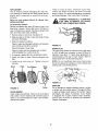
REMOVINGTHEFLAILSCREEN
e Remove two hairpin clips from the clevis pins which
extend through the housing.. Remove the clevis
pins. Lift the flail screen from inside the housing.
See figure t8.
tf the discharge area becomes clogged, remove the
flail screen and clean area as follows.
o Clean the screen by scraping
water_ Reinstall the screen.
o Stop the engine, make certain the chipper-shredder
has come to a complete stop and disconnect spark
plug wire from the spark plug before unclogging the
chute
NOTE: Be certain to reassemble the flail screen with
the curved side down as shown in figure 18.
13
or washing
with
Replace or sharpen blades. If sharpening, make certain to remove an equal amount from each blade
Reassemble in reverse order.
Make certain blades are reassembled with the sharp
edge facing the direction shown in figure 18 (sharp
edge is assembled toward the slotted opening in the
impeller assembly).r
SHREDDING BLADE
The shredding blade may be removed for sharpening
or replacement as follows.
o Disconnect spark plug wire and move it away from
spark plug.
o Lower the hopper assembly. Block up the housing
See figure 2Q
FIGURE18,
o Remove the six hex lock nuts and lock washers
HandKnobs
from the housing weld bolts using a 1/2" wrench..
Separate the chipper-shredder into two halves
SHARPENING
ORREPLACING
THEBLADES
o Remove the back-up plate.
CHIPPER BLADES
NOTE: When reassembling, make certain the opening on the back-up piate is toward the bottom of the
uniL The back-up plate may be reversed to provide a
new cutting edge,
= Disconnect spark plug wire and move it away from
spark plug.
• Remove the flail screen as instructed in previous
section.,
o Remove the chipper chute by removing three hex
nuts and washers.. A 1/2" wrench is required. See
Allen
Screws
figure 18..
NOTE: When reassembling, the cupped washer goes
on the bottom of the chipper chute with the cupped
side against the chute..
e Rotate the impeller assembly by hand until you
locate one of the chipper biades in the chipper
chute opening Remove the blade, using a 3/16"
allen wrench on the outside of the blade and 1/2"
wrench on the impeller assembly (inside the housing), See figure 19
Pipe
Sharp
e Remove the other blade in the same manner
FIGURE 20.
Torque
Wrench
o Loosen the two hand knobs and cupped washers
which secure the chute deflector, and raise the
chute deflector
a Insert a !/2" or 3/4" diameter pipe through the ftaii
screen into the impeller to keep it from turning, or
remove the flail screen and insert a piece of wood
(2 x 4) into the chute opening,
e Remove the two outside screws on the biade,
using a 3/16" allen wrench and a 1/2" wrench.,
e Remove the blade by removing the center bolt, lock
washer and flat washer
FIGURE 19.
14
NOTE:Usecautionwhenremovingthebladetoavoid
contacting
theweldboltsonthehousing,
o Whensharpeningthe blade, fotlowthe original
angleofgrindas a guide,it is extremely
important
thateachcuttingedge receives an equal amount of
The carburetor has been pre-set at the factory and
should not require adjustment
However, if your
engine does not operate properly due to suspected
carburetor problems, take your chipper-shredder
to
your nearest SEARS Service Center.
grinding to prevent an unbalanced b}ade An unbaF
anced blade will cause excessive vibration when
ENGINESPEED
rotating at high speeds and may cause damage to
the unit,
Your engine speed has been factory set, Do not
attempt to increase engine speed or it may result in
personal injury. If you believe the engine is running
too fast or too slow, take your chipper-shredder to the
nearest SEARS Service Center for repair and adjustmenL
o The blade can be tested for balance by balancing it
on a round shaft screwdriver or nail. Remove metal
from the heavy side until it is balanced evenly_ See
figure 21
TIRES
\
Recommended
operating tire pressure is 35 to 40
posoio(sidewall of tire may give tire manufacturer's recommended pressure), Equal tire pressure should be
maintained on both tires, When installing a tire to the
rim, be certain rim is clean and free of rust, Lubricate
both the tire and rim generously.
FIGURE 21.
o When reassembling the blade, tighten to between
550 and 650 inch pounds, or lacking torque
wrench, tighten securely,
WHEN SEATING BEADS MAY CAUSE
WARNING:
EXCESSIVE
PRESSURE
TIRE/RIM ASSEMBLY
TO BURST
WITH
FORCE
SUFFICIENT
TO
CAUSE
SERIOUS INJURY.
FLAILS
The flails, located inside the housing,
may be
reversed when they become dull, It is suggested that
this procedure be performed by your nearest Sears
Service Department
CARBURETORADJUSTMENT
WARNING: tF ANY ADJUSTMENTS ARE
MADE TO THE ENGINE WHILE THE
ENGINE IS RUNNING (EoG. CARBtJRETOR), KEEP CLEAR OF ALL MOVING
PARTS. BE CAREFUL OF HEATED SURFACES AND MUFFLER.
15
.................
_m
Jill
TROUBLE
i,,u,,nl,
SHOOTING
,
in,
n
:::::::::::::::::::::::::
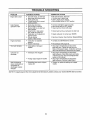
PROBLEM
POSSIBLE CAUSE(S)
CORRECTIVE ACTION
Engine fails to start
=
o
o
e
•
=
=
•
Loss of power;
operation erratic
= Spark plug wire loose.
= Unit running on CHOKE,
= Blocked fuel lineor stale fuel,
fresh gasoline,
o Water or dirt in fuel system
tank, Refill with fresh fuel
e Carburetor out of adjustment
Service Center.
• Dirty air cleaner
section of this manual.
o Connect and tighten spark plug wire..
• Move choke lever to OFF position.
• Clean fuel line; filf tank with clean
Engine overheats
Q Carburetor not adjusted
properly.
• Engine oil level low,
• Contact your SEARS Service Center,.
Too much vibration
o Loose parts or damaged
impeller,
= Stop engine immediately and disconnect
spark plug wire. Tighten all bolts and nuts.
Make alt necessary repairs If vibration continues,
have unit serviced by a SEARS Service Center.
Unit does not
discharge
o Discharge chute clogged
• Stop engine immediately and disconnect
spark plug wire. CIean flail screen and inside
of blower housing. See Service!Adjustments
section of this manual
= Stop engine immediately and disconnect
spark plug wire. Remove lodged object.
Fuel tank empty, or stale fuel.
Spark plug wire disconnected
Faulty spark plug
Throttle control not in correct
starting position.
• Shredding blade and/or chipper
blades dull.
Disconnect fuel line at carburetor to drain fuel
• Adjust carburetor or contact your SEARS
• Service air cleaner
•
o Foreign object lodged in impeller.
Rate of discharge
slows considerably or
composition of
discharged material
changes
•
Fill tank with clean, fresh fuel.
Connect wire to spark p_ug
Clean, adjust gap or replace.
Move throttle control to FAST position
See Customer Responsibilities
Fill crankcase with proper oil.
• Sharpen or replace shredding and chipper
blades..
NOTE: For repairs beyond the minor adjustments listed above, please contact your nearest SEARS Service Center.
16
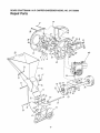
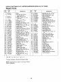
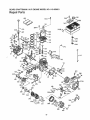
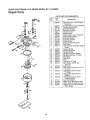
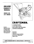
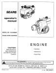
SEARS
CRAFTSMAN
9 H.P. CHIPPER-SHREDDER
MODEL
NO, 247.795890
Repair Parts
22
I!
56
l
47
I
57
so/
51
64
45
52
17
63
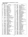
SEARS
CRAFTSMAN
9 H.P. CHIPPER-SHREDDER
MODEL NO. 247.795890
Repair Parts
KEYI
NO,, i
PART
NO,
KEY
NO.
DESCRIPTION
I
I
PART
NOo
DESCRIPTION
._i-i+
2
742-0571
710-1254
5
736-0217
736-0247
6
7
8
9
10
11
12
13
14
15
!6
17
t8
19
2O
22
23
24
25
26
27
28
29
30
31
32
33
34
35
36
37
38
39
11459B
711-0564
711-0833A
7'11-0834
715-0249
736-0192
681-0030
781-0490
710-1054
712-0411
736-0!19
710-0825
736-0142
750-0793
711-0835
7t2-0291
7t4-3010
781-0457
714-0149B
781-0480
712-3010
736-0242
720-0170
747-0744A
732-O542
781-0489
781-0475
736-0170
712-3010
781-0510A
710-0157
736-0119
710-3008
Blade
Hex Patch Bolt 3/8-24 x
2.25" Lg. (Gr. 8)
L-Wash, 3/8" I.D, H.D
Ft-Wash. 406" I,Do x 1,25"
O.D Hdn.
Flail _
9 _("_._._-,,,-,Flail Spacer
.
Clevis Pin ,496 Di&
Flail Spacer w/160" Dia. Hole
Spring Roll Pin 1.t2" Lg,
FI-Washo .531" I.D. x .94" OD.
Impeller Ass'yo Comp.l"
Chipper Blade
Flat Hd_ Scr. 5/16_24 x .75" Lg.
Hex Top L-Nut 5116-24 (Gr. 5)
L-Wash, 5116" LD_*
Hex Bolt 1/4-20 x &75" Lg.*
FI-Wash, ,281" I.rD. X .50" O.D,
Chute Hinge Spacer 1,66" Lg.
Clevis Pin 5" Dia. x 4.62" Lg.
Hex Ctr. L-Nut t/4-20 Thd
Cotter Pin
Shredder Screen
Internal Cotter Pin 3/8" Dia,
Chute Deflector Ass'y.
Hex Nut 5/16-18 Thd (Gr. 5)
Bell-Wash 345" I.D. x .88"
Hand Knob
Chipper Door Rod
Torsion Spring 1.14" Lgo
Chipper Door
Chipper Chute Ass'y.
Spec L-Wash, 5/16" !. D.
Hex Nut 5/I6-18 Th& (Gr. 5)
Shredder Frame
Hex Bolt 5/16-24 x °75" Lg,
L-Wash. 5/16" I,D,*
Hex Bolt 5/16-18 x ,75" Lg
(Gr. 5)
4O I 710-0442
41 I 681-0004
42 I 781-0474A
43 I 735-0639
44 t 143.959001
45 t 747-0531A
461 742-0546
47 I 712-0429
48 I 710-0601
49 I 11480
50 ] 736-0264
710-0542
52 i 781-0487B
53 ] t6522B
54 I 781-0494
55 i 16524B
56 i 710-0286
57
58
59
61
62
63
! 712-0107
1 11461B
I 726-0214
i 750-0786
I 738-0813
I 734-1597
734-1598
64 I 734-1455
65 I 741-0487
66 I 734-0255
67 I 737-0280
75 I 732-0629
76 I 747-0747
781-0492
78 I 781_0493
79! 726_0106
764-0199A
723-0400
770-8902K
ttncl. Ref 1, 6, 7, 8, 9, 10, 1t, 12, 13, 14
*Common Hardware--May
NOTE: Specifications
notice or obligation.
Be Purchased Locally.
subject
to change
without
18
Hex Bolt 5/16-18 x 15" Lg.*
Flail Housing Ass'y.--L H.
Flail Housing Ass'y.--RoH.
Spark Plug Boot
Engine--143959001
Release Bar
Torsion Spring 1.06" Lg.
Elastic Lock Nut 5/16-18 Thd,
Hex Wash, Hd. Self-Tap Scr,
5/16-18 x 25" Lg.
Stop Washer ,,
Fl-Wash. 5/16 1.D.
Hex Bolt 5/16-18 x 8.38" Lg.
Back-Up Plate
Inlet Guide Ass'y
Pivot Hopper Hood
Upper
Guide Scr.
Ass'y114-20 x 5"
Truss Mach,
Lg.
Hex L-Nut 1/4-20 Thd,
Upper Leaf Ramp Section
Push Cap 5/8" Dia. Rod
Spacer .64" I D x ,38" Lg,
Shredder Axle
Wheel Ass'y., Comp.
Tire Only
Rim Only
Flange Bearing ,,632" i.D.
Air Valve
Grease Fitting
Torsion Spring
Hopper Door Rod
Hopper--Pivot Door
Hopper Lockout Brkt,
Cap Speed Nut 1/4" Rod
Bag (Not Shown)
Safety Glasses (Not Shown)
Owner's Manual
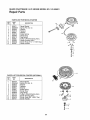
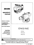
SEARS
CRAFTSMAN
9 H.P. ENGINE
MODEL NO. 143.95900'!
Repair Parts
400
370B,,
305
119
757'
,308
87
70
t-J
/110
/
69
10t
IO0
i
I
4
/
I
I
_173
25
.P
182
184
261
:;03
I
282
26
\
275
2O0
\
186
\
260
209
339
286
251
327
390
287
19
SEARS
CRAFTSMAN
9 H.P. ENGINE
MODEL
NO. 143.959001
Repair Parts
PART
NO.
35385
27852
34171
30969
30699C
30700
650494
33454
29916
650548
34663
35319
36460
650561
30322
36283
29826
29918
29216
29642
34552
34553
34554
34329A
34330A
3433tA
34332
34333
34334
27888
35373A
650908
650882
34034
35374
35375
33273A
650128
35262A
35376
35377
27642
35319
31845
30590A
35378
30588A
29193
650833
650832
32589
611090
650880
650881
35135
610118
KE
DESCRIPTION
Cylinder (lncl 2 & 20)
Dowet Pin
Oit Drain Extension
Extension Cap
Governor Rod
(Incl. 15A & 15B)
Governor Yoke
Screw, 6-40 x 5/16"
Governor Lever
Governor Lever Clamp
Screw, 8-32 x 5/16"
Speed Control Spring
Oil Seal
Blower Housing Baffle
Screw, 1/4-20 x 5/8"
Lock Nut, 8-32
Crankshaft
Screw, 10-32 x 3/4"
Lock Washer
Lock Nut, 10-32
Retaining Ring
Piston, Pin & Ring Set (Std_)
Piston, Pin & Ring Set
(.010" OS)
Piston, Pin & Ring Set (.020" OS)
Piston & Pin Ass y. (Std.) (IncL 43)
Piston & Pin Ass'y. (.010" OS)
(Incl. 43)
Piston & Pin Ass'y (.020" OS)
(IncL 43)
Ring Set (Std.!,
Ring Set (.010 OS)
Ring Set (.020" OS)
Piston Pin Retaining Ring
Connecting Rod Ass'y. IncL 46,
47 & 49)
Connecting Rod Bolt
Connecting Rod Bolt
Valve Lifter
Oil Dipper
Camshaft (MCR)
Blower Housing Extension
Screw, 10-24 x 1/2"
Cylinder Cover Gasket
Cylinder Cover (IncL 71, 75 & 80)
Crankshaft Bushing
Oil Drain Plug
Oil Seal
Governor Shaft
Washer
Governer Gear Ass'y. (incl. 8I)
Governer Spool
Retaining Ring
Screw, 1/4-20 x 1-3/16"
Screw, !/4-20 x 1-1 I/16"
Flywheel Key
qywheel
.ock Washer
Flywheel Nut
Solid State Ignition
Spark Plug Cover
2O
PART
NOo
12C
12_
125
650872
650814
35187
36448
36449
27878A
27880A
126
126
127
128
t29
130
131
135
139
140
149
149
150
15l
169
170
171
172
173
174
178
182
t84
185
186
200
203
204
206
207
209
215
223
224
238
239
240
242
245
245/
250
251
260
261
262
34035
34036
650691
650690
650727
650694A
650273
33636
33369
650836
27882
35862
27881
32581
27896A
28423
28424
28425
35350
650128
29752
30088A
33263
34707
34667
34677
31342
650549
610973
33878
650821
35882
650378
27915A
28820
27272A
33266
33267
33268
35881
33269A
650513
36250
650788
29747B
264_
265
275
276
277
285
286
650802
33272B
34!85B
31588
650729
35985B
35446
f
1 11_
DESCRIPTION
Solid State Mounting Stud
Screw, Torx %15, 10-24 x 1"
Ground Wire
Cylinder Head Gasket
Cylinder Head
Exhaust Valve (Std.) (lnct. 151)
Exhaust Valve (tt32" OS)
(Incl. t51)
Intake Valve (Std.) (lncL 151)
Intake Valve (1/32" OS) (]nck 15l
Washer
Belleville Washer
Screw, 5/16-18 x 1-3/4"
Screw, 5/16-18 x 2"
Screw, 5/16q8 x 5!8"
Resistor Spark Plug (RJ17LM)
Governor Gear Bracket
Screw, I0-24 x 1/2
Valve Spring Cap
Valve Spring Cap
Valve Spring
Valve Spring Keeper
Valve Cover Gasket
Breather Body
Breather Element
Valve Cover
Breather Tube
Screw, 10-24 x 112"
Nut & Lock Washer, 1/4-28
Screw, 1/4-28 x 1"
Carburetor To Intake Pipe Gasket
Intake Pipe
Governor Link
Control Bracket (Incl 203 & 204)
Compression Spring
Screw, 5-40 x 7/16
Terminal
Throttle Link
Screw, 10-32 x 1/2"
Oontrot Decal
Screw, Torx %30, 5/t6-18 x 1-118"
Intake Pipe Gasket
Screw, 10-32 x 1/2"
Air Cleaner Gasket
Air Cleaner Body
Air Cleaner Bracket
Air Cleaner Filter
Air Cleaner Filter
Air Cleaner Cover
Wing Nut, 1/4-20
Blower Housing
Screw, 5/16-18 x 3/4"
Screw, Torx T-40, 5/16-24 x
21/32"
Screw, 1/4-20 x 5/8"
Cylinder Head Cover
Muffler
Locking Plate
Screw, 5/16-18 x 3-3/16"
Starter Cup
Starter Screen
SEARS
CRAFTSMAN
9 H.P. ENGINE
MODEL NO. 143.959001
Repair Parts
KEY
NO.
KEY
PART
NO.
NO.
DESCRIPTION
29752
30962
26460
650665
34186A
35355
35554
35499
35540
36205
29443
35392
35880
34259
34258A
Nut & Lock Washer, I/4-28
Fuel Line
Fuel Line Clamp
Screw, 1/4-15 x 3/4"
Fuel Tank (IncL 292 & 301)
Fuel Cap
Oil Fill Tube
"O"-Ring
Fill Tube Clip
Dipstick
287
290
292
298
300
301
305
307
308
310
325
327
339
340
341
342
370
370A
370B
370C
38O
390
400
Spacer
Fuel Tank Bracket
Fuel Tank Bracket
PART
NOo
30063
Screw, Torx T-30, 1/4-20 x 1/2"
36261
Instruction Decal
35703
Throttle Decat
35532
Logo Decal
35274
Instruction Decal
632689
Carburetor (lnci. 184)
590671
Rewind Starter
Note: This engine could have been built
with 590704 starter, Refer to the design of the
air intake louvers for part identification.
Individual starter parts do not interchange
36454
Gasket Set (Incl. Part Nos.
27272A, 27896A, 27915A, 29673,
33263, 33629, 34698A, 35262 &
36448)
RPM Setting:
High Speed: 3450 to 3750
Low Speed: 1700
OPTIONAL SPARK ARRESTER
'
Part No. 34479A
21
DESCRIPTION
<____
SEARS
CRAFTSMAN
9 H.P. ENGINE
MODEL
NO. 143.95900'1
Repair Parts
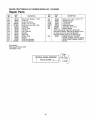
PARTS LIST FOR CARBURETOR
KEYI
NO. 1
PART
NO.
632689
I
I
22
1
2
4
5
6
7
10
11
12
13
14
15i
t61
17
632243
632244
631184
631183
632517
650506
632249
632043
631184
631183
632248
630735
632164
650417
18
20
2t
22
23
25
27
28
29
30
630766
632281
630766
630739
630740
631867
631024
632019
63'1028
631021
31
40
631022
632239
41
63O740
42
630739
43
630738
44
47
48
60
27110
630748
631027
632347
DESCRIPTION
Carburetor (Incl. 184 of Engine
Parts List)
Throttle Shaft & Lever Assembly
Throttle Return Spring
Dust Seal Washer
Dust Seal (Throttle)
Throttle Shutter
Shutter Screw
Choke Shaft & Lever Assembly
Choke Return Spring
Dust Seal Washer
Dust Seal (Choke)
Choke Shutter
Choke Positioning Spring
Fuel Fitting
Throttle Crack Screw/Idle Speed
Screw
Tension Spring
Idle Mixture Screw
Tension Spring
Idle Mixture Screw Washer
Idle Mixture Screw "O"-Ring
Float Bowl
Float Shaft
Float
Float Bowl "O"-Ring
Inlet Needle, Seat & Clip
(lncL 31 )
Spring Clip
Main Adj. Screw Ass'y,, (tncL 41
thru 44)
High Speed Mixture Screw
"O"-Ring
High Speed Mixture Screw
Washer
High Speed Mixture Screw
Tension Spring
Bowl Nut Washer
Welch Plug, Idle Mixture Well
Welch Plug, Atmospheric Vent
Repair Kit* (Incl, Items Marked
PK in Notes)
SEARS
CRAFTSMAN
9 H.P. ENGINE
MODEL
NO. 143.959001
Repair Parts
PARTS LIST FOR RECOIL STARTER
KEY
NO.
1
2
3
4
5
6
7
8
11
12
13
PART
NO,
590671
590599A
590600
590679
590601
590678
590680
590412
590681
590683
590456
590387
13
_
__1
DESCRIPTION
Recoil Starter
Spring Pin (Incl_ 4)
Washer
Retainer
Washer
Brake Spring
Starter Dog
Dog Spring
Pulley & Rewind Spring Ass'y,
Starter Housing Ass'y.,
Starter Rope (114"x tl/64" Di&)
Starter Handle
7"g
g"7
@"4
O3
@'2
PARTS LIST FOR RECOIL STARTER (OPTIONAL)
KEY
PART
NO,
NOn
-1
2
3
4
5
6
7
8
11
12
13
590704
590599A
590600
590696
590601
590697
590698
590699
590700
590705
590535
590701
DESCRIPTION
/
13
Recoil Starter
Spring Pin (lncl, 4)
Washer
Retainer
Washer
Brake Spring
Starter Dog
Dog Spring
Pulley & Rewind Spring Ass'yo
Starter Housing Ass'y_
Starter Rope (98" x 9/64" Di&)
Starter Handle
.-.-8
_--5
0--2
23
]
®
9 HORSEPOWER
3 CUTTING STAGE
MULCHING AND BAGGING
CHIPPER-SHREDDER
Each chipper-shredder
has its own model
engine has its own model number°
number_
The model number for your chipper-shredder
on a label attached to the frame.
The model number for the engine
blower housing of the engine.
H0WTOORDER
REPAIRPARTS
REPAIR SERVICE
1-800-4-REPAIR
(1-800-473-7247)
ORDERING PARTS
1-800-FON-PART
(1-800-366-7278)
will be found
be found
on the
All parts listed herein
may be ordered
through
Sears,
Roebuck and Co. Service Centers and most Retail Stores.
WHEN ORDERING
REPAIR
FOLLOWING
INFORMATION:
*PRODUCT
IF YOU NEED REPAIR
SERVICE OR PARTS:
will
Each
PARTS,
ALWAYS
GIVE
THE
- "9 H.P. Chipper-Shredder"
*MODEL
NUMBER
- 247.795890
*ENGINE
MODEL NO. - 143.95900'1
*PART NUMBER
*PART DESCRIPTION
Your Sears merchandise
has added value when you consider that Sears has service units nationwide
staffed with
Sears trained technicians_oprofessional
technicians
specifically trained on Sears products, having the parts, tools and
the equipment
to insure that we meet our pledge
to
you__"we service what we sello"
SEARS, ROEBUCK AND CO., Hoffman Estates, IL
60179
U.S.A.