1
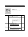
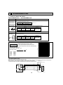
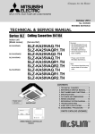
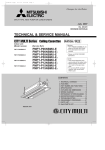
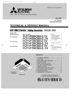
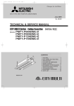
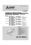
SPLIT-TYPE, HEAT PUMP AIR CONDITIONERS
May 2009
No. OCH462
TECHNICAL & SERVICE MANUAL
R410A R22
Indoor unit
[Model names]
[Service Ref.]
PKFY-P24NKMU-E
PKFY-P30NKMU-E
PKFY-P24NKMU-E.TH
PKFY-P30NKMU-E.TH
Note:
• This manual describes
only service data of the
indoor units.
• RoHS compliant products
have <G> mark on the
spec name plate.
CONTENTS
INDOOR UNIT
1. PART NAMES AND FUNCTIONS .......... 2
2. SPECIFICATION ..................................... 4
3. OUTLINES AND DIMENSIONS .............. 6
4. WIRING DIAGRAM ................................. 7
5. REFRIGERANT SYSTEM DIAGRAM.......... 8
6. MICROPROCESSOR CONTROL ........... 9
7. TROUBLESHOOTING .......................... 14
8. DISASSEMBLY PROCEDURE ............. 21
PARTS CATALOG (OCB462)
1
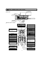
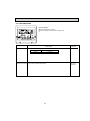
PART NAMES AND FUNCTIONS
Front grille
Indoor unit
Filter
Air inlet
Emergency operation
switch
Air outlet
Vane
Louver
Wireless remote controller
CHECK TEST RUN display
CHECK and TEST RUN display indicate that
the unit is being checked or test-run.
MODEL SELECT display
display
Lights up while the signal is transmitted to
the indoor unit when the button is pressed.
display
Blinks when model is selected.
SET TEMP. display indicates the set desired
temperature.
CLOCK display
display
Displays the current time.
OPERATION MODE display
Operation mode display indicates which
operation mode is in effect.
TIMER display
CHECK TEST RUN
MODEL SELECT
°F
°C
AMPM
Displays when in timer operation or when
setting timer.
“
AMPM
NOT AVAILABLE
display
The vertical direction of air flow is indicated.
ON/OFF
“
TEMP
”“
” display
Displays the order of timer operation.
”“
” display
Displays whether timer is on or off.
display
button
FAN SPEED display indicates which fan
speed has been selected.
FAN
AUTO STOP
VANE
AUTO START
SET TEMPERATURE button sets any desired
room temperature.
ON/OFF button
The unit is turned ON and OFF alternately
each time the button is pressed.
MODE
TIMER CONTROL buttons
CHECK LOUVER
h
FAN SPEED SELECT button
Used to change the fan speed.
MODE SELECT button
TEST RUN
SET
min
RESET
AUTO STOP (OFF timer): when this switch is
set, the air conditioner will be automatically
stopped at the preset time.
AUTO START (ON timer): when this switch is
set, the air conditioner will be automatically
started at the preset time.
CLOCK
Used to switch the operation mode between
cooling, drying, fan, heating and auto mode.
h and min buttons
Buttons used to set the “hour and minute” of
the current time and timer settings.
+ In case the outdoor unit is cool only type,
the heating and auto mode are not
available.
LOUVER button
Changes left/right airflow direction.
CHECK-TEST RUN button
(Not available for this model.)
Only press this button to perform an
inspection check or test operation.
Do not use it for normal operation.
CLOCK button
RESET button
VANE CONTROL button
SET button
Used to change the air flow
2
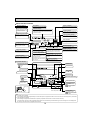
Wired remote controller
Display Section
For purposes of this explanation,
all parts of the display are shown
as lit. During actual operation, only
the relevant items will be lit.
Day-of-Week
“Sensor” indication
Shows the current day of the week.
Displayed when the remote controller
sensor is used.
Time/Timer Display
Shows the current time, unless the simple or Auto Off
timer is set.
If the simple or Auto Off timer is set, the time to be
switched off is shown.
“Locked” indicator
Indicates that remote controller buttons have been locked.
Identifies the current operation
“Clean The Filter” indicator
Shows the operating mode, etc.
*Multilanguage display is available.
To be displayed on when it is time to
clean the filter.
TIME SUN MON TUE WED THU FRI SAT
TIMER
Hr
ON
AFTER
Indicates that operation from the
remote controller has been prohibited by a master controller.
FUNCTION
FILTER
°F°C
°F°C
“Centrally Controlled” indicator
Timer indicators
AFTER OFF
ERROR CODE
The indicator comes on if the corresponding timer is set.
WEEKLY
SIMPLE
AUTO OFF
ONLY1Hr.
Fan Speed indicator
Shows the selected fan speed.
“Timer is Off” indicator
Indicates that the timer is off.
Up/Down Air Direction indicator
The indicator shows the direction of the outcoming airflow.
Room Temperature display
Shows the room temperature. The room
temperature display range is 46–102°F.
The display blinks if the temperature
is less than 46°F or 102°F or more.
Ventilation indicator
Appears when the unit is running in
Ventilation mode.
“One Hour Only” indicator
Temperature Setting
Shows the target temperature.
Displayed if the airflow is set to
Low or downward during COOL
or DRY mode. (Operation varies
according to model.)
The indicator goes off in one hour,
at which time the airflow direction
also changes.
Louver display
Indicates the action of the swing louver.
Does not appear if the louver is not
running.
(Power On indicator)
Indicates that the power is on.
Operation Section
ON/OFF button
Temperature setting buttons
Down
Fan Speed button
Up
Timer Menu button
(Monitor/Set button)
Filter
button
(<Enter> button)
Mode button (Return button)
TEMP.
ON/OFF
Set Time buttons
Check button (Clear button)
Back
Ahead
Timer On/Off button
(Set Day button)
Test Run button
MENU
BACK
PAR-21MAA
MONITOR/SET
ON/OFF
FILTER
DAY
CLOCK
CHECK TEST
OPERATION
Airflow Up/Down button
CLEAR
Louver button
(
Operation button)
To return operation
number
Opening the
lid
Built-in temperature sensor
Ventilation button
( Operation button)
To go to next operation
number
Note:
● “PLEASE WAIT” message
This message is displayed for approximately 3 minutes when power is supplied to the indoor unit or when the unit is recovering from a power failure.
● “NOT AVAILABLE” message
This message is displayed if an invalid button is pressed (to operate a function that the indoor unit does not have).
If a single remote controller is used to operate multiple indoor units simultaneously that are different types, this message will not be displayed as
far as any of the indoor units is equipped with the function.
3
2
SPECIFICATION
2-1. Specifications
PKFY-P30NKMU-E
PKFY-P24NKMU-E
Model
1-phase 208-230V 60Hz
Power source
Cooling capacity
(Nominal)
*1
*1
Power input
Current input
Heating capacity
(Nominal )
*2
*2
Power input
Current input
External finish
External dimension H × W × D
Net weight
Heat exchanger
Fan
kW
Btu/h
kW
A
kW
Btu/h
kW
A
7.0
24,000
0.04
0.29
7.9
27,000
0.04
0.29
8.8
30,000
0.06
0.43
10.0
34,000
0.06
0.43
Plastic, MUNSELL (1.0Y 9.2/0.2)
365 × 1170 × 295
14-3/8" × 46-1/16" × 11-5/8"
21 (46)
Cross fin (Aluminum fin and copper tube)
mm
in.
kg (lb)
Line flow fan × 1
0
0
DC motor
Type × Quantity
External
static press.
Pa
mmH2O
Motor type
Motor output
kW
0.056
Direct-drive
Driving mechanism
Airflow rate
(Low-High)
m3/min
L/s
cfm
dB <A>
Noise level (Low-High)
(measured in anechoic room)
Insulation material
Air filter
Protection device
Refrigerant control device
Connectable outdoor unit
Diameter of
(R410A) mm (in.)
Liquid
refrigerant pipe
(R22)
Gas
20 - 24
333 - 400
710 - 850
16 - 20
267 - 333
570 - 710
43 - 49
39 - 45
Polyethylene sheet
PP honeycomb
Fuse
LEV
R410A, R22 CITY MULTI
ø9.52 (ø3/8")
ø9.52 (ø3/8")
ø15.88 (ø5/8")
ø15.88 (ø5/8")
(R410A) mm (in.)
(R22)
mm (in.)
Flare
Flare
Flare
Flare
Field drain pipe size
Standard
Document
attachment
Accessory
Optional parts
External heater adapter
Remarks
Installation
Note :
Indoor :
Outdoor :
Pipe length :
Level difference :
*1 Nominal cooling conditions
ø9.52 (ø3/8")
ø9.52 (ø3/8")
ø15.88 (ø5/8")
ø15.88 (ø5/8")
Flare
Flare
Flare
Flare
I.D. 16mm (5/8")
Installation Manual, Instruction Book
PAC-YU25HT
Details on foundation work, insulation work, electrical wiring, power source switch, and other items shall be referred to
the Installation Manual.
Unit converter
*2 Nominal heating conditions
80°FDB/67°FWB (26.7°CDB/19.4°CWB)
95°FDB (35°CDB)
25 ft. (7.6 m)
0 ft (0 m)
70°FDB(21°CDB)
47°FDB/43°FWB (8.3°CDB/6.1°CWB)
25 ft. (7.6 m)
0 ft (0 m)
* Due to continuing improvement, above specification may be subject to change without notice.
4
kcal/h
Btu/h
cfm
lb
= kW × 860
= kW × 3,412
= m3/min × 35.31
= kg/0.4536
*Above specification data is
subject to rounding variation.
2-2. Electrical parts specifications
Service Ref.
PKFY-P24NKMU-E.TH
Symbol
PKFY-P30NKMU-E.TH
Parts name
Room temperature
thermistor
TH21
Resistance 30°F/15.8k, 50°F/9.6k, 70°F/6.0k, 80°F/4.8k, 90°F/3.9k, 100°F/3.2k
Liquid pipe thermistor
TH22
Resistance 30°F/15.8k, 50°F/9.6k, 70°F/6.0k, 80°F/4.8k, 90°F/3.9k, 100°F/3.2k
Gas pipe thermistor
TH23
TH24
Resistance 30°F/15.8k, 50°F/9.6k, 70°F/6.0k, 80°F/4.8k, 90°F/3.9k, 100°F/3.2k
Fuse
(Indoor controller board)
FUSE
250V 3.15A
Fan motor
MF
8-Pole Output 56W / RCOJ56-AC
Vane motor
(with limit switch)
MV
MSBPC20 DC12V
Linear expansion valve
LEV
Power supply terminal
block
TB2
(L1, L2, GR) 250V 20A
TB5
(M1, M2, S) 250V 20A
TB15
(1, 2) 250V 10A
Transmission terminal
block
MA remote controller
terminal block
EFM-40YGME
DC 12 V
EFM-80YGME
DC 12 V
2-3. Sound levels
Sound level at anechoic room : Low-High
Sound level dB (A)
Service Ref.
39 - 45
PKFY-P30NKMU-E.TH
43 - 49
3.3 ft.
(1m)
PKFY-P24NKMU-E.TH
3.3 ft.
(1m)
Measurement location
* Measured in anechoic room.
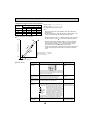
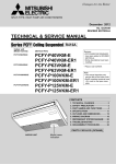
2-4. NC curves
PKFY-P30NKMU-E
External static pressure : 0Pa
Power source : 208,230V, 60Hz
70.0
High speed
Low speed
65.0
60.0
NC60
55.0
50.0
NC50
45.0
40.0
NC40
35.0
30.0
NC30
25.0
20.0
Approximate minimum
audible limit on
continuous noise
NC20
15.0
10.0
63
125
250
500
1k
2k
4k
OCTAVE BAND CENTER FREQUENCIES(Hz)
8k
OCTAVE BAND PRESSURE LEVEL (dB) 0dB = 20MPa
OCTAVE BAND PRESSURE LEVEL (dB) 0dB = 20MPa
PKFY-P24NKMU-E
External static pressure : 0Pa
Power source : 208,230V, 60Hz
70.0
High speed
Low speed
65.0
60.0
NC60
55.0
50.0
NC50
45.0
40.0
NC40
35.0
30.0
NC30
25.0
20.0
Approximate minimum
audible limit on
continuous noise
NC20
15.0
10.0
63
125
250
500
1k
2k
4k
OCTAVE BAND CENTER FREQUENCIES(Hz)
5
8k
OUTLINES AND DIMENSIONS
PKFY-P24NKMU-E.TH
PKFY-P30NKMU-E.TH
Unit : inch (mm)
5-17/132(140.3)
2-9/16(65.2)
Top side
17(431.7)
7/16(11)
16-11/16(423.7)
Left side
Right side
Front side
14-3/8(365)
Mount board
Knock out hole
for left piping
C
2-29/32(74)
9-1/2(241)
33-21/32(855)
46-1/16(1170)
A
3/16(5)
11-5/8(295)
Operation lamp
Front side(Grille open)
Knock out hole
for right piping
DEFROST/STAND BY lamp
Receiver
2-3/32(53)
1-1/4(32)
23/32(18)
Terminal block for power supply
Terminal block for transmission
Terminal block for
MA-remote controller
Emergency operation switch
(cooling/heating)
Filter hook
1-3/16(30)
1-3/8(35)
17-15/32(444)Gas pipe
2-19/32(66)
4-27/32(123)
18-31/32(482)Liquid pipe
23-1/32(585)Drain hose
6-1/16(154)
5-9/32(134)
Under side
Piping connection
Vane(auto)
Louver(manual)
B
Liquid pipe
B
Knock out hole
for lower piping
Sleeve
(purchased locally)
:2-15/16
(:75)
Through hole
Gas pipe
:2-15/16~:3-5/32
(:75~:80)
Drain hose
Refrigerant pipe: 3/8 O.D(:9.52)
Flared connection: 3/8F
Refrigerant pipe: 5/8 O.D(:15.88)
Flared connection: 5/8F
5/8(:16) O.D
Required space(Indoor unit)
2-9/16(65)
B
3-1/32(77)
3-7/16(87)
2-9/16(65)
13/32(10.7)
1/8(3)
2-1/8(54)
0
Center measurement hole
:3/32(:2.5)
5/8(15.5)
14-11/32(364)
15-1/8(384.5)
16-3/32(408.5)
17-9/32(439)
17-7/8(454)
18-5/16(465.5)
Mount board
12-3/8(314)
4-11/32(110)
2-3/8(60)
13/32(10)
0
13/32(10)
2-3/8(60)
4-11/32(110)
12-3/8(314)
17-7/8(454)
17-9/32(439)
16-3/32(408.5)
15-1/8(384)
14-11/32(364)
20-3/8(517.4)
4-:11/32(:9) Bolt hole
75-:3/16(:5.1)
Tapping
screw hole
Indoor unit outline
2-1/8(54)
1-1/4(32)
31/32(25)
1/2(12.5)
0
1/2(12.5)
1-15/32(37.5)
2-15/32(62.5)
3-7/16(87.5)
4-1/8(104.5)
5-3/32(129.5)
0
31/32(25)
1-31/32(50)
2-15/16(75)
3-15/16(100)
4-19/32(117)
4-29/32(125)
5-19/32(142)
7-9/16(192)
9-17/32(242)
6-9/16(167)
8-17/32(217)
9-1/32(229.5)
10-13/32(264)
11-1/2(292)
11(279.5)
11-1/2(292)
Wall hole for
right rear piping
6
23-1/32(585)
17-11/16(449.2)
13-11/32(339)
13-3/4(349.2)
15-1/8(384)
8-17/32(216.5)
0
15-1/8(384)
13-11/32(339)
7-7/16(189)
Knock out hole for
rear piping
2-15/16×18-29/32(75×480)
37.5)
/32(R
R1-15
16-15/16(430.5)
12-5/32(308.5)
12-1/4(311)
Wall hole for
left rear piping
A
5/16(7.8)
5/16(7.8)
2-5/8(67)
3-1/32(77)
Min.1-7/8(48)
C
Min.9-27/32(250)
Min.2(50.5)
Min.8-21/32(220)
Min.2-27/32(72.4)
23-1/32(585)
Min.9/32(7)
Air outlet
3-1/32(77)
2-5/8(67)
Knock out hole for piping
Air inlet
20-7/8(530.5)
3
2-9/16(65)
4
WIRING DIAGRAM
PKFY-P24NKMU-E.TH
SYMBOL
I.B
CN24
CN32
CN51
CN52
BZ
DSA
FUSE
LED1
LED2
SW2
SW3
SW4
SWE
X1
MOV 01,02
LEV
MF
MV
TB2
TB5
TB15
PKFY-P30NKMU-E.TH
SYMBOL
NAME
INDOOR CONTROLLER BOARD
CONNECTOR EXTERNAL HEATER
TH21
REMOTE SWITCH
TH22
CENTRALLY CONTROL
REMOTE INDICATION TH23
BUZZER
SURGE ABSORBER
FUSE (T3.15AL 250V)
POWER SUPPLY (I.B)
POWER SUPPLY (I.B)
SWITCH CAPACITY CODE
MODE SELECTION
MODE SELECTOR
DRAIN PUMP (TEST MODE)
AUX.RELAY DRAIN PUMP
VARISTOR
LINER EXPANSION VALVE
FAN MOTOR
VANE MOTOR
TERMINAL POWER SUPPLY
BLOCK
TRANSMISSION
MA-REMOTE CONTROLLER
TH24
A.B
SWA
SW1
SW11
SW12
SW14
S.B
SWE1
SWE2
W.B
LED1
LED2
RU
NAME
THERMISTOR ROOM TEMP. DETECTION
(32°F/15kΩ, 77°F/5.4kΩ)
PIPE TEMP. DETECTION/LIQUID
(32°F/15kΩ, 77°F/5.4kΩ)
PIPE TEMP. DETECTION/GAS1
(32°F/15kΩ, 77°F/5.4kΩ)
PIPE TEMP. DETECTION/GAS2
(32°F/15kΩ, 77°F/5.4kΩ)
ADDRESS BOARD
FAN SPEED SELECTOR
SWITCH
MODE SELECTION
ADDRESS SETTING 1s DIGIT
ADDRESS SETTING 10ths DIGIT
BRANCH No.
For the detail, refer to Fig. 1.
SWITCH BOARD
EMERGENCY OPERATION (HEAT)
EMERGENCY OPERATION (COOL)
PCB FOR WIRELESS REMOTE CONTROLLER
LED (OPERATION INDICATION: GREEN)
LED (OPERATION INDICATION: ORANGE)
RECEIVING UNIT
<Fig. 1>
See Fig. 1.
7
5
REFRIGERANT SYSTEM DIAGRAM
PKFY-P24NKMU-E.TH
PKFY-P30NKMU-E.TH
Gas pipe thermistor (1) TH23
Strainer (#50mesh)
Gas pipe
Gas pipe thermistor (2) TH24
Flare connection
Liquid pipe thermistor TH22
Heat exchanger
Liquid pipe
Linear expansion valve
Strainer1 (#50mesh)
Strainer2 (#100mesh)
Strainer (#100mesh)
Room temparature thermistor TH21
Unit : mm (inch)
Model
PKFY-P24NKMU-E
PKFY-P30NKMU-E
Gas pipe
:15.88 (5/8)
:15.88 (5/8)
Liquid pipe
:9.52 (3/8)
:9.52 (3/8)
Item
8
6
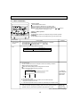
MICROPROCESSOR CONTROL
INDOOR UNIT CONTROL
6-1. COOL OPERATION
<How to operate>
Press POWER ON/OFF button.
Press the operation MODE button to display COOL.
Press the TEMP. button to set the desired temperature.
NOTE: The set temperature changes 2°F when the
or
pressed one time. Cooling 67 to 87°F
TIME SUN MON TUE WED THU FRI SAT
TIMER
Hr
ON
AFTER
AFTER OFF
ERROR CODE
FUNCTION
FILTER
ûFûC
ûFûC
WEEKLY
SIMPLE
AUTO OFF
ONLY1Hr.
TEMP.
MENU
BACK
PAR-21MAA
MONITOR/SET
ON/OFF
ON/OFF
FILTER
DAY
CLOCK
Control modes
1. Thermoregulating
function
button is
CHECK TEST
OPERATION
CLEAR
Control details
1-1. Thermoregulating function (Function to prevent restarting for 3 minutes)
• Room temperature
desired temperature + 2°F ···Thermo ON
• Room temperature
desired temperature ···Thermo OFF
Remarks
1-2. Anti-freezing control
Detected condition : When the liquid pipe temp. (TH22) is 32°F or less in 16
minutes from compressors start up, anti-freezing control
starts and the thermo OFF.
Released condition : The timer which prevents reactivating is set for 3 minutes,
and anti-freezing control is cancelled when any one of the
following conditions is satisfied.
Liquid pipe temp. (TH22) turns 50°F or above.
The condition of the thermo OFF has become complete
by thermoregulating, etc.
The operation modes became mode other than COOL.
The operation stopped.
3. Vane
(up/down vane change)
By the remote controller setting (switch of 2 speeds)
Type
Fan speed notch
2 speeds
[Low], [High]
(1) Initial setting: Start at COOL mode and horizontal vane.
(2) Vane position:
Horizontal →Downward A →Downward B →Downward C→Downward D→Swing→Auto
→
2. Fan
(3) Restriction of the downward vane setting
When setting the downward vane A, B, C or D in [Low] of the fan speed notch,
the vane changes to horizontal position after 1 hour have passed.
9
· "ONLY 1 Hr"
appears on the
wired remote
controller.
6-2. DRY OPERATION
TIME SUN MON TUE WED THU FRI SAT
TIMER
Hr
ON
AFTER
AFTER OFF
ERROR CODE
FUNCTION
FILTER
ûFûC
ûFûC
WEEKLY
SIMPLE
AUTO OFF
ONLY1Hr.
TEMP.
MENU
BACK
PAR-21MAA
MONITOR/SET
ON/OFF
ON/OFF
CHECK TEST
OPERATION
CLEAR
Control modes
1. Thermoregulating
function
Remarks
Control details
1-1. Thermoregulating function (Function to prevent restarting for 3 minutes)
Setting the Dry thermo by the thermoregulating signal and the room
temperature (TH21).
Dry thermo ON Room temperature desired temperature + 2°F
Dry thermo OFF Room temperature desired temperature
Room
temperature
Dry thermo Dry thermo
ON
OFF
Thermoregulating signal Room temperature (T1) time (min) time (min)
3 min. passed since starting operation
ON
Over 64°F
T1
83°F
9
3
83°F > T1
79°F
7
3
79°F > T1
75°F
5
3
3
3
3
10
75°F > T1
OFF
Unconditional
Dry thermo OFF
Less than 64°F
1-2. Freeze prevention control
No control function
2. Fan
button is
FILTER
DAY
CLOCK
<How to operate>
Press POWER ON/OFF button.
Press the operation MODE button to display DRY.
Press the TEMP. button to set the desired temperature.
NOTE: The set temperature changes 2°F when the
or
pressed one time. Dry 67 to 87°F
Indoor fan operation controlled depending on the compressor conditions.
Dry thermo
Fan speed notch
ON
[Low]
OFF
Excluding the following
Stop
Room temp. < 64°F
[Low]
Note: Remote controller setting is not acceptable.
Same control as COOL operation
3. Vane
(up/down vane change)
10
6-3. FAN OPERATION
<How to operate>
Press POWER ON/OFF button.
Press the operation MODE button to display FAN.
TIME SUN MON TUE WED THU FRI SAT
TIMER
Hr
ON
AFTER
AFTER OFF
ERROR CODE
ûFûC
ûFûC
WEEKLY
SIMPLE
AUTO OFF
ONLY1Hr.
TEMP.
MENU
BACK
PAR-21MAA
MONITOR/SET
FUNCTION
FILTER
ON/OFF
ON/OFF
FILTER
DAY
CLOCK
CHECK TEST
OPERATION
CLEAR
Control modes
1. Fan
Control details
Remarks
Set by remote controller.
Type
Fan speed notch
2 speeds
[Low], [High]
2. Vane
Same as the control performed during the COOL operation, but with no restriction
(up/down vane change) on the vane's downward blow setting
11
· Same control
as COOL
operation
6-4. HEAT OPERATION
<How to operate>
Press POWER ON/OFF button.
Press the operation MODE button to display HEAT.
Press the TEMP. button to set the desired temperature.
NOTE: The set temperature changes 2°F when the
or
pressed one time. Heating 63 to 83°F.
TIME SUN MON TUE WED THU FRI SAT
TIMER
Hr
ON
AFTER
AFTER OFF
ERROR CODE
ûFûC
ûFûC
WEEKLY
SIMPLE
AUTO OFF
ONLY1Hr.
TEMP.
MENU
BACK
PAR-21MAA
MONITOR/SET
FUNCTION
FILTER
ON/OFF
ON/OFF
<Display in HEAT operation>
[DEFROST]
The [DEFROST] symbol is only displayed during the defrost operation.
[STANDBY]
The [STANDBY] symbol is only displayed during the hot adjust mode.
FILTER
DAY
CLOCK
CHECK TEST
OPERATION
CLEAR
Control modes
1. Thermoregulating
function
2. Fan
button is
Remarks
Control details
1-1. Thermoregulating function (Function to prevent restarting for 3 minutes)
• Room temperature desired temperature -2°F ···Thermo ON
• Room temperature desired temperature
···Thermo OFF
By the remote controller setting (switch of 2 speeds)
Type
Fan speed notch
2 speeds
[Low], [High]
2-1. Hot adjust mode
The fan controller becomes the hot adjuster mode for the following conditions.
When starting the HEAT operation
When the thermoregulating function changes from OFF to ON.
When release the HEAT defrosting operation
Hot adjust mode *1
*1 "STAND BY"
will be displayed
during the hot
adjust mode.
Set fan speed by the remote controller
[Low]
[Extra Low]
A
B
C
A: Hot adjust mode starts.
B: 5 minutes have passed since the condition A or the indoor liquid pipe
temperature turned 95°F or more.
C: 2 minutes have passed since the condition B. (Terminating the hot adjust mode)
2-2. Residual heat exclusion mode
When the condition changes the auxiliary heater ON to OFF (thermoregulating or
operation stop, etc), the indoor fan operates in [Low] mode for 1 minute.
· This control is
same for the
model without
auxiliary heater.
To be continued on the next page.
12
From the preceding page
Control details
Control modes
Remarks
2-3. Thermo OFF mode
When the thermoregulating function changes to OFF, the indoor fan operates in
[Extra low].
2. Fan
2-4. Heat defrosting mode
The indoor fan stops.
(1) Initial setting: OFF → HEAT···[last setting]
When the last setting is [Swing] ··· [Downward D]
When changing the mode from exception of HEAT to HEAT operation
···[Downward D]
(2) Vane position:
3. Vane control
(Up/down vane
change)
→
Horizontal →Downward A →Downward B →Downward C→Downward D→Swing→Auto
(3) Restriction of vane position
The vane is horizontally fixed for the following modes.
(The control by the remote controller is temporally invalidated and control by
the unit.)
•Thermo OFF
•Hot adjust [Extra low] mode
•Heat defrost mode
6-5. AUTO OPERATION [AUTOMATIC COOL/HEAT CHANGE OVER OPERATION]
TIME SUN MON TUE WED THU FRI SAT
TIMER
Hr
ON
AFTER
AFTER OFF
ERROR CODE
ûFûC
ûFûC
WEEKLY
SIMPLE
AUTO OFF
ONLY1Hr.
TEMP.
MENU
BACK
PAR-21MAA
MONITOR/SET
FUNCTION
FILTER
ON/OFF
ON/OFF
button is
FILTER
DAY
CLOCK
<How to operate>
Press POWER ON/OFF button.
Press the operation MODE button to display AUTO.
Press the TEMP. button to set the desired temperature.
NOTE: The set temperature changes 2°F when the
or
pressed one time. Automatic 67 to 83°F
CHECK TEST
OPERATION
CLEAR
Control details
Control modes
1. Initial value of HEAT mode for room temperature < Desired temperature
operation mode COOL mode for room temperature Desired temperature
2. Mode change (1) HEAT mode → COOL mode
Room temperature Desired temperature + 3°F. or 3 min. has passed
(2) COOL mode → HEAT mode
Room temperature Desired temperature - 3°F. or 3 min. has passed
3. COOL mode
Same control as cool operation
4. HEAT mode
Same control as heat operation
13
Remarks
7
TROUBLESHOOTING
7-1. HOW TO CHECK THE PARTS
PKFY-P24NKMU-E.TH
PKFY-P30NKMU-E.TH
Parts name
Check points
Disconnect the connector then measure the resistance with a tester.
(At the ambient temperature 50°F~86°F)
Room temperature
thermistor (TH21)
Liquid pipe temperature
thermistor (TH22)
Gas pipe temperature
thermistor (TH23 ,24)
Vane motor (MV)
Red
Normal
Abnormal
Open or short
Orange Green
250 ± 7%
Refer to 7-1-3.
Linear expansion
valve (LEV)
CN60
White
Yellow
Orange
Blue
Red
Brown
Refer to 7-1-1.
-
-
-
-
Brown-Red Brown-Orange Brown-Yellow Brown-Green
M
Fan motor (MF)
LEV
Abnormal
Open or short
Measure the resistance between the terminals with a tester. (Coil temperature 68°F)
Yellow
Brown
Connect pin No.
Normal
4.3k~9.6k
Disconnect the connector then measure the resistance value with a tester.
(Coil temperature 68°F)
1
2
3
4
5
6
Normal
Abnormal
(1)-(5)
(2)-(6)
(3)-(5)
(4)-(6)
White-Red Yellow-Brown Orange-Red Blue-Brown
Open or short
200 ± 10%
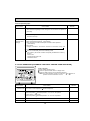
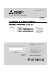
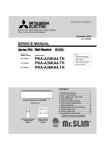
7-1-1. Thermistor
<Thermistor characteristic graph>
< Thermistor for lower temperature >
50
Room temperature thermistor (TH21)
Liquid pipe temperature thermistor (TH22)
Gas pipe temperature thermistor (TH23) (TH24)
Thermistor for
lower temperature
Rt=15exp { 3480(
30°F
50°F
70°F
80°F
90°F
100°F
15.8kΩ
9.6kΩ
6.0kΩ
4.8kΩ
3.9kΩ
3.2kΩ
1
273+(t-32)/1.8
Resistance (kΩ)
Thermistor R0=15kΩ ± 3%
Fixed number of B=3480 ± 2%
40
1 )}
273
30
20
10
0
-20
0
20
40
60
80
Temperature (°F)
100
120
7-1-2. Liner expansion valve
Operation summary of the linear expansion valve
• Linear expansion valve open/close through stepping motor after receiving the pulse signal from the indoor controller board.
• Valve position can be changed in proportion to the number of pulse signals.
Controller board
<Connection between the indoor controller board and the linear expansion valve>
DC12V
Brown
6
Red
5
Blue
4
Φ4
Φ3
Orange
3
Φ3
Φ2
Yellow
2
Φ2
Φ1
White
1
Φ1
Linear expansion valve
4
M
1
White Red
5
6
2
3
Orange
Blue
Brown
Yellow
Φ4
Connector(CN60)
14
Drive circuit
<Output pulse signal and the valve operation>
Output
Output
(Phase)
1
ON
ON
OFF
OFF
[1
[2
[3
[4
2
OFF
ON
ON
OFF
3
OFF
OFF
ON
ON
4
ON
OFF
OFF
ON
Linear expansion valve operation
Note:
• When linear expansion valve operation stops, all output phase
become OFF.
• At phase interruption or when phase does not shift in order, motor
does not rotate smoothly and motor will lock and vibrate.
• When the switch is turned on, 2200 pulse closing valve signal will
be sent till it goes to point in order to define the valve position.
Open
C
D
Valve position (capacity)
Closing a valve : 1 → 2 → 3 → 4 → 1
Opening a valve : 4 → 3 → 2 → 1 → 4
The output pulse shifts in above order.
• When the valve moves smoothly, there is no sound or vibration
occurring from the linear expansion valves, however, when the
pulse number moves from to or when the valve is locked,
more sound can be heard than in a normal situation.
• Sound can be detected by placing the ear against the screw driver
handle while putting the screw driver tip to the linear expansion
valve.
Close
Open
Outdoor unit R410A model : 1400 pulse
Outdoor unit R22 model
: 2000 pulse
Opening a valve all the way
A
E
Close
B
Pulse number
Extra tightening (200~800 pulse)
Trouble shooting
Check points
Symptom
Countermeasures
Operation circuit
failure of the micro
processor
Disconnect the connector on the controller board, then con- Exchange the indoor connect LED for checking.
troller board at drive circuit
6
5
failure.
4
3
2
1
1kΩ LED
When power is turned on, pulse signals will be output for 10
seconds. There must be some defects in the operation circuit
if the LED does not light while the signals are output or keeps
lighting even after the signals stop.
Linear expansion
valve mechanism is
locked.
Motor will idle and make a ticking noise when the motor is
operated while the linear expansion valve is locked.
This ticking sound is the sign of the abnormality.
Exchange the linear expansion valve.
Short or breakage
Measure the resistance between each coil (white-red, yellow- Exchange the linear expanof the motor coil of
brown, orange-red, blue-brown) using a tester. It is normal if sion valve.
the linear expansion the resistance is in the range of 200Ω ±10%.
valve
Valve does not close To check the linear expansion valve, operate the indoor unit If large amount of refrigercompletely.
in fan mode and at the same time operate other indoor units ant is leaked, exchange
the linear expansion valve.
in cooling mode, then check the pipe temperature <liquid
pipe temperature> of the indoor unit by the
outdoor multi controller board operation
monitor. During fan operation, linear expansion valve is closed completely and if there
Thermistor
(Liquid pipe) is any leaking, detecting temperature of
the thermistor will go lower. If the detected
Linear
temperature is much lower than the temexpansion
valve
perature indicated in the remote controller,
it means the valve is not closed all the way.
It is not necessary to exchange the linear expansion valve, if
the leakage is small and not affecting normal operation.
Wrong connection
of the connector or
contact failure
Check the color of lead wire and missing terminal of the con- Disconnect the connector
nector.
at the controller board,
then check the continuity.
15
7-1-3. DC Fan motor (fan motor/indoor controller circuit board)
Check method of DC fan motor (fan motor/indoor controller circuit board)
Notes
· High voltage is applied to the connecter (CNMF) for the fan motor. Pay attention to the service.
· Do not pull out the connector (CNMF) for the motor with the power supply on.
(It causes trouble of the indoor controller circuit board and fan motor.)
Self check
Symptom : The indoor fan cannot turn around.
Wiring contact check
Contact of fan motor connector (CNMF)
Is there contact failure?
Wiring recovery
Yes
No
Power supply check (Remove the connector (CNMF))
Measure the voltage in the indoor controller circuit board.
TEST POINT : VDC (between 1 (+) and 3 (-) of the fan connector): VDC DC294~325V
TEST POINT : VCC (between 4 (+) and 3 (-) of the fan connector): VCC DC15V
Is the voltage normal?
Indoor controller board fuse check
No
No
Is the fuse normal?
Replace the fuse
Yes
OK
Check the operation
Yes
Sensor signal check
Measure the voltage between CNMF and
DC 0V
and DC 15V in the indoor controller circuit board.
No
Does the voltage repeat
DC 0V and DC 15V?
NG
Replace indoor controller board.
OK
Check the operation
END
NG
Replace the fan motor
Yes
Replace indoor
controller board
Replace the fan motor
OK
OK
Check the operation
END
Check the operation
NG
NG
Replace the fan motor.
Replace indoor controller board.
16
END
END
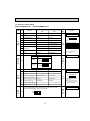
7-2. Function of Dip switch
PKFY-P24NKMU-E.TH
PKFY-P30NKMU-E.TH
Switch Pole
Operation by switch
Function
ON
OFF
1
Thermistor<Room temperature>
position
Built-in remote controller
Indoor unit
2
Filter clogging detection
Provide
Not provide
3
Filter cleaning sign
4
Fresh air intake
SW1
5
Mode
selection 6
7
Remarks
Address board
<Initial setting>
ON
OFF
2,500 hr
100 hr
Not effective
Not effective
1 2 3 4 5 6 7 8 9 10
+2
Switching remote controller display Thermo ON signal indication Fan output indication
Fan operation at Heating mode Thermo ON operation at
heating mode
Humidifier control
Extra low +1
8
Air flow set in case of heat Low +1
thermo OFF
Setting air flow +1
9
Auto restart function
Effective
Not effective
Power ON/OFF by breaker Effective
Not effective
10
Effective
timing
P24
P30
Under
suspension
ON
OFF
SW1-7 SW1-8 Fan speed
OFF OFF Extra low
ON
OFF Low
OFF
ON Setting air flow
ON
ON Stop
Depends on SW1-7
+2 It is impossible to intake
the fresh air.
Indoor controller board
SW2
Models
SW2
Capacity
1~6
code
switch
NOTE:
+1
Before
power
supply
ON
123456
ON
OFF
123456
1
Heat pump/Cool only
2
Not used
—
—
3
Not used
—
—
SW3 4
Function
selection 5
6
Cooling only
Heat pump
Vane horizontal angle
Second setting +1
First setting
Changing the opening of linear
expansion valve during thermo OFF
Effective
Not effective
Heating 4 degree up
Not effective
Effective
7
Target superheat setting +2
—
—
8
Target subcool
—
—
+2
In case of replacing the indoor controller board, make sure to set the
switch to the initial setting, which is shown below.
SW4
Model 1~4
selection
ON
OFF
1 2 3 4
17
Indoor controller board
<Initial setting>
Under
suspension
ON
OFF
1 2 3 4 5 6 7 8
+1 Second setting is same as
first setting.
+2 Please do not use SW3-7,8
as trouble might be caused
by the usage condition.
Indoor controller board
Before
power
supply
ON
1
CDE
AB
789
Address board
<Initial setting>
SW14
CDE
AB
F01
789
Rotary switch
Before
power
supply
ON
23
Jumper
90 1
• To operate each indoor unit by each remote controller when installed 2 indoor
units or more are near, Pair No. setting is necessary.
Pair No. setting is available with the 4 patterns (Setting patterns A to D).
.
Make setting for J41, J42 of indoor controller board and the Pair No. of
wireless remote controller.
• You may not set it when operating it by one remote controller.
Setting for indoor unit
Cut jumper wire J41, J42 on the indoor controller board according to the
table below.
Wireless remote controller pair number:
Setting operation
Under
1. Press the SET button (using a pointed implement). Check that the
operation
remote controller's display has stopped before continuing.
or
MODEL SELECT flashes, and the model No. (3 digits) appears (steadily-lit).
2. Press the MINUTE button twice. The pair number appears flashing.
suspension
3. Press the temperature
buttons to select the pair number to set.
4. Press the SET button (using a pointed implement). The set pair number is
displayed (steadily-lit) for 3 seconds, then disappears.
Setting pattern
Indoor controller
jumper wire
Pair No. of wireless
remote controller
J41
J42
0
—
—
A
Initial setting
1
—
—
Cut
B
2
—
Cut
—
C
3
—
Cut
Cut
D
Pair No.4-9 of wireless remote controller is setting pattern D.
18
45 6
Wireless
remote
controller
Pair No.
How to set branch numbers SW14 (Series R2 only)
Match the indoor unit’s refrigerant pipe with
the BC controller’s end connection number.
Remain other than series R2 at "0".
SW11
90 1
23
J41, J42
45 6
SW14
Branch
No.
Setting
23
F01
SW12
23
SW14
<Initial setting>
78
45 6
45 6
10
Address board
How to set addresses
Example : If address is "3", remain SW12
(for over 10) at "0", and match SW11 (for 1 to 9)
with "3".
78
78
78
23
Rotary Switch
90 1
45 6
SW11
90 1
Remarks
45 6
SW12
23
SW11
1s digit
address
setting
SW12
10ths digit
address
setting
Effective
timing
Operation by switch
Switch
<Initial setting>
Pattern A
Pair No.
MODEL SELECT
FAN
AUTO STOP
VANE
AUTO START
CHECK LOUVER
SET
h
min
TEST RUN
SET button
Temperature
button
TEMP
ON/OFF
MODE
Model No.
RESET
CLOCK
Minute
button
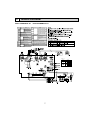
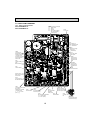
7-3. TEST POINT DIAGRAM
7-3-1. Indoor controller board
PKFY-P24NKMU-E.TH
PKFY-P30NKMU-E.TH
CNMF
Connect to the fan motor (MF)
1-3 : DC294~325V
4-3 : DC15V
5-3 : DC0~6V
6-3 : DC0 or DC15V (Stop)
DC7.5V (Operation)
(12VDC pluse)
FUSE
3.15A 250V
CND
Power supply for
indoor controller board
1-3 : 208/230VAC
LED1
Main power supply
(Indoor unit :
208/230VAC)
CN2M
Connect to the
terminal block (TB5)
(M-NET transmission
connecting wire)
24-30VDC (non-polar)
Power supply from
outdoor unit
CN151
Vane motor output
12VDC pluse
CNRU
Connect to the
wireless remote
controller board
(W.B)
SW2
Capacity setting
LDSWE(A)
Connect to the
wireless remote
controller board
(S.B)
SW4
Model selection
SW3
Function setting
CN52
Remote indicator
Jumper wire J41, J42
Pair No. setting for wireless
remote controller
LED2
Power supply for
MA-Remote controller
CN3A
Connected to the termial
block (TB15)
(MA-Remote controller
connecting wire)
1 - 3 : 8.7-13V DC
(Pin1 (+))
CN32
Remote switch
CN2G
Pipe temperature
thermistor
Gas2 (TH24)
CN20
Room temperature
thermistor (TH21)
CN44
Pipe temperature thermistor
1-2 : Liquid (TH22)
3-4 : Gas1 (TH23)
19
CN60
Liner expansion
valve (LEV) output
12VDC pluse output
CN24
External heater
CN51
Centrally controlled
LD SWE (B)
Connect to the indoor
controller board (I.B)
7-3-2. Wireless remote controller board
PKFY-P24NKMU-E.TH
PKFY-P30NKMU-E.TH
LD101
Connect to the
indoor controller
board (I.B)
7-3-3. Address board
PKFY-P24NKMU-E.TH
PKFY-P30NKMU-E.TH
SW1
Function setting
1 2 3 4 5 6 7 8 9 10
BCD
78
4 56
78
789A
4 56
SW12
SW11
Address setting
10ths DIGIT
Address setting
1s DIGIT
3456
EF0 12
90 1
23
23
90 1
SW14
Branch No.
20
8
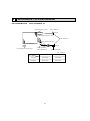
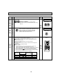
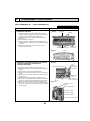
DISASSEMBLY PROCEDURE
PKFY-P24NKMU-E.TH
PKFY-P30NKMU-E.TH
Be careful when removing heavy parts.
OPERATION PROCEDURE
PHOTOS & ILLUSTRATIONS
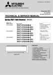
1. REMOVING THE PANEL
Photo 1
Front grille
Screws
(1) Press and unlock the knobs on both sides of the front
grille and lift the front grille until it is level. Pull the hinges
forward to remove the front grille. (See Photo 1)
(2) Remove 3 screw caps of the panel. Remove 5 screws.
(See Photo 1)
(3) Unfix 3 hooks. (See Figure 1)
(4) Hold the lower part of both ends of the panel and pull it
slightly toward you, and then remove the panel by pushing
it upward.
(5) Remove the screw of the corner box. (See Photo 1)
Remove the corner box.
Screws and screw caps
Figure 1
2. REMOVING THE ADDRESS BOARD, THE INDOOR
CONTROLLER BOARD, THE WIRELESS
CONTROLLER BOARD
Hooks
Photo 2
Hook
Screw of address board case
(1) Remove the panel and the corner box. (Refer to 1.)
(2) Remove the screw and hook of address board case. (See
Photo 2)
(3) Disconnect the connectors of address board.
(4) Remove the front and side electrical box covers (each 1
screw).
(5) Disconnect the connectors on the indoor controller board.
(See Photo 3)
(6) Remove the switch board holder and open the cover.
(7) Pull out the indoor controller board toward you then remove
the indoor controller board and switch board. (See Photo 3)
(8) Remove the holder of wireless remote controller board.
(9) Disconnect the connector of wireless remote controller
board and remove the wireless remote controller board
from the holder.
Screw of the
corner box
Screw of
electrical box
cover (side)
Switch board
holder
Water Cut
Screw of electrical box cover Holder of wireless
remote controller board
(Front)
Photo 3
Electrical box cover
(Front)
Indoor controller board
Terminal block (TB2)
Terminal block (TB5)
Terminal block (TB15)
Room temp. thermistor (TH21)
21
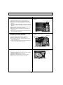
OPERATION PROCEDURE
PHOTOS
3. REMOVING THE ELECTRICAL BOX
Photo 4
Connect for ground
(1) Remove the panel and the corner box. (Refer to 1.)
(2) Remove the screw and hook of address board case.
(3) Remove the front and side electrical box covers (each 1
screw).
(4) Remove the transmission wiring of TB5, the power supply wiring of TB2 and the wiring of MA-remote controller
(TB15).
(5) Disconnect the connectors on the indoor controller board.
(6) Disconnect the connector for ground wire.
(7) Remove the screw on lower side of the electrical box.
(See Photo 5)
(8) Push up the upper fixture catch to remove the box, then
remove it from the box fixture.
Fixture
Electrical box
4. REMOVING THE NOZZLE ASSEMBLY (with VANE
and VANE MOTOR) AND DRAIN HOSE
Photo 5
(see the bottom)
Vane motor
(1) Remove the panel and corner box. (Refer to 1.)
(2) Remove the electrical box covers. (Refer to 2.)
(3) Disconnect the vane motor connector (CN151) on the
indoor controller board.
(4) Pull out the drain hose from the nozzle assembly, and
remove nozzle assembly. (See Photo 5)
Nozzle assembly
Drain hose
Screw of electrical box
Photo 6
5. REMOVING THE VANE MOTOR
(1) Remove the nozzle assembly. (Refer to 4.)
(2) Remove 2 screws of the vane motor unit cover, and pull
out the vane motor unit.
(3) Remove 2 screws of the vane motor unit.
(4) Remove the vane motor from the vane motor unit.
(5) Disconnect the connector from the vane motor.
Screws of the vane motor unit cover
22
Screws of the vane
motor unit
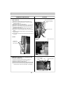
OPERATION PROCEDURE
PHOTOS
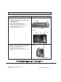
6. REMOVING THE INDOOR FAN MOTOR AND THE
LINE FLOW FAN
Photo 7
Screw of the motor band
(1) Remove the panel and the corner box. (Refer to 1.)
(2) Remove the electrical box (Refer to 2.) and the nozzle
assembly (Refer to 3.).
(3) Remove the water cut. (See Photo 2)
(4) Remove the screw fixing the line flow fan. (See Photo 8)
(5) Remove 5 screws fixing the motor bed. (See Photo 7)
(6) Remove the lead wire of pipe thermistor from the hook of
motor bed. (See Photo 7)
(7) Remove the screw fixing motor band. (See Photo 7)
(8) Remove the motor bed together with fan motor and motor
band.
(9) Remove 3 screws fixing the left side of the heat exchanger.
(See Photo 9)
(10) Lift the heat exchanger, and pull out the line flow fan to the
lower-left.
Lead wire of pipe thermistor
Screws of the motor
bed
Photo 9
Screw of the line flow
fan
Photo 8
Screws of the
left side of the
heat exchanger
7. REMOVING THE LIQUID PIPE THERMISTOR AND
GAS PIPE THERMISTOR
(1)
(2)
(3)
(4)
(5)
Remove the panel and the corner box. (Refer to 1)
Remove the electrical box covers. (Refer to 2.)
Remove the water cut. (See Photo 2)
Remove the liquid pipe thermistor and gas pipe thermistors.
Disconnect the connector (CN44) (CN2G) on the indoor
controller board. (TH22 and TH23/CN44, TH24/CN2G)
Photo 10
Gas pipe thermistor
(TH23) (TH24)
LEV
Connect for ground
Liquid pipe thermistor (TH22)
23
OPERATION PROCEDURE
8. REMOVING THE HEAT EXCHANGER AND LEV
(1) Remove the panel and the corner box. (Refer to 1.)
(2) Remove the electrical box (Refer to 3.) and the nozzle
assembly (Refer to 4.).
(3) Remove the water cut.
(4) Remove the pipe thermistors (Refer to 7.).
(5) Disconnect the connector (CN60) on the indoor controller
board and the connector for ground wire.
(6) Remove 3 screws fixing the left side of the heat
exchanger. (See Photo 9)
(7) Remove the heat exchanger with LEV.
PHOTOS
Photo 11
Heat exchanger
LEV
Water Cut
Photo 12
Heat exchanger
9. REMOVING THE ROOM TEMPERATURE THERMISTOR
(1)
(2)
(3)
(4)
LEV
Connect for ground
Indoor controller
board
Photo 13
Remove the panel and corner box. (Refer to 1.)
Remove the electrical box covers.
Remove the room temperature thermistor.
Disconnect the connector (CN20) on the indoor controller
board.
Room temp.
thermistor (TH21)
HEAD OFFICE : TOKYO BLDG., 2-7-3, MARUNOUCHI, CHIYODA-KU TOKYO 100-8310, JAPAN
Copyright 2009 MITSUBISHI ELECTRIC ENGINEERING CO., LTD.
Distributed in May 2009 No. OCH462 PDF 6
Made in Japan
New publication, effective May 2009
Specifications subject to change without notice