1
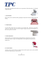
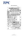
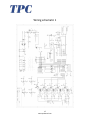
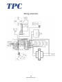
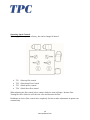
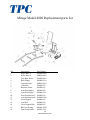
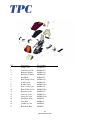
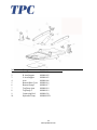
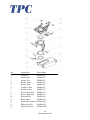
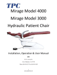
Mirage Model 4000
Mirage Model 3000
Hydraulic Patient Chair
Installation, Operation & User Manual
TPC
851 S. Lawson St.
City of Industry, CA 91748
Phone 626-810-4337 Fax 626-810-4245
1
www.tpcdental.com
REV. 1-1-13
Important! It’s IMPERATIVE that you read
this page before continuing. Failure to do so will
result is wasted time during your installation…
· All patient chairs are pre-wired with low voltage
wiring.
· All patient chairs are pre-wired with touch pad
control cables.
· Patient chairs that are used for “swing mount
delivery”, are pre plumed with tubing to make
your installation process easier.
· If your installation requires the installation of a
touch pad DO-NOT install the upholstery seat
cushion till after your touch pad is installed.
Failure to do so will result in double work.
· If at any time you have questions regarding
your installation please don’t hesitate to
contact TPC toll free @ 800-560-8222 ext 103
or via E-mail @ [email protected]
2
www.tpcdental.com
Table on Contents:
Page
GENERAL INFORMATION
4
Transportation / Storage Information
4
Unpacking instructions
5
Installation and coordination
6
Operation instructions
11
Overview of foot controls
12
Overview of touchpad controls
13
Features
14
Main PCB Board
16
Wiring Schematic 1
17
Adjusting main flow control block
19
Replacement Parts List
20
CLEANING & DISINFECTING GUIDE
24
Warranty
25
TROUBLE SHOOTING GUIDE
26
3
www.tpcdental.com
GENERAL INFORMATION
The dental chair is marked with a
product identification label
including manufacture, serial
number and date of manufacture.
This label is located on the front
lower left cover under the seat
cushion.
The dental chair is marked with a
caution symbol. This label is located
on the front of the dental chair base
next to the main power switch.
The dental chair is marked with a Risk
Class symbol. This label is located on
the front of the dental chair base next
to the main power switch.
The dental chair is marked with a
main electrical grounding point
symbol. This label is located on the
front left side of the dental chair
steel base frame, under the plastic
cover.
The dental chair is marked with a fuse
label symbol. This label is located
under the pump cover on the front
right side of the chair frame.
The fuse is a 6 amp time lag, Fuse, 3AG, 1
1/4" L x 1/4" Dia. (31.8mm x 6.4mm)
Transportation / Storage Information
·
·
·
·
·
·
Do not store the dental chair in temperatures exceeding 130 degrees.
Do not store the dental chair on its side. Always store upright on pallet.
Do not stack more than 5 packaged chairs at a time on top of each other.
Use approved pallet jack or forklift to move the dental chair.
Do not attempt to move stacked dental chairs.
Only store the dental chair in dry cool place.
4
www.tpcdental.com
Mirage Model 4000 unpacking instructions
Place the chair carton close to the
planned area that you wish to install the
dental chair. Do not turn the carton on its
side as oil will drain out of the tank
reservoir. Damage may occur if the chair
is tipped over. Remove all the staples
securing the carton to pallet, or cut the
carton just above the staple line, and
remove Carton. Figure 1
Remove the pump cover from the chair
base. To remove the pump cover you
must first remove the three safely screws.
Once screws are removed lift up on the
cover to remove it. Figure 2
Figure 1
Figure 2
Loosen and remove the two packing
screws holding the chair to the pallet.
Figure 3
When lifting the dental chair use extreme
caution. The chair weight is
approximately 310 LBS. Always use at
least two people when attempting to lift
the dental chair. See image below for use
of proper lift points. Never lift the dental
chair via the arm rests.
Figure 3
Upper lift location
Lower lift location
5
www.tpcdental.com
Mirage Model 4000 Installation instructions
Once the chair is in the desired location
remove the 4 bolts shown in the image
to the right. Place the lift bar in a safe
place for future use.
Once the bolts are removed your
backrest bracket should look similar
to the one shown to the right.
Slide the backrest bracket into place. Make sure
when you slide the bracket into place, you don’t
damage the plastic backrest cover by forcing it or
twisting it. You may loosen the screws that attach
the backrest cover to the plate if you would like.
6
www.tpcdental.com
Once the backrest bracket is in place,
the 4 bolt holes should be aligned.
Use the lock washer and bolts from
step 1 to fasten the bracket in place.
Insert and tighten the 4 bolts with the
lock washers in place. Be sure not to
over tighten the bolts
7
www.tpcdental.com
Installing the upholstery
1. Open the bolt package included in your upholstery box.
2. Locate the nuts and bolts shown in figure 1.
3. Attach the nuts to the bolts and place them in the backrest frame as shown in figure 2. Adjust
the nut so that the head of the bolt and the back of the nut are able to slide up and down with
little resistance in the backrest bracket.
4. Once the space is adjusted remove the bolts with the nuts still attached and try to keep the
spacing the same.
5. Place the bolts into the backrest as shown in figure 3
6. Slide the upholstery into the backrest bracket. Press gently on the seat back cushion side so
that all four bolts align properly within the backrest bracket. Once aligned apply pressure to
the top of the upholstery and lock it into place. Figure 4
Figure 1
Figure 2
Figure 3
8
www.tpcdental.com
Figure 4
1. Take the seat cushion out and place it upholstery side down.
2. Locate the rivet insert holes to mount the seat cushion hardware.
3. Use the Allen screws, lock washers and washers shown in figure 1 to attach the s-bracket shown
in figure 2 to the upholstery
4. Mount the s bracket as shown in figure 3.
5. Attach the two Allen screws (included) to the chair seat cushion frame shown in figure 3.
Figure 2
Figure 1
Incorrect: Mounting the S-bracket this
way will damage the upholstery
frame. Damage will occur. Notice that
the bracket is hanging over the
upholstery.
Correct: Notice that the S-bracket is
flush with the end of the upholstery.
Figure 3
9
www.tpcdental.com
1. Insert the chair seat cushion into the seat pan bracket notch shown in figure 1. You will notice
that the seat pan is notched so that the bracket can slide into place and not move from left to
right.
2. locate the Allen screws , lock washer and washers shown in figure 2
3. Once the bracket is securely in place you may fasten the toe of the upholstery to the frame as
shown in figure 3.
4. Attach the headrest upholstery to the headrest stem as shown in figure 4. Be sure to use the
counter sunk Phillip head screws shown in figure 5. Don’t over tighten the screws.
Figure 1.1
Figure 1
Figure 2
Figure 3
Figure 5
Figure 4
10
www.tpcdental.com
Mirage Model 4000 operation instructions
Please take time out to read the features and to familiarize yourself with the chair.
11
www.tpcdental.com
Overview of foot control operations
1. Seat Height Adjustments
-
To raise, press down on upper area of the foot control disc.
To lower, press down on the lower area of the foot control disc.
2. Backrest Adjustments
-
To raise, press down on right side of the foot control disc.
To recline, press down on left side of foot control disc.
3. Preset Operation
-
Momentarily press pre set switch (#1, or #2) on the foot control.
4. Adjusting Preset
The preset mode is factory installed but can be changed at your convenience as shown below.
Set backrest angle and seat height to desired position using the foot control. Press and hold the preset
position 1 or 2 on foot control. You will hear an initial tone when the button is pressed. After about 5
seconds you will hear a confirm tone. Now that preset position is programmed.
5. Automatic Return
Momentarily press 0 switch on foot control to activate chair to return to normal position.
6. Last position L/P
When the LP button is pressed the backrest will move to its last position that it was placed.
Chair Base up
Preset 1
Preset 2
Chair back down
Chair Back UP
Auto Return
Last Position
Chair Base down
12
www.tpcdental.com
Overview of optional touchpad controls
1. Seat Height Adjustments
-
To raise, press down on upper area of touch pad.
To lower, press down on the lower area of touch pad.
2. Backrest Adjustments
-
To raise, press down on right side of touch pad.
To recline, press down on left side of touch pad.
3. Preset Operation
-
Momentarily press pre set switch (#1, #2or #3) on touch pad.
4. Adjusting Preset
The preset mode is factory installed but can be changed at your convenience as shown below.
Set backrest angle and seat height to desired position using the touch pad. Press preset position 1, 2 or
3 on touch pad and hold down. You will hear an initial tone. After about 5 seconds you will hear a
confirm tone. Now that preset position is programmed.
5. Automatic Return
Momentarily press 0 switch on foot control to activate chair to return to normal position.
Chair Base up
Chair Back UP
Chair back down
Preset 1,2 and 3
Last Position
Chair Base down
13
www.tpcdental.com
Auto Return
6. Safety Plate
Safety plate is provided below base link cover to stop motion of chair when object is accidentally
caught underneath.
7. Armrest Rotation
Either armrest can be rotated outward by grasping the end portion of armrest, pulling upward and
turning.
8. Chair Rotation
To swivel chair, release lock lever located on rear of dental chair. Pull lever to the right to
release lock. This allows chair to swivel to the right (30 degrees) and to the left (30 degrees). To
lock swivel, pull lever to the left.
9. Headrest Adjustments
Height of headrest can be adjusted simply by pulling headrest up or down due to friction mount
incorporated in backrest. Angle of articulating headrest can be changed by releasing slide bar on
headrest back.
10. Automatic Motion
Automatic motion activated either by automatic return switch or preset switch, can be cancelled
at any time by depressing any control switches.
14
www.tpcdental.com
Motion Limit Controls
Function
The Mirage Hydraulic Patient Chair does not use conventional mechanical or mercury limit
switches. Motion of the chair base and backrest move variable resistances (potentiometers)
making it possible for the control circuitry to continuously know the exact position of the base
and backrest, not only when they hit the end of their travel. Adjustments for all four actions (seat
raise/ lower, backrest raise/recline) are located on the control PCB.
Adjustment
To set a specific limit for the mirage operatory chair, perform the following instructions. Remove
the pump cover from the chair. Locate the slider switch labeled S1. The switch is located on the
lower left corner of the main PCB board. This will put the chair into manual mode. Use the touch
pad or foot control to move the chair to the desired position. See below for detailed instructions
on setting each limit. A diagram of the PCB board is on the following page.
Seat Lower Limit
Using the manual controls, set seat height to the position where the lower limit is set. Press Lift
DO on the main PCB board to program. Reset the Slide Switch on PCB to Normal. Use the touch
pad or foot control to move the chair up, and then use the lift down on the touch pad or foot
control to verify that the new limit is set.
Seat Height Limit
Using the manual controls raise the seat height fully. At the physical top of travel, the motor will
continue to run, but upward motion will stop (oil bypass channel has opened in cylinder). Lower
the seat height slightly from this point, and press LIFT UP button on Control PCB. Reset the
Slide Switch on PCB board to Normal. Then use the touch pad or foot control to lower the chair,
raise the chair and verify the desired height limit is set.
Backrest Recline Limit
Using the manual controls, Recline the backrest fully. Raise the backrest slightly from this point,
and press the BACK DN button on the main PCB board. Reset the Slide Switch on PCB board to
Normal. Then raise the back rest and then lower it to verify the desired setting is set.
Backrest up Limit
Using the manual controls, raise the backrest fully. Then lower the backrest slightly from this
point. Press the backup button on the main PCB board. Reset the Slide Switch on PCB board to
Normal. Then use the foot control disc to lower the backrest. Raise the backrest to verify the
desired height limit is set.
15
www.tpcdental.com
Main PCB Board
16
www.tpcdental.com
Wiring schematic 1
17
www.tpcdental.com
Wiring schematic
18
www.tpcdental.com
Operating Speed Controls
Operating speeds are preset at factory, but can be changed if desired.
·
·
·
·
TV1
TV2
TV3
TV4
= Base up flow control
= Base down Flow Control
= Back up flow control
= Back down flow control
When adjusting the flow control valves counter clockwise turns will open / increase flow.
Turning the valve clockwise will close the valve and decrease the flow.
Don’t open or close a flow control valve completely. Its best to make adjustments in quarter turn
rotations only.
19
www.tpcdental.com
Mirage Model 4000 Replacement parts list
16
NO.
1
2
3
4
5
6
7
8
9
10
11
12
13
14
15
16
Description
Part Number
Roller Base L
M4000-008A
Roller Base R
M4000-009A
Cast Back Roller
M4000-010A
Back Flange
M4000-011A
Cushion Frame
M4000-012A
U Bracket
M4000-022
Backrest Frame
M4000-025
Arm Rest flange 1
M4000-028
Arm Rest Flange 2 M4000-28A
Arm Rest Bracket L M4000-029
Arm Rest Bracket R M4000-029A
Cross Support
M4000-041
Arm Rest
M4000-042
Cross Support Bolt M4000-043
%5&DVW%HDULQJ04000-12ZZ
6HDW)UDPH5ROOHU
M4000-1215
20
www.tpcdental.com
NO.
1
2
3
4
5
6
7
8
9
10
11
12
13
14
15
16
17
Description
Pump Cover
Cushion cover/B
Bottom Cushion
Backrest Cushion
Head Rest
Rear Flange Cover
L Side Cover
R Side Cover
Rear L side Cover
Rear R Side Cover
Backrest Cover
Lower L Cover
Lower R Cover
Head Rest Stem
Cast Base
Cantilever Cast
Back Rest Base
Part Number
M4000-015
M4000-023
M4000-024
M4000-026
M4000-027
M4000-030
M4000-031
M4000-031A
M4000-032
M4000-032A
M4000-033
M4000-034
M4000-034A
M4000-01
M4000-A
M4000-B
M4000-C
21
www.tpcdental.com
NO.
1
2
3
4
5
6
7
8
9
10
Description
Cast Base
R Arm Support
L Arm Support
Arm
Bottom Base Cover
Bottom Pump T
Top Pump Arm
Top Pump T
Connecting Rod
Hydraulic Pump
Part Number
M4000-001
M4000-002
M4000-003
M4000-006
M4000-016
M4000-017
M4000-018
M4000-019
M4000-036
M4000-HYD
22
www.tpcdental.com
NO.
1
2
3
4
5
6
7
8
9
10
11
12
13
14
Description
Part Number
Cantilever
M4000-004
Rotator Base
M4000-005
Rotator Top
M4000-007
Rotator Insert
M4000-020
Break Clamp
M4000-021
Cantilever Rod
M4000-035
Cantilever Pins
M4000-037
Break Clamp Rod
M4000-038
Break Clamp Arm
M4000-039
Hydraulic Pin
M4000-040
Bracket Base
M4000-044
Insert Base Connector M4000-045
Rollers Seat Pan
M4000-RSP
Hydraulic Piston
M4000-HYD
23
www.tpcdental.com
Mirage Hydraulic Patient Chair – Care and Maintenance
No maintenance is required except normal care and cleaning.
Clean vinyl upholstery and plastic components with mild soap and water.
Barrier covers should be used on chairs for asepsis.
Surface disinfecting chemical will eventually cause some discoloring of upholstery.
Suggested Disinfectant Application
Clean dirt and stains with mild soap and water.
Moisten an applicator with disinfectant; mildly wipe the material with the disinfectant.
Do not allow the disinfectant to soak in or dry on the surface; wipe off with soap and water.
PLEASE KEEP LIQUIDS AWAY FROM ELECTRICAL CONNECTIONS!
Most electrical control switches ARE NOT hermetically sealed.
When a switch gets wet, it can self-activate, or perhaps short out and damage other system
components. Keep switches dry. Avoid costly equipment damage or failure. Avoid downtime by
following these guidelines:
Please DO NOT spray disinfectants directly AT OR INTO electrical switches and controls.
Simply spray these solutions onto a cloth and wipe down the control surfaces. Be careful not to
saturate the cloth.
·
Any action not recommended by the manufacture may cause risk of injury or shock!
FOR ADDITIONAL INFORMATION CONTACT YOUR TPC DEALER
24
www.tpcdental.com
TPC 5 YEAR LIMITED WARRANTY
Warranty Information
All of our products sold are guaranteed to be free from defects in workmanship and materials for
a 1 year from date of purchase, unless otherwise stated. TPC will repair or replace any defective
part at no charge. TPC will not be responsible for labor charges or shipping charges to / from the
TPC facility. This guarantee does not cover normal wear or stains on surface finish. The
guarantee does not cover damage resulting from improper installation, misuse or accidents
incurred in shipping and handling. All claims against the freight carrier must be initiated at the
time the damaged items are received. The claim is the responsibility of the customer. We are
improving our products on a continuous basis. We reserve the right to make modifications
without the need for prior notification and are not obliged to modify previously manufactured
items. Main hydraulic pumps and hydraulic parts are covered under the 5 year warranty. Main
chair PCB, transformer and solenoids are also covered under a 5 year warranty. Major cast
components are covered under the TPC limited 5 year warranty. Upholstery, arm rests and any
plastic components are covered under a 1 year warranty. Only authorized service technicians
should attempt to service TPC equipment. Service performed by any unauthorized technicians
may result in a voided warranty.
25
www.tpcdental.com
Mirage Model 4000 Troubleshooting
Problem
Dental Chair does not move
up or down. Chair makes no
sound.
Cause
No power
Blown fuse
Power switch off
Blown transformer
Dental Chair will not move,
but makes a beep sound when
controls are pressed
Safety switch plate
Limit switch memory erased
Chair makes noise when
motor is running. Squealing
Dental Chair does not go low
or high enough
Unable to program pre set
position 1, 2 and 3
Chair is low on hydraulic fluid
When I auto return the chair
with button 0 the chair goes
down and then raises about 3”
once its down
My chair is on but there is no
control out of the touch pad
My head rest does not stay in
the position that I put it in
Chair arm rest moves very
easley.
Safety switch is being tripped.
Program limits
Chair is in program mode and
not operational mode.
Touch pad is not connected
Touch pad is burnt out
Set screws in backrest are
loose.
Screw is loose that holds
assembly together
Solution
Check power source
Check fuse
Check power switch
Check transformer voltage
12vac
Check safety plate
Re-program limit switches.
Refer to motions of limit
controls
Re-fill hydraulic reservoir
Re program limit switch
settings
Put chair in normal operation
mode. Change SW1 on Main
PCB
Check safety switch and area
around chair base.
Connect touch pad
Replace touch pad
Tighten set screws
Tighten screw
Mirage Model 4000 Don’ts
·
·
·
·
·
·
Don’t exceed the minimum weight capacity of 650 lbs or damage may occur.
Don’t let more than one patient sit in the chair at one time.
Don’t stand anywhere on the dental chair.
Don’t operate the dental chair around any flammable liquids.
Don’t exceed the maximum mode of operation time “3 min”.
Keep liquids away from all electrical components.
26
www.tpcdental.com