1
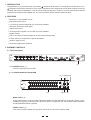
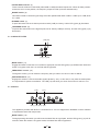
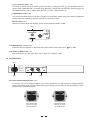
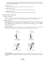
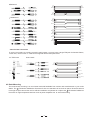
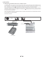
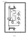
User's Manual
ALTO MONITOR
PA/MONITOR
PROCESSOR
R
LTO
www.altoproaudio.com
Version 1.4 September 2005
English
Fuse
SAFETY RELATED SYMBOLS
To prevent fire and damage to the product, use only
the recommended fuse type as indicated in this
manual. Do not short-circuit the fuse holder. Before
replacing the fuse, make sure that the product is
OFF and disconnected from the AC outlet.
CAUTION
RISK OF ELECTRIC SHOCK
DO NOT OPEN
This symbol, wherever used, alerts you to the presence of un-insulated and dangerous voltages within the product enclosure. These are voltages that
may be sufficient to constitute the risk of electric
shock or death.
Protective Ground
Before turning the product ON, make sure that it is
connected to Ground. This is to prevent the risk of
electric shock.
This symbol, wherever used, alerts you to important operating and maintenance instructions.
Please read.
Never cut internal or external Ground wires. Likewise,
never remove Ground wiring from the Protective
Ground Terminal.
Protective Ground Terminal
Operating Conditions
AC mains (Alternating Current)
Always install in accordance with the manufacturer's
instructions.
Hazardous Live Terminal
ON:
To avoid the risk of electric shock and damage, do
not subject this product to any liquid/rain or moisture.
Do not use this product when in close proximity to
water.
Denotes the product is turned on.
OFF: Denotes the product is turned off.
WARNING
Do not install this product near any direct heat source.
Describes precautions that should be observed to
prevent the possibility of death or injury to the user.
Do not block areas of ventilation. Failure to do so
could result in fire.
CAUTION
Keep product away from naked flames.
Describes precautions that should be observed to
prevent damage to the product.
IMPORTANT SAFETY INSTRUCTIONS
Read these instructions
Disposing of this product should not be
placed in municipal waste and should be
Separate collection.
Follow all instructions
Keep these instructions. Do not discard.
Heed all warnings.
WARNING
Only use attachments/accessories specified by the
manufacturer.
Power Supply
Ensure that the mains source voltage (AC outlet)
matches the voltage rating of the product. Failure
to do so could result in damage to the product and
possibly the user.
Power Cord and Plug
Do not tamper with the power cord or plug. These are
designed for your safety.
Unplug the product before electrical storms occur
and when unused for long periods of time to reduce
the risk of electric shock or fire.
Do not remove Ground connections!
External Connection
Protect the power cord and plug from any physical
stress to avoid risk of electric shock.
If the plug does not fit your AC outlet seek advice from
a qualified electrician.
Always use proper ready-made insulated mains
cabling (power cord). Failure to do so could result
in shock/death or fire. If in doubt, seek advice from
a registered electrician.
Do not place heavy objects on the power cord. This
could cause electric shock or fire.
Cleaning
When required, either blow off dust from the product
or use a dry cloth.
Do Not Remove Any Covers
Within the product are areas where high voltages
may present. To reduce the risk of electric shock do
not remove any covers unless the AC mains power
cord is removed.
Do not use any solvents such as Benzol or Alcohol.
For safety, keep product clean and free from dust.
Servicing
Covers should be removed by qualified service
personnel only.
No user serviceable parts inside.
Refer all servicing to qualified service personnel only.
Do not perform any servicing other than those instructions contained within the User's Manual.
1
PREFACE
Dear Customer:
Thanks for choosing LTO Monitor PA/Monitor Processor and thanks for choosing one of the results of
AUDIOTEAM job and researches.
LTO
For our LTO AUDIO TEAM, music and sound are more than a job...are first of all passion and let us say...our
obsession!
We have been designing professional audio products for a long time in cooperation with some of the major brands
in the world in the audio field.
The LTO line presents unparalleled analogue and digital products made by Musicians for Musicians in our R&D
Centres in Italy, Netherlands, United Kingdom and Taiwan. The core of our digital audio products is a sophisticated
DSP (Digital sound processor) and a large range of state of the art algorithms which have been developed by our
Software Team for the last 7 years.
Because we are convinced you are the most important member of LTO AUDIO TEAM and the one confirming
the quality of our job, we would like to share with you our work and our dreams, pay attention to your suggestions
and your comments.
Following this idea we create our products and we will create the new ones! From our side, we guarantee you
and we will guarantee you also in future the best quality, and the best fruits of our continuous researches and the
best prices.
Our LTO Monitor PA/Monitor Processor is based on many years of experience and is designed to provide a precise
equalization to studio engineer and sound contractor. It can be used to modify the frequency "contour" of a sound,
eliminate the unwanted frequencies and suppress the feedback well.
Nothing else to add, but that we would like to thank all the people that made the LTO Monitor PA/Monitor
Processor a reality available to our customers, thank our designers and all LTO staff, there to make possible
the realization of products containing our idea of music and sound and there to support you, our customers,
in the best way, conscious that you are our best richness.
Thank you very much.
LTO AUDIO TEAM
2
TABLE OF CONTENT
1. INTRODUCTION ...................................................................................................................................4
2. FEATURES ...........................................................................................................................................4
3. ELEMENT CONTROLS.........................................................................................................................4
3.1 The Front Panel
3.2 The Rear Panel
4. INSTALLATION & CONNECTION ........................................................................................................7
4.1 Mains Connection
4.2 Audio Connection
- Wiring Configuration
- In Line Connection
- Insert Points Connection
4.3 Rack Mounting
5. APPLICATION..........................................................................................................................................9
5.1 Using your
LTO Monitor PA Processor in a Monitor system
6. TECHNICAL SPECIFICATIONS ..........................................................................................................10
7. BLOCK DIAGRAM ..............................................................................................................................11
8. WARRANTY ........................................................................................................................................12
3
1. INTRODUCTION
Congratulations on your purchasing the very powerful LTO Monitor PA Processor. It is really efficient for PA monitor. Your
LTO Monitor PA Processor is based on many years of experience and is designed to provide studio engineer and sound
contractor with a precise equalization. It can be used to modify the frequency "contour" of a sound, eliminate the unwanted
frequencies and suppress the feedback well. For more information, please read this manual carefully.
2. FEATURES
Mountable in one standard unit 19"
Illuminated power switch
1/4" TRS type jack and balanced XLR connectors available
LED meter (8 LEDs) to read output
Output level control
15 band graphic equalizer, low cut filter and notch available
Bypass function
Low cut and high cut filters available to cancel unwanted frequencies
Inverter switch to compensate for phase cancellation
Variation adjust control
Accurately suppress the feedback
3. ELEMENT CONTROLS
3.1 The Front Panel
OUTPUT LEVEL(dB)
24
12
6
12
6
6
40Hz
18
12
R
0
0
HI-PASS
LOW-PASS
MODE
RANGE
6
12
25
40
63
100
160
250
400
630
1K
1.6K
2.5K
6.3K
4K
10K
16K
6
270
Bypass
ON
6
12
15 BAND GRAPHIC EQUALIZER
LTO MONITOR
MODE
360
400
40
Bypass
ON
FREQUENCY (Hz)
1
3
MODE
15
6
LEVEL
18
INVERTER
25
12
12
0
90
LTO
6
0
6
16KHz
4K
400
FREQUENCY (Hz)
LOW CUT FILTER
10
1
dB
DEPTH
ON
MODE
20
0
20K
2K
2K
200
Bypass
ON
FREQUENCY (Hz)
0
10
1
Û
20
dB
DEPTH
dB
Bypass
ON
MASTER VOL.
NOTCH2
NOTCH1
PA/MONITOR
PROCESSOR
OFF
6
POWER
(1)
3.1.1 POWER switch (1)
Turns the apparatus ON and OFF.
3.1.2 15 BAND GRAPHIC EQUALIZER
(4) (7)(8)(10)(9)
12
6
12
R
6
6
0
0
LTO
12
6
12
25
40
63
100
160
250
400
630
1K
1.6K
2.5K
4K
6.3K
10K
16K
6
40Hz
16KHz
HI-PASS
LOW-PASS
MODE
RANGE
6
LEVEL
Bypass
ON
6
12
15 BAND GRAPHIC EQUALIZER
(5)
(3) (2) (6)
MODE switch (2)
Engage this switch to insert the 15 Band Graphic Equalizer and HI/LOW PASS to signal path, and the corresponding LED (green) (3) will illuminate. When this switch is in bypass mode, the 15 Band Graphic Equalizer
and HI/LOW PASS will be bypassed.
LEVEL control (4)
This control is used to adjust the input level, which can be varied from -6dB to +6dB.
4
FILTER GAIN controls (5)
These controls will boost or attenuate (either 6dB or 12dB) the select frequencies. When all slider potentiometers are set in center position, the frequency response is flat (no boost and attenuate).
RANGE switch (6)
This switch is used to choose the gain range of the filter potentiometer either +6dB or +12dB. Up for +6dB, down
for +12dB.
HI-PASS switch (7)
To press this switch will cut the low frequencies at 40Hz (12dB per octave), and the LED (green) (8) illuminates.
LOW-PASS switch (9)
To press this switch will cut the high frequencies at 16kHz (12dB per octave), and the LED (green) (10)
illuminates.
3.1.3 LOW CUT FILTER
(15)(14)
90
INVERTER
25
270
MODE
15
360
Bypass
ON
FREQUENCY (Hz)
LOW CUT FILTER
(13) (11)(12)
MODE switch (11)
Engage this switch to insert the Low Cut Filter to signal path, and the LED (green) (12) will illuminate. When this
switch is in bypass mode, the Low Cut Filter will be bypassed.
FREQUENCY control (13)
Through this control, you can select the frequency that you want to cut off from 15Hz to 360Hz.
INVERTER switch (14)
Engage this switch to reverse the audio signal's phase by 180 . In this case, it may alter the audio phase
to compensate for phase cancellation. The LED (15) will show you when the function is active or not.
3.1.4 NOTCH
(19)
(17)
MODE
400
40
4K
400
FREQUENCY (Hz)
20
0
10
1
dB
DEPTH
MODE
2K
200
Bypass
ON
20K
2K
FREQUENCY (Hz)
NOTCH1
0
10
1
20
dB
DEPTH
Bypass
ON
NOTCH2
(20) (18) (21) (16)
The apparatus provides with NOTCH 1 and NOTCH 2. You can suppress the feedback via each variation
of separated 2 Notch filter frequencies.
MODE switch (16)
Through pressing this switch you will insert the Notch filter to signal path, and the LED (green) (17) will illuminate. When this switch is in bypass mode, the Notch filter will be bypassed.
5
1/ 10 selection switch (18)
This switch is used to change the selecting range of frequency. Engage the switch ( 1), the adjustable frequency
range is 40Hz- 400Hz (NOTCH 1) or 200Hz- 2kHz (NOTCH 2), and the LED (19) illuminates. Otherwise ( 10), the
adjustable frequency range is 400Hz- 4kHz (NOTCH 1) or 2kHz - 20kHz (NOTCH 2).
FREQUENCY control (20)
This control provides with two frequency ranges. For the details, please refer to the above. Rotate this
knob to control the howling resonance frequency response at room.
DEPTH switch (21)
Rotate this knob to adjust the variation, which can be varied from 0dB to -20dB.
(23)
OUTPUT LEVEL(dB)
18
24
12
6
0
6
12
18
0
LTO MONITOR
1
3
Û
PA/MONITOR
PROCESSOR
ON
OFF
6
dB
POWER
MASTER VOL.
(22)
3.1.5 MASTER VOL. control (22)
Rotate this knob to attenuate or boost the output level, which can be varied from -
dB to +6dB.
3.1.6 OUTPUT LEVEL meter (23)
The meter informs you the output level, with a range from -24dB to +18dB.
3.2 The Rear Panel
(24)
AC INPUT
220-240V
USE ONLY WITH A 250V FUSE
EMPLOYER UNIQUEMENT AVEC
UN FUSIBLE DE 250V
110-120V
95-120V /210-240V 60-50Hz
Rated Power Consumption 8W
FUSE:
TIP/PIN 2
RING/PIN 3
SLEEVE/PIN 1
TIP/PIN 2
RING/PIN 3
SLEEVE/PIN 1
210-240V: T200mAL 250VAC
95-120V: T315mA 250VAC
REPLACE FUSE WITH CORRECT
TYPE ONLY
Apparaten skall anslutas till
jordat uttag nar den ansluts
till ett natverk
(25)
2
J.T.
1
3
OUTPUT
(27)
INPUT
(26)
3.2.1 Fuse Holder/Voltage Selector (24)
You must be sure of the voltage available in your country because this is a dual voltage unit. Voltage operation
can be changed through the fuse protecting the power supply. We recommend that the operation will be
performed by a qualified engineer.
220-240V
110-120V
110-120V
220-240V
THIS IS SET FOR
110V AC TO 120V
AC OPERATION
THIS IS SET FOR
220V AC TO 240V
AC OPERATION
6
Please note the triangular markers on both sides of the fuse holder (see above figure). To change the voltage
pull the fuse holder out, rotate it 180 and push it back again. The operating voltage will be that indicated by
one of the two triangular markers.
3.2.2 AC Inlet (25)
After the correct voltage has been set you can connect the AC plug to the unit.
3.2.3 Input Connectors (26)
Either XLR or unbalanced 1/4" TRS jack input connector is used to input the signal.
3.2.4 Output Connector (27)
Either XLR or unbalanced 1/4" TRS jack output connector is used to output the signal.
4.INSTALLATION & CONNECTION
4.1 Mains Connection
A Main AC cord that meets all the international safety regulations is supplied with your LTO Monitor. Please make
sure of the supply voltage available in your Country before plugging in the power cord into the AC socket.
4.2 Audio Connection
Balanced XLR plus 1/4" TRS connectors are available on your LTO Monitor PA/Monitor Processor. In this way you can
interface your LTO Monitor in several different ways without experiencing any noise or signal loss. You can use your LTO
Monitor with single instruments using the mixers main insert or on the complete mix connecting the LTO Monitor in between
the mixer and the power amplifier.
- Wiring Configuration
Either the 1/4" TRS phone jack or the XLR connector can be wired in balanced and unbalanced modes, which will be
determined by the actual application status, please wire your system as the following wiring examples:
Gnd/Screen
1/4"TRS jack
Unbalanced Input
1/4"TRS jack
Balanced Input
XLR Balanced Input
XLR Unbalanced Input
- In Line Connection
For these applications the
LTO Monitor PA/Monitor Processor provides 1/4" TRS connector and XLR connector
to easily interface with most any professional audio device. Follow the configuration examples below for your particular
connection.
7
Balanced
Tip
Ring
Sleeve
TIP RING SLEEVE
SLEEVE RING TIP
Tip
Ring
Sleeve
1
2
3
1
2
3
Tip
Ring
Sleeve
1
2
3
Tip
Ring
Sleeve
1
2
3
Tip
1
2
3
TIP RING SLEEVE
Unbalanced
TIP RING SLEEVE
Sleeve
TIP SLEEVE
1
2
3
Tip
SLEEVE TIP
TIP SLEEVE
Centre
Screen
Tip
Sleeve
Sleeve
Tip
Ring
Sleeve
Tip
Ring
Sleeve
Tip
Centre
Screen
SLEEVE RING TIP
TIP RING SLEEVE
Sleeve
TIP SLEEVE
Tip
Ring
Sleeve
TIP RING SLEEVE
1
2
3
Centre
Screen
1
2
3
- Insert Points Connection
If you are connecting to a mixing console's main inserts, you may have a single TRS jack for Send & Return,
in this case, use an insert "Y" cable that configured like the examples below.
1/4" TRS insert
Insert Leads
SLEEVE TIP
TIP RING SLEEVE
Tip
Ring
Sleeve
Tip (Send)
Sleeve
Tip (Return)
Sleeve
SLEEVE TIP
1
2(Send)
3
Tip
Ring
Sleeve
TIP RING SLEEVE
Tip
Ring
Sleeve
TIP RING SLEEVE
1
2(Return)
3
Centre(Send)
Screen
Centre(Return)
Screen
4.3 Rack Mounting
The most secure mounting is on a universal rack shelf available from various rack manufactures or your music
dealer. The LTO Monitor PA/Monitor Processor fit into one standard 19" rack unit of space. Be sure that there
is enough air space around the unit for sufficient ventilation and please do not place the LTO Monitor PA/Monitor
Processor on high temperature devices such as power amplifiers etc. to avoid overheating.
8
5. APPLICATION
5.1 Using your
LTO Monitor PA Processor in a Monitor system
In monitor system, how to get the pure and natural sound? How to get the sufficient gain before feedback occurs?
How to eliminate the noise? Many top music engineers and performers have been searching for the solution for a long
time... Fortunately, you own the LTO PA Monitor Processor now, it will help you solve the problems.
In particular circumstance, you need to depend upon the position and distance of the performer or singer, microphone
and monitor speaker to arrange your system. You can use your LTO Monitor as an "in line" processor or use it
for single instrument equalization.
This is one possible configuration of PA Monitor system. Using the multi-channels mixer, accurate Monitor processor,
monitor amplifier and monitor speaker.
The detail is as follows:
AC INPUT
110-120V
95-120V~/210-240V~60-50Hz
Rated Power Consumption 9W
TIP / PIN 2
RING / PIN3
SLEEVE / PIN 1
TIP / PIN 2
RING / PIN3
SLEEVE / PIN 1
220-240V
FUSE:
NEW
210-240V:T200mAL 250VAC
95-120V:T315mA 250VAC
REPLACE FUSE WITH
CORRECT TYPE ONLY
TIDE
NEW
3
2
TIDE
3
1
2
1
INPUT
OUTPUT
Input
AUX Send
MIC level signal
Monitor amp
Monitor speaker
9
6. TECHNICAL SPECIFICATIONS
AUDIO INPUT
Type
Active balanced XLR and 1/4" JACK
Impedance
Balanced: 50kOhm Unbalanced: 25kOhm
Operating level
+4dBu/
Maximum input level
CMRR
Balanced and Unbalanced: +19dBm
>55dB @1kHz
AUDIO OUTPUT
Type
XLR and 1/4" JACK
Impedance
Balanced: 60Ohm Unbalanced: 30Ohm
Maximum output level
+21dBm
SYSTEM SPECIFICATIONS
THD+N%
Noise
Frequency response
0.01% typ. 1kHz, @+4dBu
>-92dBr unweighted 22Hz to 22kHz
10dBV
10Hz to 30kHz,
3dB
Low cut filter
High pass filter
Variable (15Hz to 360Hz)
Low pass filter
16kHz
Notch 1 frequency
400 ~ 4kHz / 40 ~ 400Hz
Notch 2 frequency
200 ~ 2kHz / 2k ~ 20kHz
Notch depth
Variable 0 ~ -20dB
Graphic EQ band separation
2/3 Octave. 1
INDICATORS
Output level
40Hz
15 band
Function switch
8-segment LED display:-24/-18/-12/-6//0//+6/+12/+18dB
LED indicator of every switch
POWER SUPPLY
Main voltages
USA/Canada
95 - 120V ~, 60Hz
Europe
210 - 240V ~, 50Hz
U.K./Australia
240V ~, 50Hz
Power consumption
8W
Fuse
95 -120V: T315mAL 250VAC
210-240V: T200mAL 250VAC
Standard IEC receptacle
Main connection
PHYSICAL
Dimension
Weight
483(W)
194.1(D)
2.8kg
10
44(H)mm
7. BLOCK DIAGRAM
11
8. WARRANTY
1. WARRANTY REGISTRATION CARD
To obtain Warranty Service, the buyer should first fill out and return the enclosed Warranty Registration Card within
10 days of the Purchase Date.
All the information presented in this Warranty Registration Card gives the manufacturer a better understanding of
the sales status, so as to purport a more effective and efficient after-sales warranty service.
Please fill out all the information carefully and genuinely, miswriting or absence of this card will void your warranty
service.
2. RETURN NOTICE
2.1 In case of return for any warranty service, please make sure that the product is well packed in its original shipping
carton, and it can protect your unit from any other extra damage.
2.2 Please provide a copy of your sales receipt or other proof of purchase with the returned machine, and give detail
information about your return address and contact telephone number.
2.3 A brief description of the defect will be appreciated.
2.4 Please prepay all the costs involved in the return shipping, handling and insurance.
3. TERMS AND CONDITIONS
3.1
LTO warrants that this product will be free from any defects in materials and/or workmanship for a period
of 1 year from the purchase date if you have completed the Warranty Registration Card in time.
3.2 The warranty service is only available to the original consumer, who purchased this product directly from the
retail dealer, and it can not be transferred.
3.3 During the warranty service, LTO may repair or replace this product at its own option at no charge to you for
parts or for labor in accordance with the right side of this limited warranty.
3.4 This warranty does not apply to the damages to this product that occurred as the following conditions:
Instead of operating in accordance with the user's manual thoroughly, any abuse or misuse of this product.
Normal tear and wear.
The product has been altered or modified in any way.
Damage which may have been caused either directly or indirectly by another product / force / etc
Abnormal service or repairing by anyone other than the qualified personnel or technician.
And in such cases, all the expenses will be charged to the buyer.
3.5 In no event shall LTO be liable for any incidental or consequential damages. Some states do not allow the exclusion or limitation of incidental or consequential damages, so the above exclusion or limitation may not apply to you.
3.6 This warranty gives you the specific rights, and these rights are compatible with the state laws, you may also
have other statutory rights that may vary from state to state.
12
SEIKAKU TECHNICAL GROUP LIMITED
No. 1, Lane 17, Sec. 2, Han Shi West Road, Taichung 40151 Taiwan
http://www.altoproaudio.com Tel: 886-4-22313737
email: [email protected] Fax: 886-4-22346757
All rights reserved to ALTO. All features and content might be changed
without prior notice. Any photocopy, translation, or reproduction of part of this
manual without written permission is forbidden. Copyright c 2005 SEIKAKU GROUP
NF 01356-1.4