1
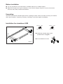
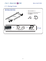
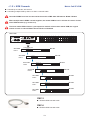
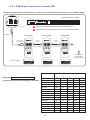
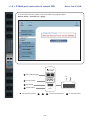
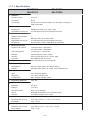
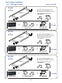
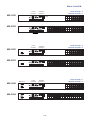
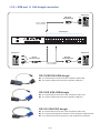
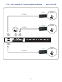
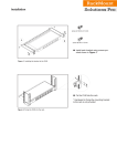
User Manual
Matrix Cat6
KVM
MU-IP1613 / 1624
MU-IP3213 / 3224
Matrix Cat6 KVM
MU-1602 / 1603 / 1604
MU-3202 / 3203 / 3204
Legal Information
First English printing, October 2002
Information in this document has been carefully checked for accuracy; however, no guarantee is given to the correctness
of the contents. The information in this document is subject to change without notice. We are not liable for any injury or
loss that results from the use of this equipment.
Safety Instructions
Please read all of these instructions carefully before you use the device. Save this manual for
future reference.
■
■
■
■
■
■
■
■
■
■
■
Unplug equipment before cleaning. Don’t use liquid or spray detergent; use a moist cloth.
Keep equipment away from excessive humidity and heat. Preferably, keep it in an air-conditioned environment with
temperatures not exceeding 40º Celsius (104º Fahrenheit).
When installing, place the equipment on a sturdy, level surface to prevent it from accidentally falling and causing dam
age to other equipment or injury to persons nearby.
When the equipment is in an open position, do not cover, block or in any way obstruct the gap between it and the
power supply. Proper air convection is necessary to keep it from overheating.
Arrange the equipment’s power cord in such a way that others won’t trip or fall over it.
If you are using a power cord that didn’t ship with the equipment, ensure that it is rated for the voltage and current
labeled on the equipment’s electrical ratings label. The voltage rating on the cord should be higher than the one listed
on the equipment’s ratings label.
Observe all precautions and warnings attached to the equipment.
If you don’t intend on using the equipment for a long time, disconnect it from the power outlet to prevent being dam
aged by transient over-voltage.
Keep all liquids away from the equipment to minimize the risk of accidental spillage. Liquid spilled on to the power
supply or on other hardware may cause damage, fire or electrical shock.
Only qualified service personnel should open the chassis. Opening it yourself could damage the equipment and invali
date its warranty.
If any part of the equipment becomes damaged or stops functioning, have it checked by qualified service personnel.
What the warranty does not cover
■
■
■
Any product, on which the serial number has been defaced, modified or removed.
Damage, deterioration or malfunction resulting from:
Accident, misuse, neglect, fire, water, lightning, or other acts of nature, unauthorized product modification, or
failure to follow instructions supplied with the product.
Repair or attempted repair by anyone not authorized by us.
Any damage of the product due to shipment.
Removal or installation of the product.
Causes external to the product, such as electric power fluctuation or failure.
Use of supplies or parts not meeting our specifications.
Normal wear and tear.
Any other causes which does not relate to a product defect.
Removal, installation, and set-up service charges.
□
□
□
□
□
□
□
□
Regulatory Notices Federal Communications Commission (FCC)
This equipment has been tested and found to comply with the limits for a Class B digital device, pursuant to Part 15 of the
FCC rules. These limits are designed to provide reasonable protection against harmful interference in a residential installation.
Any changes or modifications made to this equipment may void the user’s authority to operate this equipment. This
equipment generates, uses, and can radiate radio frequency energy and, if not installed and used in accordance with the
instructions, may cause harmful interference to radio communications.
However, there is no guarantee that interference will not occur in a particular installation. If this equipment does cause
harmful interference to radio or television reception, which can be determined by turning the equipment off and on, the
user is encouraged to try to correct the interference by one or more of the following measures:
■ Re-position or relocate the receiving antenna.
■ Increase the separation between the equipment and receiver.
■ Connect the equipment into an outlet on a circuit different from that to which the receiver is connected.
Contents
< Part 1 > Matrix Cat6
1.1
1.2
1.3
1.4
1.5
1.6
1.7
KVM
MU-IP1613
MU-IP1624
MU-IP3213
MU-IP3224
Package contents
KVM port & Cat6 dongle connection
IP, Remote & Local console connection
IP console setting
KVM Cascade
IP Multi-port connection to remote PDU
Specifications
P.1
P.2-3
P.4-5
P.6
P.7
P.8-9
P.10
< Part 2 > Matrix Cat6 KVM
2.1
2.2
2.3
2.4
2.5
MU-1602
MU-1603
MU-1604
MU-3202
MU-3203
MU-3204
Package contents
KVM port & Cat6 dongle connection
Remote & Local console connection
KVM Cascade
Specifications
P.12
P.13-14
P.15-16
P.17
P.18
< Part 3 > Usage
3.1
3.2
3.3
3.4
3.5
KVM Button
Password
KVM OSD
KVM Hotkey / Remote Console Hotkey
DC power 12V, 24V, 48V Input
P.19
P.20
P.21
P.22
P.23
Before Installation
■ It is very important to mount the KVM in a suitable cabinet or on a stable surface.
■ Make sure the place has a good ventilation, is out of direct sunlight, away from sources of excessive
dust, dirt, heat, water, moisture and vibration.
Unpacking
The KVM comes with the standard parts shown in package content. Check and make sure they are included
and in good condition. If anything is missing, or damage, contact the supplier immediately.
Installation for standalone KVM
A
B
Cy
r
be
Vie
w
Figure 1.
Screw A: 2 pcs
Screw B: 8 pcs
M3.2 x 4.5 mm
M4 x 10 mm
■
Install each bracket using screws
provided shown in Figure 1.
■
Fix the KVM into the rack
< Part 1 > Matrix Cat6
KVM
Matrix Cat6 IP KVM
< 1.1 > Package Content
MU-IP1613 / MU-IP3213
MU-IP1624 / MU-IP3224
•
Matrix IP KVM unit x 1
•
Mounting set w/ bracket & screws x 1
•
Power adapter w/ power cord
( for KVM ) x 1
KVM unit
Cy
r
be
Vie
w
+
Receiver box
for remote console
+
Receiver’s power adapter
w/ power cord
P.1
X 1 set
CE-6 KVM cable
for receiver box
Local
Console
IP console x 1
Local console x 1
Remote console x 1
Remote
Console 1
MU-IP1613
16
15
14
13
12
11
10
9
8
7
6
5
4
3
2
1
Power
1
MU-IP3213
1
2
MU-IP1624
out
32
31
30
29
28
27
26
25
16
15
14
13
12
11
10
9
24
23
22
21
20
19
18
17
8
7
6
5
4
3
2
1
in
Cascade
Local
Console
IP console x 2
Local console x 1
Remote console x 1
Remote
Console 1
16
15
14
13
12
11
10
9
8
7
6
5
4
3
2
1
Power
1
2
MU-IP3224
32
31
30
29
28
27
26
25
16
15
14
13
12
11
10
9
24
23
22
21
20
19
18
17
8
7
6
5
4
3
2
1
1
Multi
2
Multi
1
Flash
USB
Multi port for remote PDU
CyberView IP KVM provides each RJ-45 Multi port to connect up
to 16 pcs of InfraPower remote PDUs, so the users can remotely
control & manage multi servers & max. 16 pcs remote PDU
( 16 pcs remote PDU x 2 for dual Multi port )
P.2
Flash
USB
< 1.2 > KVM port & Cat6 dongle connection
Matrix Cat6 IP KVM
USB Servers
DG-100SD
DVI-USB dongle
USB
CAT 5 / 6 cable
max. 40 meters
DVI-D
Cat6 KVM port
32
31
30
29
28
27
26
25
16
15
14
13
12
11
10
9
24
23
22
21
20
19
18
17
8
7
6
5
4
3
2
1
PS/2 Servers
USB Servers
PS/2
VGA
DG-100S
VGA-USB dongle
DG-100
VGA-PS/2 dongle
CAT 5 / 6 cable
max. 40 meters
USB
VGA
DG-100SD DVI-USB dongle
■ To connect DVI-D connector to the computer’s video card
■ To connect USB connector to the computer’s USB port
DG-100S VGA-USB dongle
■ To connect DB-15 connector to the computer’s video card
■ To connect USB connector to the computer’s USB port
DG-100 VGA-PS/2 dongle
■ To connect DB-15 connector to the computer’s video card
■ To connect PS/2 keyboard connector to the computer’s keyboard port
■ To connect PS/2 mouse connector to the computer’s mouse port
P.3
< 1.3 > IP, Remote & Local console connection
Inter net
Network device
hub or router
CAT 5 / 6 cable
max. 100m
Remote
USB console
Receiver
CAT 5 / 6 cable
max. 150m
2
Local
USB
console
Remote
Cat6
Console 1
32
31
30
29
28
27
26
25
16
15
14
13
12
11
10
9
24
23
22
21
20
19
18
17
8
7
6
5
4
3
2
1
1
Inter net
Network device
hub or router
CAT 5 / 6 cable
max. 100m
P.4
How to use a receiver to connect a remote console
Receiver
Local
Computer
Matrix Cat6 IP KVM
Monitor
Remote I/O
Power
USB
K/B
Local
Mouse
Remote
Button
to
PC
Button
to
KVM switch
The receiver provides a hotkey function for remote console. Please refer to P.22
32
31
30
29
28
27
26
25
16
15
14
13
12
11
10
9
24
23
22
21
20
19
18
17
8
7
6
5
4
3
2
1
Monitor
Remote
Console
Local computer
( Optional setup )
CE-6
Combo
KVM cable
VGA
cable
Cat6 cable
up to 150m
12V DC Power
Adapter
P.5
< 1.4 > IP console setting
After the cable connection, please take the following steps to configure the IP KVM :
1. Download IPKVMsetup.exe from the link:
http://rackmount-solutions-pro.comp/utilities/ipkvmsetup.exe
2. Double click IPKVMsetup.exe to configure the IP KVM by device setup as below.
3. Click Refresh Device to search the connected IP KVM
4. Select the M.A.C. address, which you want to setup, then click Query Device
5. Enter Super user login. The default is super
6. Enter Super user password. The default is pass
7. Enter the new super user password
8. Re-enter the new password
9. Change the desired IP address / Subnet mask / Gateway, then click Setup Device to confirm the setting to IP KVM
10. The default address is as below:-■ The single IP KVM model, such as MU-IP3213 - http://192.168.1.22
■
The dual IP KVM model,
such as MU-IP3224 - http://192.168.1.22 (for 1st IP)
http://192.168.1.23 (for 2nd IP)
11. Open Internet Explorer ( I.E. ), version 6.0 or above
12. Enter the IP KVM address into the address bar
- For Single IP - http://192.168.1.22
- For Dual IP - http://192.168.1.22 ( for 1st IP )
http://192.168.1.23 ( for 2nd IP )
13. Enter username ( default is super )
Password ( default is pass )
14. After successful login to IP KVM, the user will enter the main page of IP KVM
P.6
< 1.5 > KVM Cascade
■
■
Matrix Cat6 IP KVM
Cascade up to 8 levels, 256 servers
Cascading multiple KVM by CMC-6 or CMC-3 cascade cable.
Cascaded KVMs from level 2 to 8 must be the models of MU-1602 / MU-3202 or M-802 / M-1602.
When multiple matrix KVMs cascade together, the master KVM at level 1 will take all control of other
slave KVM switches (e.g. level 2 to 8).
The slave matrix KVM will be as a port expansion module of the master matrix KVM, the original
remote console on slave KVM will be sacrificed and disabled.
Master KVM
Power
out
32
31
30
29
28
27
26
25
16
15
14
13
12
11
10
9
24
23
22
21
20
19
18
17
8
7
6
5
4
3
2
1
in
Cascade
To cascade IN port
Slave KVM
level 2
16
15
14
13
12
11
10
9
8
7
6
5
4
3
2
1
Slave KVM
level 3
Slave KVM
level 4
MU-1602
16
15
14
13
12
11
10
9
8
7
6
5
4
3
2
1
MU-1602
16
15
14
13
12
11
10
9
8
7
6
5
4
3
2
1
Slave KVM
level 5
Slave KVM
level 6
Slave KVM
level 7
Slave KVM
level 8
MU-1602
16
15
14
13
12
11
10
9
8
7
6
5
4
3
2
1
32
31
30
29
28
27
26
25
16
15
14
13
12
11
10
9
24
23
22
21
20
19
18
17
8
7
6
5
4
3
2
1
32
31
30
29
28
27
26
25
16
15
14
13
12
11
10
9
24
23
22
21
20
19
18
17
8
7
6
5
4
3
2
1
32
31
30
29
28
27
26
25
16
15
14
13
12
11
10
9
24
23
22
21
20
19
18
17
8
7
6
5
4
3
2
1
CMC-3
■ 3ft Matrix KVM cascade cable
CMC-6
■ 6ft Matrix KVM cascade cable
P.7
MU-1602
MU-3202
MU-3202
MU-3202
< 1.6 > IP Multi-port connection to remote PDU
CyberView IP KVM provides RJ-45 Multi port for the user to remotely control and manage servers & PDU together.
CyberView Matrix IP KVM
32
31
30
29
28
27
26
25
16
15
14
13
12
11
10
9
24
23
22
21
20
19
18
17
8
7
6
5
4
3
2
1
Other band IP KVM can NOT connect InfraPower PDU
Each RJ-45 Multi port connect max. 16 pcs of InfraPower PDU
To Multi port
1st level PDU
To LINK port
of the 1st PDU
LINK
2nd level PDU
CAT. 5 / 6
cable
OUT
LINK
Up to 20 meters
CURRENT (A)
ON
1
2
3
4
5
6
7
LINK
Up to 20 meters
ON
8
1
2
3
4
5
6
7
225
DIP
ON
8
1
DIP
2
RESET
DIP
ON
OUT
CURRENT (A)
225
DIP
RESET
ON
CAT. 5 / 6
cable
OUT
CURRENT (A)
225
3rd level PDU
3
4
5
6
7
8
To LINK port
of next PDU
( Up to 16 levels )
RESET
DIP
ON
DIP
Dip switch setting
1 2 3 4 5 6 7 8
1 2 3 4 5 6 7 8
1 2 3 4 5 6 7 8
Cascaded PDUs
Using the
dip switch no. 1, 2, 3, 4 & 8
to setup each PDU level acording to the table :
Dip switch no.
1
2
3
4
8
1st PDU
On
On
On
On
Off
2nd PDU
Off
On
On
On
Off
3rd PDU
On
Off
On
On
Off
4th PDU
Off
Off
On
On
Off
5th PDU
On
On
Off
On
Off
6th PDU
Off
On
Off
On
Off
7th PDU
On
Off
Off
On
Off
8th PDU
Off
Off
Off
On
Off
9th PDU
On
On
On
Off
Off
10th PDU
Off
On
On
Off
Off
11th PDU
On
Off
On
Off
Off
12th PDU
Off
Off
On
Off
Off
13th PDU
On
On
Off
Off
Off
14th PDU
Off
On
Off
Off
Off
15th PDU
On
Off
Off
Off
Off
16th PDU
Off
Off
Off
Off
Off
P.8
< 1.6 > IP Multi-port connection to remote PDU
Matrix Cat6 IP KVM
To access the PDU GUI, please enter the IP KVM main page and select
Remote Power > Start Service > Apply
LINK
1
OUT
PDU cascade port
ON
CURRENT (A)
2
225
Current display
ON
■
3
Dip switch
4
Reset button
For rackmount PDU,
1
OFF
ON
DIP
DIP
2
3
4
5
6
7
8
1
2
3
4
5
6
7
8
RESET
2
3
4
P.9
on the front panel left ,
1
on the rear panel
< 1.7 > Specifications
MU-IP1613
MU-IP3213
▀
▀
▀
▀
MU-IP1624
MU-IP3224
KVM Port
Number of ports:
16 or 32
Connector:
RJ-45
Connectivity:
DVI-D / VGA connector dongle up to 40 meters (132 feet) via
Cat6 / Cat5 cable
Local Console
Monitor port:
HDDB15-pin VGA, up to 1600 x 1200
Keyboard & mouse port:
2 x USB type connector for keyboard & mouse
Cat6 Remote Console
Number of remote port:
1
Monitor port:
DB15-pin VGA, up to 1600 x 1200
Keyboard & mouse port:
2 x USB type connector for keyboard & mouse
Remote I/O:
RJ45 via Cat5 / Cat5e / Cat6 cable up to 500 feet
IP Remote Console
Number of IP console:
1 for MU-IP1613 / MU-IP3213
2 for MU-IP1624 / MU-IP3224
User management:
15-user login, 1 x active user
Browser:
Internet Explorer, Firefox, Safari
Security:
SSL v3, RSA, AES, HTTP / HTTPs, CSR
IP Access:
RJ45 Ethernet per IP console
▀
Expansion:
Up to 256 servers by 8-level cascade
▀
Compatibility
▀
Multi-platform:
Mix PCs, SUNs, IBMs, HPs, DELLs Server
Support:
Windows Vista / 2003 / XP / 2000, Linux, Netware, Unix
Power
Input:
AC / DC power adapter
Option DC:
12V / 24V / 48V DC input
Consumption:
Max. 48 Watt, Standby 5 Watt
▀
Regulatory Approval:
FCC, CE
▀
Environmental
▀
▀
Operating:
0 to 50°C
Storage:
-5 to 60°C
Relative humidity:
90%, non-condensing
Shock:
50G peak acceleration (11ms, half-sine wave)
Vibration:
58~100Hz / 0.98G (11ms / cycle)
Product Information
Dimension (W x D x H):
448 x 180 x 44 mm / 17.6 x 7.1 x 1.73 inch
Net weight:
3 kg / 6.5 lb
Packing Information
Dimension (W x D x H):
510 x 400 x 77 mm / 20.1 x 15.7 x 3 inch
Gross weight:
5 kg / 11 lb
P.10
P.11
Part 2. Matrix Cat6 KVM
< 2.1 > Package Content
Matrix Cat6 KVM
MU-1602
or
MU-3202
KVM unit
Cy
r
be
Vie
•
MU-1602 or MU-3202 KVM unit x 1
•
Mounting set w/ bracket & screws x 1
•
Power adapter w/ power cord
( for KVM ) x 1
w
+
+
Receiver box
for remote console
Receiver’s power adapter
w/ power cord
MU-1603
or
MU-3203
KVM unit
Cy
r
be
Vie
CE-6 KVM cable
for receiver box
•
MU-1603 or MU-3203 KVM unit x 1
•
Mounting set w/ bracket & screws x 1
•
Power adapter w/ power cord
( for KVM ) x 1
w
+
+
Receiver box
for remote console
Receiver’s power adapter
w/ power cord
MU-1604
or
MU-3204
KVM unit
Cy
r
be
Vie
X 2 sets
CE-6 KVM cable
for receiver box
•
MU-1604 or MU-3204 KVM unit x 1
•
Mounting set w/ bracket & screws x 1
•
Power adapter w/ power cord
( for KVM ) x 1
w
+
Receiver box
for remote console
X 1 set
+
Receiver’s power adapter
w/ power cord
P.12
X 3 sets
CE-6 KVM cable
for receiver box
Matrix Cat6 KVM
Local
Console
Local console x 1
Remote console x 1
Remote
Console 1
MU-1602
16
15
14
13
12
11
10
9
8
7
6
5
4
3
2
1
Power
MU-3202
out
32
31
30
29
28
27
26
25
16
15
14
13
12
11
10
9
24
23
22
21
20
19
18
17
8
7
6
5
4
3
2
1
in
Cascade
Local
Console
MU-1603
Local console x 1
Remote console x 2
Remote
Console 1
16
15
14
13
12
11
10
9
8
7
6
5
4
3
2
1
Remote-2
MU-3203
MU-1604
Remote-3
Local
Console
32
31
30
29
28
27
26
25
16
15
14
13
12
11
10
9
24
23
22
21
20
19
18
17
8
7
6
5
4
3
2
1
Local console x 1
Remote console x 3
Remote
Console 1
16
15
14
13
12
11
10
9
8
7
6
5
4
3
2
1
Remote-2
MU-3204
P.13
32
31
30
29
28
27
26
25
16
15
14
13
12
11
10
9
24
23
22
21
20
19
18
17
8
7
6
5
4
3
2
1
< 2.2 > KVM port & Cat6 dongle connection
USB Servers
DG-100SD
DVI-USB dongle
USB
CAT 5 / 6 cable
max. 40 meters
DVI-D
Cat6 KVM port
32
31
30
29
28
27
26
25
16
15
14
13
12
11
10
9
24
23
22
21
20
19
18
17
8
7
6
5
4
3
2
1
PS/2 Servers
USB Servers
PS/2
VGA
DG-100S
VGA-USB dongle
DG-100
VGA-PS/2 dongle
CAT 5 / 6 cable
max. 40 meters
USB
VGA
DG-100SD DVI-USB dongle
■ To connect DVI-D connector to the computer’s video card
■ To connect USB connector to the computer’s USB port
DG-100S VGA-USB dongle
■ To connect DB-15 connector to the computer’s video card
■ To connect USB connector to the computer’s USB port
DG-100 VGA-PS/2 dongle
■ To connect DB-15 connector to the computer’s video card
■ To connect PS/2 keyboard connector to the computer’s keyboard port
■ To connect PS/2 mouse connector to the computer’s mouse port
P.14
< 2.3 > Local console & remote console connection
Matrix Cat6 KVM
Receiver
Remote
USB console 3
Receiver
Remote
USB console 1
CAT 5 / 6 cable
max. 150m
CAT 5 / 6 cable
max. 150m
Remote
Cat6
Console 3
Local
USB
console
Remote
Cat6
Console 1
32
31
30
29
28
27
26
25
16
15
14
13
12
11
10
9
24
23
22
21
20
19
18
17
8
7
6
5
4
3
2
1
Remote
Cat6
Console 2
Receiver
CAT 5 / 6 cable
max. 150m
P.15
Remote
USB console 2
How to use a receiver to connect a remote console
Receiver
Local
Computer
Monitor
Remote I/O
Power
USB
K/B
Mouse
Local
Remote
Button
to
PC
Button
to
KVM switch
The receiver provides a hotkey function for remote console. Please refer to P.22
32
31
30
29
28
27
26
25
16
15
14
13
12
11
10
9
24
23
22
21
20
19
18
17
8
7
6
5
4
3
2
1
Monitor
Remote
Console
Local computer
( Optional setup )
CE-6
Combo
KVM cable
VGA
cable
Cat6 cable
up to 150m
12V DC Power
Adapter
P.16
< 2.4 > KVM Cascade
■
■
Matrix Cat6 KVM
Cascade up to 8 levels, 256 servers
Cascading multiple KVM by CMC-6 or CMC-3 cascade cable.
Cascaded KVMs from level 2 to 8 must be the models of MU-1602 / MU-3202 or M-802 / M-1602.
When multiple matrix KVMs cascade together, the master KVM at level 1 will take all control of other
slave KVM switches (e.g. level 2 to 8).
The slave matrix KVM will be as a port expansion module of the master matrix KVM, the original
remote console on slave KVM will be sacrificed and disabled.
Master KVM
Power
out
32
31
30
29
28
27
26
25
16
15
14
13
12
11
10
9
24
23
22
21
20
19
18
17
8
7
6
5
4
3
2
1
in
Cascade
To cascade IN port
Slave KVM
level 2
16
15
14
13
12
11
10
9
8
7
6
5
4
3
2
1
Slave KVM
level 3
Slave KVM
level 4
MU-1602
16
15
14
13
12
11
10
9
8
7
6
5
4
3
2
1
MU-1602
16
15
14
13
12
11
10
9
8
7
6
5
4
3
2
1
Slave KVM
level 5
Slave KVM
level 6
Slave KVM
level 7
Slave KVM
level 8
MU-1602
16
15
14
13
12
11
10
9
8
7
6
5
4
3
2
1
32
31
30
29
28
27
26
25
16
15
14
13
12
11
10
9
24
23
22
21
20
19
18
17
8
7
6
5
4
3
2
1
32
31
30
29
28
27
26
25
16
15
14
13
12
11
10
9
24
23
22
21
20
19
18
17
8
7
6
5
4
3
2
1
32
31
30
29
28
27
26
25
16
15
14
13
12
11
10
9
24
23
22
21
20
19
18
17
8
7
6
5
4
3
2
1
CMC-3
■ 3ft Matrix KVM cascade cable
CMC-6
■ 6ft Matrix KVM cascade cable
P.17
MU-1602
MU-3202
MU-3202
MU-3202
< 2.5 > Specifications
MU-1602
MU-3202
▀
▀
▀
MU-1603
MU-3203
MU-1604
MU-3204
KVM Port
Number of ports:
16 or 32
Connector:
RJ-45
Connectivity:
DVI-D / VGA connector dongle up to 40 meters (132 feet) via
Cat6 / Cat5 cable
Local Console
Monitor port:
1 x DB15-pin VGA, up to 1600 x 1200
Keyboard & mouse port:
2 x USB type connector for keyboard & mouse
Cat6 Remote Console
Number of remote port:
1 for MU-1602 / MU-3202
2 for MU-1603 / MU-3203
3 for MU-1604 / MU-3204
Monitor port:
DB15-pin VGA, up to 1600 x 1200
Keyboard & mouse port:
2 x USB type connector for keyboard & mouse
Remote I/O:
RJ45 via Cat5 / Cat5e / Cat6 cable up to 500 feet
▀
Expansion:
Up to 128 servers by 8-level cascade
▀
Compatibility
▀
Multi-platform:
Mix PCs, SUNs, IBMs, HPs, DELLs Server
Support:
Windows Vista / 2003 / XP / 2000, Linux, Netware, Unix
Power
Input:
AC / DC power adapter
Option DC:
12V / 24V / 48V DC input
Consumption:
Max. 48 Watt, Standby 5 Watt
▀
Regulatory Approval:
FCC, CE
▀
Environmental
▀
▀
Operating:
0 to 50°C
Storage:
-5 to 60°C
Relative humidity:
90%, non-condensing
Shock:
50G peak acceleration (11ms, half-sine wave)
Vibration:
58~100Hz / 0.98G (11ms / cycle)
Product Information
Dimension (W x D x H):
448 x 180 x 44 mm / 17.6 x 7.1 x 1.73 inch
Net weight:
3 kg / 6.5 lb
Packing Information
Dimension (W x D x H):
510 x 400 x 77 mm / 20.1 x 15.7 x 3 inch
Gross weight:
5 kg / 11 lb
P.18
Part 3. Usage
Matrix KVM Usage
3.1 KVM Button
Power ON
■ Turn off all servers and KVM switches
■ Make sure all cables / connectors are properly connected
■ Recommend Power ON sequence is monitor, KVM switch finally computer
Front Panel - Port LED Indications
16 ports
Bank no.
PC port LEDs
Channel
button
Bank
button
32 ports
Bank no.
7-Segment BANK LED indication
PC port LEDs
Online : Blue LED on indicating a PC is connecting to the port
Active : Green LED on indicating a selected channel
Remote : Orange LED on indicating the port is selecting by IP / remote console
Channel button
Press to select channel from 01 to 32
Bank button
Select the bank from 1 to 8
P.19
3.2 Password
The password is enabled by default, the default password is “00000000” eight zeros (Do not use “0” on
number pad)
■ Enable password
1. Press the KVM hotkey Scroll Lock + Scroll Lock + U
2. Logout the KVM by pressing the hotkey Scroll Lock + Scroll Lock + P
3. In SUPERVISOR level, enter “00000000” eight zeros in user name & password field
(Do not use “0” on number pad)
4. In USER level, press Space bar + Enter in user name & password field
Remark: Automatic logout after 10 minutes of inactivity
■
Set your own user name & password
1. Login the KVM in SUPERVISOR level by pressing “00000000” eight zeros in user name & password
field
2. Call KVM OSD menu by pressing the KVM hotkey Scroll Lock + Scroll Lock + Space Bar
3. Press F1 to the MAIN MENU
4. Select “USER SECURITY”
5. Set password in SUPERVISOR & USER level
a. In the left-top row “S” (SUPERVISOR), press Enter to set your own user name & password
b. In the row 1 to 8 (USER), press Enter to set your own user name & password
6. Press Enter to save the setting or press Esc to cancel the editing without any change
Remark: a. Blank has underscore, while SPACE doesn’t have
b. Press any alphanumeric key to move to next input item. SPACE is treated as a valid
character
■
Change your password
1. Login the KVM in SUPERVISOR level by pressing your own user name & password
2. Call KVM OSD menu by pressing the KVM hotkey Scroll Lock + Scroll Lock + Space Bar
3. Press F1 to the MAIN MENU
4. Select “USER SECURITY”
5. Change password in SUPERVISOR & USER level
a. In the left-top row “S” (SUPERVISOR), press Enter to change your user name & password
b. In the row 1 to 8 (USER), press Enter to change your user name & password
6. Press Enter to save the setting or press Esc to cancel the editing without any change
Remark: a. Blank has underscore, while SPACE doesn’t have
b. Press any alphanumeric key to move to next input item. SPACE is treated as a valid
character
■
■
Disable your password
1. Press the KVM hotkey Scroll Lock + Scroll Lock + U
2. Logout the KVM by pressing the KVM hotkey Scroll Lock + Scroll
3. You don’t need user name & password to access the KVM OSD menu
Forget your password
Please contact your supplier for further support
Remark:
You must press the KVM hotkey within 2 seconds
A beep sound will be heard for successful entering KVM hotkey
■
■
P.20
Lock + P
3.3 KVM OSD
Matrix KVM Usage
OSD Menu
OSD operation
next to the system name
The PC is powered on
next to the system name
The PC is selected
F1
Access F1 MAIN MENU
F2
Logout the OSD menu
F3
Previous menu
Esc
Cancel / Quit
Enter
Complete / Switch to selected port
Switch to previous or next port
PgUp/PgDn
Switch to previous bank or next bank
1/2/3/4
Display port 01 ~ 08 / 09 ~ 16 / 17 ~ 24 / 25 ~ 32
Remark: Display port 17 ~ 32 for 32 port model only
F1 Main Menu
01 LANGUAGE
OSD language change
02 PORT NAME EDIT
Define port name
03 PORT SEARCH
Quick searching by port name
04 USER SECURITY
Change password
05 ACCESS LIST
Define user access authority
06 HOTKEY
Change hotkey
07 TIME SETTINGS
Modify scan display time interval
08 OSD MOUSE
Modify OSD mouse speed
P.21
3.4 KVM Hotkey & Remote Console Hotkey
Matrix KVM Usage
Local Console Hotkey
Function
Scroll Lock + Scroll Lock + Space Bar
Calling OSD menu
Right-button mouse + Esc
Calling OSD menu
Scroll Lock + Scroll Lock +
Switch to previous port
Scroll Lock + Scroll Lock +
Switch to next port
Scroll Lock + Scroll Lock +
PgUp / PgDn
Switch to previous bank or next bank
Scroll Lock + Scroll Lock +
Bank no. + Port no.
Switch to specific port
Scroll Lock + Scroll Lock +
B
Turn the buzzer ON and OFF
* Default the buzzer is ON
Scroll Lock + Scroll Lock +
P
Logout the KVM if password security is
ON. Show up the status windows
Advance hotkeys (for Supervisor login only)
Scroll Lock + Scroll Lock +
S
Activate auto-scan mode for connected
servers
*Press any key to exit the auto-scan
mode
Scroll Lock + Scroll Lock +
R
Reset all the KVM settings to factory
default
*Except User Security settings
Scroll Lock + Scroll Lock +
U
Disable and enable password security
*Default security is ON
Scroll Lock + Scroll Lock +
L
To enable / disable the screen saving
function and 10 minutes auto-logout
*Default the screen saving is OFF
Remarks:
■
■
■
■
Example of “Scroll Lock + Scroll Lock + Bank no. + Port no.”
- Bank No. : 1 to 8
- Port No. : 01 to 16
- e.g. Bank 1 Port 4 : Scroll Lock + Scroll Lock + 1 + 0 + 4
- e.g. Bank 2 Port 16 : Scroll Lock + Scroll Lock + 2 + 1 + 6
You must press the hotkey within 2 seconds
A beep sound will be heard for successful entering
The numeric keypad is not supported, while in OSD screen, the arrow keys, PgUp,
PgDn, and Enter keys are supports
Remote Console Hotkey
Function
Scroll Lock + Scroll Lock +
C
Toggle switch between remote & local port
Scroll Lock + Scroll Lock +
Q
Turn the buzzer ON & OFF
*Default the buzzer is ON
Scroll Lock + Scroll Lock +
S
Activate auto-scan mode for remote & local port
*The scan time interval is 5 seconds
Scroll Lock + Scroll Lock +
A
Auto-adjust the video signal
P.22
3.5 DC Power 12V, 24V, 48V Input
Model
Matrix KVM Usage
12V
24V
48V
Input voltage:
12-Volt
24-Volt
48-Volt
Input range:
9 ~ 18V
18 ~ 36V
36 ~ 75V
- No load
50 mA
50 mA
50 mA
- Full load
4950 mA
2450 mA
1220 mA
Output voltage:
12-Volt
12-Volt
12-Volt
Output current:
4.16A
4.16A
4.16A
Efficiency
84%
85%
85%
Input rating
Input current
Output rating
Remarks:
Package does not include power cord
■
P.23
The company reserves the right to modify product specifications without prior notice and assumes no responsibility
for any error which may appear in this publication.
All brand names, logo and registered trademarks are properties of their respective owners.
Copyright 2011 Rackmount-Solutions-Pro.com. All rights reserved.