1
SF_/A/ S
[RaFTZ
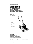
MODEL NUMBER 917.378290
• Assembly
• Operation
• Customer
•Responsibilities
• Service
• Adjustments
• Repair Parts
Caution:
Read and Follow
all Safety Rules
and Instructions
Before Operating
This Equipment
OWNER'S MANUAL
SAFETY RULES
PL.
TO
P.E,,E.T
ACCIDE.TAL
START,.G
W.EN UP.
TRANSPORT,.
AD USTI.G
OR
,
CAUT,ON:
A'WAYSO,SCON.ECTSPARKPLOGWIREANDP.ACEW,
REW.EREITCANNOTCONTACTSPA
REPAIRS.
IMPORTANT
SAFETY STANDARDS REQUIRE OPERATOR PRESENCE CONTROLS TO MINIMIZE THE RiSK OF INJURY. YOUR UNIT iS EQUIPPED WITH
SUCH CONTROLS.
DO NOT ATTEMPT TO DEFEAT THE FUNCTION OF THE OPERATOR PRESENCE CONTROLS UNDER ANY CIRCUMSTANCES.
TRAINING:
•
Read this operator's manual carefully. Become familiar with
the controls and know how to operate your mower properly.
Learn how to quickly stop mower.
•
Always stop the engine whenever you leave or are not using
your mower, or before crossing driveways, walks, roads, and
any gravel-covered areas.
•
Do not allow children to use your mower. Never ailow adults
to use mower without proper instructions.
•
Never direct discharge of material toward bystanders nor
allow anyone near the mower while you are operating it.
•
Keep the area of operation clear of all persons, especially
small children and pets.
•
•
Use mower only as the manufacturer intended and as described in this manual.
Before cleaning, inspecting, or repairing your mower, stop
the engine and make absolutely sure the blade and alt
moving parts have stopped. Then disconnectthe spark plug
wire and keep it away from the spark plug to prevent
accidental starting.
•
Do not continue to run your mower if you hit a foreign object.
Follow the procedure outlined above, then repair any damage before restarting and operating you mower.
•
Do not change the governor settings or overspeed the
engine. Engine damage or personal injury may result.
•
Do not operate your mower if it vibrates abnormally. Excessive vibration is an indication of damage; stop the engine,
safely checkfor the cause of vibration and repair as required.
Do not operate mower if it has been dropped or damaged in
any manner. Always have damage repaired before using
your mower.
Do notuse accessory attachments that are notrecommended
by the manufacturer. Use of such attachments may be
hazardous.
Be aware that the mower blade turns when the engine is
running.
Do not run the engine indoors. Exhaust fumes are dangerous.
PREPARATION:
•
Always thoroughly check the area to be mowed and clear itof
all stones, sticks, wires, bones, and other foreign objects.
These objects will be thrown by the blade and can cause
severe injury.
•
Always wear safety glasses or eye shieldswhen starting and
while using your mower.
•
Dress properly. Do not operate mower when barefoot or
wearing open sandals. Wear only solid shoes with good
traction when mowing.
•
•
•
Never cut grass by pulling the mower towards you. Mow
across the face of slopes, never up and down or you might
lose your footing. Do not mow excessively steep slopes.
Use caution when operating the mower on uneven terrain or
when changing directions - maintain good footing.
Never operate your mower without proper guards, plates,
grass catcher or other safety devices in place.
MAINTENANCE AND STORAGE:
Check fuel tank before starting engine. Do not fill gas tank
indoors, when the engine isrunning orwhen the engine is hot.
Allow the engine to coolfor several minutes before filling the
gas tank. Clean off any spilled gasoline before startingthe
engine.
•
Check the blade and the engine mounting bolts often to be
sure they are tightened properly.
•
Always make whee! height adjustments before starting your
mower. Never attempt to do this while the engine is running.
Check all bolts, nuts and screws at frequent intervals for
proper tightness to be sure mower is in safe working condition.
•
Keep all safety devices in place and working.
Mow only in daylight or good artificial light.
•
To reduce fire hazard, keep the engine free of grass, leaves
or excessive grease and oil.
•
Check grass catcher often for deterioration and wear and
replace worn bags. Use only replacement bags that are
recommended by and comply with specifications of the
manufacturer of your mower.
•
Always keep a sharp blade on your mower.
•
Allow engine to cool before storing in any enclosure.
•
Never store mower with fuel in the tank inside a building
where fumes may reach an open flame or an ignitionsource
suchas a hot water heater, space heater, ctothesdryer, etc.
OPERATION:
•
Keep your eyes and mind on your mower and the area being
cut. Do not let other interests distract you.
•
Do not mow wet or slippery grass. Never run while operating
you r mower. Always be sure of your footing - keep a firm hold
on the handles and walk.
Do not put hands or feet near or under rotating parts. Keep
clear of the discharge opening at all times.
i ]1i|
IT
MEANS
ATTENTIONtII
LOOK
FOR - THIS
SYMBOL
i
m
i|
BECOME
YOUR SAFETY
INVOLVED.
TO
POINT ALERT!!?
OUT IMPORTANT
SAFETY IS PRECAUTIONS.
2
i
.
I
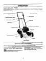
PRODUCT
CONGRATULATIONS on your purchase-of a Sears Lawn
Mower. It has been designed, engineered and manufactured to give you the best possible dependability and
performance.
SPECIFICATIONS
HORSEPOWER:
3.8
DISPLACEMENT:
9.0 CU. IN.
Should you experience any problem you cannot easily
remedy, please contact your nearest Sears Authorized
Service Center/Department.
We have competent, welltrained technicians and the proper tools to service or repair
this lawn mower.
GASOLINECAPACITY
AND TYPE:
1.5QUARTS
UNLEADED REGULAR
OIL TYPE (API-SG):
SAE 80 (ABOVE 32°F)
SAE 5W-30 (BELOW32°F)
Please read and retain this manual. The instructions will
enable you to assemble and maintain your lawn mower
properly. Always observe the "SAFETY RULES".
OIL CAPACITY:
20 OZS.
SPARK PLUG:
(GAP: .030")
CHAMPION RJ19-LM
STD361458
VALVE CLEARANCE:
INTAKE: .008
EXHAUST: .008
SERIAL
NUMBER
SOLID STATE IGNITION
AIR GAP:
.0125 IN.
DATE OF PURC HASE
BLADE BOLTTORQUE:
35-40 FT. LBS.
MODEL
NUMBER
917.378290
THE MODEL AND SERIAL NUMBERS WILL BE FOUND
ON A DECAL ATTACHED TO THE REAR OF THE
LAWN MOWER HOUSING
YOU SHOULD RECORD BOTH SERIAL N UMBER AND
DATE OF PURCHASE AND KEEP IN A SAFE PLACE
FOR FUTURE REFERENCE.
MAINTENANCE
AGREEMENT
A Sears Maintenance Agreement is available on this product. Contact your nearest Sears store for details.
CUSTOMER
RESPONSIBILITIES
•
Read and observe the safety rules.
°
•
Follow a regular schedule in maintaining, caring for and using your lawn mower.
Follow the instructions under "Customer Responsibilities" and "Storage" sections of this owner's manual.
LIMITED
ONE YEAR WARRANTY
ON CRAFTSMAN
POWER
MOWER
For one year from date of purchase, when this Craftsman Lawn Mower is maintained, lubricated, and tuned up
according to the operating and maintenance instructions in the owner's manual, Sears will repair free of charge any
defect in material or workmanship.
If this Craftsman Lawn Mower is used for commercial or rental purposes, this warranty applies for only 90 days from
the date of purchase.
This Warranty does not cover:
° Expendable items which become worn during normal use, such as rotary mower blades, blade adapters, belts,
air cleaners and spark plug.
•
Repairs necessary because of operator abuse or negligence, including bent crankshafts and the failure to maintain
the equipment according to the instructions contained in the owner's manual.
WARRANTY SERVICE IS AVAILABLE BY RETURNING THE CRAFTSMAN POWER MOWER TO THE NEAREST
SEARS SERVICE CENTER/DEPARTMENT IN THE UNITED STATES. THIS WARRANTY APPLIES ONLY WHILE
THIS PRODUCT IS IN USE IN THE UNITED STATES.
This Warranty gives you specific legal rights, and you may also have other rights which vary from state to state.
SEARS, ROEBUCK AND CO., D1817 WA, HOFFMAN ESTATES, ILLINOIS 60179
3
TABLE OF CONTENTS
SAFETY RULES ............................................................ 2
PRODUCT SPECIFICATIONS ....................................... 3
CUSTOMER RESPONSIBILITIES ....................... 3, 9-11
WARRANTY ................................................................... 3
ASSEMBLY .................................................................... 5
OPERATION .................................................................. 6
MAINTENANCE SCHEDULE ........................................ 9
SERVICE AND ADJ USTMENTS ................................. 12
STORAGE .................................................................... 14
TROUBLESHOOTING ................................................. 23
REPAIR PARTS - LAWN MOWER ........................ 15-19
REPAIR PARTS - ENGINE .................................... 20-22
PARTS ORDERING/SERVICE ................ BACK COVER
INDEX
A
Accessories ..................................... 5
Adjustments:
Carburetor .............................. 13
Drive Belt ................................ 12
Engine Speed ......................... 13
Handle Height ......................... 13
Height of Cut ............................. 7
Air Filter:
Replacement .......................... 11
Service .................................... 11
Assembly......................................... 5
B
Blade:
Sharpening ............................. 10
Replacement .......................... 10
C
Controls:
Drive Control ............................. 6
Engine Zone Control ................. 6
Engine Speed Control .............. 6
Operator Presence
Control Bar ............................... 6
Customer Responsibilities ..... 3, 9-11
Air Filter .................................. 11
Blade Care!Replacement ....... 10
Drive Wheels .......................... 10
Engine .................................... 11
Lubrication................................ 9
Spark Plug .............................. 11
Cutting Levels ................................. 7
E
Engine:
Air Filter .................................. 11
Oil Change .............................. 11
Oil Level .................................. 11
Oil Type .................................. 11
Starting ..................................... 8
Stopping ................................... 8
Storage ................................... 14
F
Fuel:
Capacity .................................... 3
Storage .................... {.............. 14
Type .......................................... 8
H
Handle Adjustment:
Assembly .................................. 5
Cutting Height ......................... 13
L
Lubrication:
Engine .................................... 11
Lawn Mower ............................. 9
M
Maintenance Agreement ................. 3
Maintenance Schedule ................... 9
Mowing Tips .................................... 8
0
Oil:
Engine .................................... 11
Storage ................................... 14
Operation:
Drive Control .............................
Engine Control ..........................
Grass Catcher ..........................
Mower .......................................
Operator Presence
Control Bar ...............................
7
7
7
7
7
Options:
Accessories .............................. 5
R
Repair Parts:
Engine ............................... 20-22
Lawn Mower ...................... 15-19
Responsibilities, Customer .... 3, 9-11
S
Safety Rules .................................... 2
Service and Adjustments ..............
Carburetor ..............................
Drive Belt ................................
Engine Speed .........................
Handle ....................................
12
13
12
13
13
Spark Plug ..................................... 11
Specifications .................................. 3
Speed Control:
Engine ...................................... 7
Starting the Engine .......................... 8
Stopping the Engine ........................ 8
Storage .......................................... 14
T
Trouble Shooting Chart ................. 23
W
Warranty ......................................... 3
4
i
ii
LAWN MOWER ACCESSORIES
i ii
i
These accessories were available when this lawn mower was produced. They are also available at most Sears retail outlets
and service centers. Most Sears stores can also order repair parts for you, when you provide the model number of your lawn
mower. Some of these accessories may not apply to your lawn mower.
ENGINE
SPARK PLUG
illl
MUFFLER
GAS CAN
AIR FILTER
ENGINE OIL
LAWN MOWER PERFORMANCE
STABILIZER
MULCHER KIT
LAWN MOWER MAINTENANCE
i
BLADE
BELT
ii
iiiii
LAWN MOWER
COVER
WHEELS
BLADE
ADAPTER
[r r rrr
[|
ii
i
i
ASSEMBLY
..,.
i| w i i
Read these instructions and this manual in its entirety
before you attempt to assemble or operate your new lawn
mower. Your new lawn mower has been assembled at the
factory with the exception of those parts left unassembled
for shipping purposes. All parts such as nuts, washers,
bolts, etc., necessary to complete the assembly have been
placed in the parts bag. To ensure safe and proper
operation of your lawn mower, all parts and hardware you
assemble must be tightened securely. Use the correct
tools as necessary to ensure proper tightness.
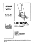
OPERATOR PRESENCE
CONTROL BAR
UPPER HANDLE
LIFT UP
TO REMOVE LAWN MOWER FROM
CARTON
•
•
•
•
Remove loose parts included with mower.
Cut down two end corners ot carton and lay end panel
down flat.
Remove all packing materials except padding between upper and lower handle and padding holding
operator presence con[rol bar to upper nan_lle.
Roll lawn mower out of carton and check carton
thoroughly for additional loose parts.
HOW TO SET UP YOUR LAWN
MOWER
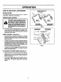
TO UNFOLD HANDLE (See Fig, 1)
IMPORTANT: UNFOLD HANDLE CAREFULLY SO AS
NOT TO PINCH OR DAMAGE CONTROL CABLES.
MOWING POSITION
LOWER HANDLE
FIG, 1
•
•
•
•
Raise handles until lower handle section locks into
place in mowing _position.
Raise upper handle section into place on lower handle,
remove protective padding and tighten both handle
knobs.
Remove handle padding holding operator presence
control bar to upper handle.
Your lawn mower handle can be adjusted for your
mowing comfort. Refer to "Adjust Handle" !n the
Service and Adjustment section of this manua!.
OPERATION
i
ill
Hi
i i.
i|
i
i
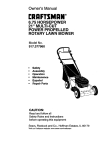
KNOW YOUR LAWN MOWER
READ THiS OWNER'S MANUAL AND SAFETY RULES BEFORE OPERATING YOUR LAWN MOWER. Compare the
illustrationswith your lawn mower to familiarize yourself with the location of various controls and adjustments. Save this
manual for future reference.
OPERATOR PRESENCE CONTROL BAR
DRIVE CONTROL LEVER
DRIVE CONTROL
ENGINE ZONE CONTROL CABLE
STARTER HANDLE
HANDLEKNOB
OIL CAP WITH DIPSTICK
DRIVE COVER
DISCHARGE GUARC
,HOUSING
WHEEL ADJUSTER
(ON EACH WHEEL)
FIG, 2
i
ii ii
i
ii
ii
i
I
I I I
i
MEETS CPSC SAFETY REQUIREMENTS
Sears rotarywalk-behind power lawn mowers conformto the safety standards of the American National Standards Institute
and the U.S. Consumer Product Safety Commission. The blade turns when the engine is running.
f
i
J
i.
.i •
i
llrl
OPERATOR PRESENCE CONTROL - must be held down
to the handle to start the engine. Release to stop the
engine.
STARTER HANDLE - used for starting the engine.
DRIVE CONTROL LEVER - used to engage power-propelled forward motion of lawn mower.
PRIMER - pumps additionalfuel from the carburetorto the
cylinder for use when starting a cold engine.
6
OPERATION
HOWTO USE YOUR LAWN MOWER
OPERATOR PRESENCE
CONTROLBAR
ENGINE SPEED
The engine speed was set at the factory for optimum
performance. Speed is not adjustable.
ENGINE ZONE CONTROL
&
CAUTION: Federal regulations require
an engine control to be installed on this
lawn mower in order to minimize the
risk of blade contact injury. Do not
under arty circumstances attempt to
defeat the function of the operator control. The bladeturns when the engine is
running.
DRIVE
CONTROL
TO ENGAGE
DRIVE CONTROL
LOWER WHEELS
FORHIGHCUT
Self-propelling is controlled by holding the operator
presence control bar down to the handle and pushing
the drive control lever forward until it clicks; then
release the lever.
•
Forward motion will stop when the operator presence
control bar is released. To stop forward motionwithout
stoppingengine, release the operatorpresencecontrol
bar slightly until the drive control disengages. Hold
operator presence control bar down to handle to continue mowing without self-propelling.
°
FIG. 4
To keep drive control engaged when turning corners,
push down on handle and liftfront wheels off ground
while turning lawn mower.
TO ADJUST
RAISE WHEELS
FOR LOW CUT
(See Fig. 3)
•
CUTTING
HEIGHT
(See Fig. 4)
•
Raise wheels for lowcut and lowerwheels for high cut.
•
Wheels are set in low cut for shipping. Adjust cutting
height to suit your requirements. Medium position is
best for most lawns.
DRIVE CONTROL
DISENGAGED
FIG. 3
Your lawn mower is equipped with an operator presence control bar which requires the operator to be
positioned behind the lawn mower handle to startand
operate the lawn mower.
DRIVE CONTROL
CONTROL
To change cutting height, squeeze adjuster lever toward wheel. Move wheel up or down to suit your
requirements. Be sure all wheels are in the same
setting.
7
OPERATION
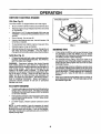
BEFORE STARTING ENGINE
GASOLINE RLLER CAP
OIL (See Fig. 5)
Your lawn mower is shipped withoutoil in the engine.
•
Be sure mower is level and area around oitfill is clean.
•
Removeengineoilcapwidipstickandfilltothefullline
on the dipstick.
•
Use 20 ozs. of oil. For type and grade of oilto use, see
"ENGINE" in Customer Responsibilities section of this
manual.
•
•
Pour oil slowly. Do not over fill.
Checkoil level before each use. Add oil if needed. Fill
to full line on dipstick.
To read proper level, tighten engine oilcap each time.
•
•
•
ENGINE OIL CAP
W/DIPSTICK
FIG. 5
Reinstall engine oil cap and tighten.
After the first two (2) hours of mowing, change the oil,
and every 25 hours thereafter. You may need to
change the oil more often under dusty,dirtyconditions.
MOWING TIPS
•
Undercertain conditions,such as very tall grass, itmay
be necessary to raise the height of cut to reduce
pushing effort and to keep from overloading the engine
and leaving clumps of grass clippings.
•
For extremely heavy cutting, reduce the width of cut
and raise the rear of the lawn mower housing one (1)
wheel adjuster setting higher than the front for better
discharge of grass.
•
For side discharge mowers, cutting in a counter-c!ockwise direction, starting at the outside of the area to be
cut, spreads grass clippings more evenly and puts less
load on the engine. To keep clippingsoff of walkways,
flower beds, etc., make the first cuts in a clockwise
direction.
GAS (See Fig. 5)
•
Fill gasoline tank with fresh, clean, unleadedgasoline.
DO NOT USE PREMIUM GASOLINE. BE CAREFUL
NOT TO OVER FILL TANK.
WARNING: Experience indicates that alcohol blended
fuels (called gasohol or using ethanol or methanol) can
attract moisture which leads to separation and formation of
acids during storage. Acidic gas can damage the fuel
system of an engine while in storage. To avoid engine
problems, the fuel system should be emptied before storage of 30 days or longer. Drain the fuel tank, start the
engine and let it run until fuel lines and carburetor are
empty. Use fresh fuel next season. See Storage Instructions for additional information. Never use engine or
carburetor cleaner products in fuel tank or permanent
damage may occur.
Keep top of engine around starter clear and clean of
grass clippingsand chaff. This will help engine air flow
and extend engine life.
TO START ENGINE
•
To start a coldengine, push primerfive (5) times before
trying to start. Use a firm push. This step is not usually
necessary when starting an engine which has already
run for a few minutes.
•
Hold operator presence control bar down to the handle
and pull starter handle quickly. DO NOT allow starter
rope to snap back.
•
To STOP engine, release operator presence control
bar.
NOTE: In cooler weather it may be necessary to repeat
priming steps. In warmer weather over priming may cause
flooding and engine will not start. If you do flood engine,
wait a few minutes before attempting to start and DO NOT
repeat priming steps.
8
ii ii
ii
CUSTOMER
iii1|i
RESPONSIBILITIES
i1|1111|11
ii
ii
O,.T .,°cosc.
.... ouL
i
, ,
,,,
.....
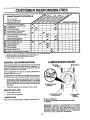
FILL IN DATES
AS YOU COMPLETE
Check for Loose Fasteners
Clean/Inspect
Grass Catcher
(If Equipped)
Clean Lawn Mower
WE Inspect/Clean
Drive Wheels
(Self-Propelled
Mowers)
R
sharpeniF_eplace
Mower Blade
_"___,_O__._._ _._
E
Replace Air Filter Paper Cartridge
1 - Change
2 - Service
_¢._:_t,_
O_
I_
J
K
v'
V"
.
..IV#
v'
I_
NE Check Engine Oil Level
Change Engine Oil ,..
G Clean Air Filter
| Inspect IVluffler
Replace Spark Plug
,_._
If
...
v'3
v'..
Lubrication Chart
Clean Battery/Recharge
IElectric,,,Start Mowers)
N
._'_.
,
v'
I_
If
I_
I_
.
1_=1.2
v'
v'2
,,
......
more often when operating under a heavy lead or in high ambient
more often when operating in dirty or dusty conditions.
IIIIIIII
temperatures.
3 - Replace blades more often when mowing in sandy soil.
4 - Charge 48 hours at end of season.
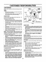
LUBRICATION CHART
GENERAL RECOMMENDATIONS
The warranty on this lawn mower does not cover items that
have been subjected to operator abuse or negligence. To
receive full value from the warranty, operatormustmaintain
mower as instructedin this manual.
(_WHEEL
ADJUSTER
) ENGINEOIL
Some adjustments will need to be made periodicallyto
properly maintain your unit.
All adjustments in the Service and Adjustments sectionof
this manual shouldbe checked at least once each season.
•
•
Once a year, replace the spark plug, clean or replace
air filter element and check blade forwear. A new spark
plug and clean!new air filter element assures proper
air-fuel mixture and helps your engine run better and
last longer.
Followthe maintenance schedule in this manual.
(_)BRAKE
SPRING
BRACKET
BEFORE EACH USE
•
Check engine oil level.
•
Check for loose fasteners.
(_)HANDLE
BRACKET
MOUNTING PIN
LUBRICATION
Keep unit well lubricated (See "LUBRICATION
(_) DISCHARGE
GUARD
HINGE PIN
(_)SPRAYLUBRICANT
CHART").
(_)REFERTO
SECTION.
CUSTOMER RESPONSIBILITIES"ENGINE"
IMPORTANT" DO NOT OIL OR GREASE PLASTIC WHEEL
BEARINGS.
VISCOUS LUBRICANTS
WILL ATTRACT
DUST AND DIRT THAT WILL SHORTEN THE LIFE OF
THE SELF LUBRICATING BEARINGS. IFYOU FEELTHEY
MUST BE LUBRICATED, USE ONLY A DRY, POWDERED
GRAPHITE TYPE LUBRICANT SPARINGLY.
9
CUSTOMER
RESPONSIBILITIES
ll==
LAWN MOWER
CRANKAFT
KEYWAY
BLADE
ADAPTER_
Always observe safety rules when performing any maintenance.
KEY
TIRES
•
Keep tires free of gasoline, oil, or insect control chemicals which can harm rubber.
•
Avoid stumps, stones, deep ruts, sharp objects and
other hazards that may cause tire damage.
BLADE
BLADE CARE
For best results, mower blade must be kept sharp.
place bent or damaged blades.
Re-
CRANKSHAFT
TO REMOVE BLADE (See Fig. 6)
Disconnect spark plug wire from spark plug and place
wire where it cannot come in contact with spark plug.
• Turn lawn mower on its side. Make sure air filter and
carburetor are up.
•
Use a wood block between blade and mower housing
to prevent blade from turning when removing blade
bolt.
HARDENED
WASHER
LOCK WASHER
TRAILING
EDGE
BLAD£ ADAPTER
FIG. 6
GEAR CASE
•
Protect your hands with gloves and/or wrap blade with
heavy cloth.
•
Remove blade bolt byturning counter-clockwise. Use
a 9/16" box or open-end wrench.
•
Remove blade and attaching hardware (bolt, lock
washer and hardened washer).
NOTE: Remove the blade adapter and check the key
inside hub of blade adapter. The key must be in good
condition to work properly. Replace adapter if damaged.
To keep your drive system working properly, the gear
case and area around the drive should be kept clean
and free of trash build-up. Clean under the drive cover
twice a season.
The gear case is filled with lubricant to the proper level
at the factory. The only time the lubricant needs
attention is if service has been performed on the gear
case.
If lubricant is required, use only Texaco Starplex Pro*
mium Grease, part no. 750369. Do not substitute.
TO REPLACE BLADE (See Fig. 6)
•
Position the blade adapter on the engine crankshaft.
Be sure key in adapter and crankshaft keyway are
aligned.
•
Position blade on the blade adapteraligningthetwo (2)
holes in the blade with the raised lugs on the adapter.
•
Be sure the trailing edge of blade (opposite sharp
edge) is up toward the engine.
•
Installthebladeboltwiththelockwasherandhardened
washer into blade adapter and crankshaft.
•
Use block of wood between blade and lawn mower
housing and tighten the blade bolt, turning clockwise.
•
The recommended tightening torque is 35-40 ft. Ibs.
IMPORTANT: BLADEBOLT IS GRADE 8 HEAT TREATED.
DRIVE WHEELS
Check front drive wheels each time before you mow to be
sure they move freely.
The wheels not turning freely means trash, grass cuttings,
etc. are in the drive wheel area and must be cleaned to free
drive wheels.
If necessary to clean the drive wheels, check both front
wheels.
NOTE: We do not recommend sharpening blade- but if you
do, be sure the blade is balanced.
TO SHARPEN BLADE
Care should be taken to keep the blade balanced. An
unbalanced blade will cause eventual damage to lawn
mower or engine.
•
The blade can be sharpened with a file or on a grinding
wheel. Do not attempt to sharpen while on the mower.
•
Tocheck blade balance, drive a nai! into a beam orwall.
Leave about one inch of the straight nail exposed.
Place center hole of blade over the head of the nail. If
blade is balanced, it should remain in a horizontal
position. If either end of the blade moves downward,
sharpen the heavy end until the blade is balanced.
•
Remove hubcaps, hairpin cotters and washers.
•
Remove wheels from wheel adjusters.
•
Remove any trash or grass cuttings from inside the
dust cover, pinion and/or drive wheel gear teeth.
•
•
Put wheels back in place.
If after cleaning, the drive wheels do not turn freely,
contact your nearest authorized service center.
GRASS
CATCHER
(If purchased as an accessory)
10
°
The grass catcher may be hosed with water, but must
be dry when used.
•
Checkyour grass catcher often for damage or deterioration. Through normal use it will wear. If catcher
needs replacing, replace only with a manufacturer
approved replacement catcher. Give the lawn mower
model number when ordering.
CUSTOMER
RESPONSIBILITIES
ENGINE
LUBRICATION
Use only high quality detergent oil rated with API service
classification SG. Select the oil's SAE viscosity grade
according to your expected operating temperature.
SAE VISCOSITY GRADES
4
I °F
-2_'
i°c_o"
0°
-2'o,._o
TEMPERATURE
_0 °
32°
40 _
G"
60 =
;oo
80 =
_o-
100 °
- CONTAINER
3'oo.'oo
RANGE...ANTICIPATED BEFORE NEXT OIL CHANGE
FIG. 7
NOTE: Although multi-viscosity oils (5W30, 10W30 etc.)
improve starting in cold weather, these multi-viscosity oils
will result in increased oil consumption when used above
32°F. Checkyour engine oil level more frequently to avoid
possible engine damage from running low on oil.
COLLAR
Change the oil after the first two hours of operation and
every 25 hours thereafter or at least once a year if the lawn
mower is not used for 25 hours in one year.
COUNTERCLOCKWISE
TO REMOVE
Check the crankcase oil level before starting the engine
and after each five (5) hours of continuous use. Tighten oil
plug securely each time you check the oil level.
SLOT
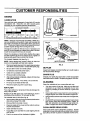
AIR FILTER
TO CHANGE ENGINE OIL (See Fig. 7)
NOTE: Before tipping lawn mower to drain oil, drain fuel
tank by running engine until fuel tank is empty.
•
MUFFLER
Inspect and replace corroded muffler as it could create a
fire hazard and!or damage.
Remove bottom oil drain plug.
SPARK PLUG
After oil has drained completely, replace oil drain plug
and tighten securely.
Change your spark plug each year to make your engine
start easier and run better. Set spark plug gap at .030 inch.
Refill engine with oil. Pour slowly. Do not over fill.
Fill to top of slot inside of filler hole.
CLEANING
Clean the underside of your mower after each use.
•
Turn lawn mower on its side. Make sure air filter and
carburetor are up. Clean the underside of your lawn
mower by scraping to remove build-up of grass and
trash.,
Reconnect spark plug wire to spark plug.
AIR FILTER
Your engine will not run properly and may be damaged by
using a dirty air filter.
Replace the air filter every year, more often if you mow in
very dusty, dirty conditions. Do not wash air filter.
TO CHANGE A1R FILTER (See Fig. 8)
•
Remove the air filter by tuming counterclockwise to the
stop and pul! away from collar.
•
Remove fitter from inside of cover.
•
;LOCKW]SE
TO TIGHTEN
FIG. 8
Disconnect spark plug wire from spark plug and place
wire where it cannot come in contact with spark plug.
Be sure lawn mower is on level surface.
Oil will drain more freely when warm.
Catch o11in a suitable container.
•
/
/
AIR FILTER COVER
Clean the inside of the cover and the collar to remove
any dirt accumulation.
Insert new filter into cover.
•
Put air filter cover and filter into collar aligning the tab
with the slot.
•
Push in on cover and turn clockwise to tighten.
•
Clean engine often to keep trash from accumulating. A
clogged engine runs hotter and shortens engine life.
•
Keep finished surfaces and wheels free of all gasoline,
oil, etc.
•
We DO NOT recommend using a garden hose to clean
lawn mower unless the electrical system, muffler, air
filter and carburetor are covered to keep water out.
Water in engine can result in shortened engine life.
CLEAN UNDER DRIVE COVER
11
Clean under drive cover at least twice a season. Scrape
underside of cover with putty knife or similar tool to remove
any build-up of trash or grass on underside of drive cover.
SERVICE AND ADJUSTMENTS
ii
CAUTION:
i
r
i
BEFORE PERFORMING ANY SERVICE OR ADJUSTMENTS:
,•
Release
control
bar. and all moving parts have completely stopped.
Make sure
the blade
•
Disconnect spark plug wire from spark plug and place where it cannot come in contact with plug.
LAWN MOWER
TO ADJUST
CUTTING
HEIGHT
See "TO ADJUST CU-I-IING HEIGHT" in the Operation
section of this manual.
DISCHARGE
I
I
GUARD
DRIVE
COVER
The discharge guard, attached to the dischargeopening of
your lawn mower, is provided to prevent the possibility of
injury resulting from objects being thrown out of the discharge opening into the operator mowing position. If the
discharge guard becomes damaged, it should be replaced.
TO REMOVE/REPLACE
BELT
PRESS
LL
DRIVE BELT
FIG- 9
(See Fig. 9)
•
•
Remove drivecover. Remove beltby pushingdown on
gear case pulley.
Turn lawn mower on its side with carburetor and fuel
cap up.
Remove blade.
•
Remove debris shield.
•
Remove belt from engine pulley on crankshaft.
•
•
Install new belt by reversingabove steps.
Always use factory approved belt to assure fitand long
life.
•
12
SERVICE AND ADJUSTMENTS
TO ADJUST
HANDLE
(See Figs, 10 Thru 12)
SHIPPING POSITION
Your lawn mower handle can be raised or loweredforyour
mowing comfort. Four (4) positionsare available: high,
medium high, medium low and low. Handles are shipped
mounted in the medium low position.
•
MEDIUM LOW
MEDIUM HIGH
To change from medium low to medium highposition,
the upper and lower handle sections will have to be
turned over (See Fig. 10B).
Remove the controls and operator presence control
bar from the upper handle.
Remove the starter rope guide from the lower handle.
•
•
•
•
Remove hairpin cotters.
Disconnectthe lower handle from the handle brackets
(See Fig. 12).
Turn the handle over and reassemble the hairpin
cotters that have been removed.
•
FIG. 10A
FIG. lOB
Reassemble the starter rope guide.
Reassemble the controls and the operator presence
control bar to the upper handle.
LOW
iiii
CAUTION: The operator presence control bar must pivot freely to permit blade
brake engagement when control bar is
released.
Do not
teners
holding
theovertighten
controls to the
the fasup-
_
per handle.
..,..
•
•
To change from medium low to high position only the
upper handle section will have to be turned over (See
Fig. 11A).
To change from medium low to low position, only the
lower handle section will have to be turned over (See
Fig. 11 B).
ENGINE
FIG. 11A
FIG. 11B
ENGINE SPEED
Your engine speed has been factory set. Do not attempt to
increase engine speed or it may result in personal injury. If
you believe that engine is running too fast or too slow, take
your mower to an authorized service center for repair and
adjustment.
LOWER HANDLE
SQUEEZE
TO REMOVE
CARBURETOR
Your carburetor has been preset at the factory and is not
adjustable.
HANDLE BRACKET
HAIRPIN CLIP
FIG. 12
13
ill
i, ..........................
STORAGE
Immediately prepare your lawn mower for storage at the
end of the season or if the unit will not be used for 30 days
or more.
ENGINE
FUEL SYSTEM
LAWN MOWER
IMPORTANT:
IT IS IMPORTANT TO PREVENT GUM
DEPOSITS
FROM FORMING
IN ESSENTIAL
FUEL
SYSTEM PARTS SUCH AS CARBURETOR, FUEL FILTER,
FUEL HOSE, OR TANK DURING STORAGE.
ALSO,
EXPERIENCE
INDICATES THAT ALCOHOL
BLENDED
FUELS (CALLED GASOHOL OR USING ETHANOL OR
METHANOL) CAN ATTRACT MOISTURE WHICH LEADS
TO SEPARATION AND FORMATION OF ACIDS DURING
STORAGE.
ACIDIC GAS CAN DAMAGE THE FUEL
SYSTEM OF AN ENGINE WHILE ]N STORAGE.
When lawn mower isto be stored for a period of time, clean
• it thoroughly, remove all dirt, grease, leaves, etc. Store in
a clean, dry area.
•
Clean entire lawn mower (See "CLEANING" in the
Customer Responsibilities section of this manual).
Lubricate as shown in the Customer Responsibilities
section of this manual.
Drain the fuel tank.
Be sure that all nuts, bolts, screws, and pins are
securely fastened. Inspect moving parts for damage,
breakage and wear. Replace if necessary.
Touch up all rusted or chipped paint surfaces; sand
lightly before painting.
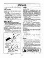
HANDLE
(See
Start the engine and let it run until the fuel lines and
carburetor are empty.
Never use engine or carburetor cleaner products in the
fuel tank or permanent damage may occur.
Use fresh fuel next season.
Fig. 13)
NOTE: Fuel stabilizer is an acceptable alternative in
minimizing the formation of fuel gum deposits during storage. Add stabilizer to gasoline in fuel tank or storage
container. Always follow the mix ratio found on stabilizer
container, Run engine at ]east 10 minutes after adding
stabilizer to allow the stabilizer to reach the carburetor. Do
notdrain the gas tank and carburetor ifusing fuel stabilizer.
You can fold your lawn mower handle for storage.
•
Squeeze the bottom ends of the lower handle toward
each other until the lower handle clears the handle
bracket, then move handle forward.
•
Loosen upper handle mounting bolts enough to allow
upper handle to be folded back.
IMPORTANT;
WHEN FOLDING THE HANDLE FOR
STORAGE OR TRANSPORTATION, BE SURE TO FOLD
THE HANDLE AS SHOWN OR YOU MAY DAMAGE THE
CONTROL CABLES.
•
ENGINE OIL
Drain oil (with engine warm) and replace with clean engine
oil. (See "ENGINE" in the Customer Responsibilities
section of this manual).
When setting up your handle from the storage position,
the lower handle will automatically lock into the mowing
position.
CYLINDER
LOWER HANDLE
•
Remove spark plug.
•
•
Pour one ounce (29 ml) of oil through spark plug hole
into cylinder.
Pull starter handle slowly a few times to distribute oil.
•
Replace with new spark plug.
PIN
OTHER
•
•
Replace your gasoline can if your can starts to rust.
Rust and/or dirt in your gasoline will cause problems.
•
If possible, store your unit indoors and cover itto give
protectionfrom dust and dirt.
•
Cover your unit with a suitable protective cover that
does not retain moisture. Do not use plastic. Plastic
cannotbreathe which allowscondensationto form and
will cause your unit to rust.
IMPORTANT: NEVER COVER MOWER WHILE ENGINE
AND EXHAUST AREAS ARE STILL WARM.
HAIRPIN
COTTER
OPERATOR PRESENCE
CONTROLBAR
Do not store gasoline from one season to another.
_
//
=
i
i
•
=
= iHll i.
i
CAUTION: Never storethe lawn mower
FOR STORA_
MOWING
ing where fumes may reach an open
with
in the
tank the
inside
a buildflamegasoline
or spark.
Allow
engine
to
cool before storing in any enclosure.
POSITION
LOWER HANDLE
FIG. 13
14
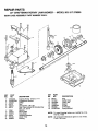
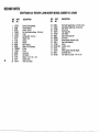
REPAIR PARTS
22" CRAFTSMAN
GEAR CASE ASSEMBLY
ROTARY LAWN MOWER
- - MODEL
NO. 917.378290
PART NUMBER 702511
17
15
10
18
|
.1
KEY
NO.
PART
NO.
1
2
3
4
5
6
17490416
137055X004
137053
57072
702710
48373
7
8
9
10
11
12
77881
137051
137074
57079
131484
700343
DESCRIPTION
Tapping Screw 1/4-20 x 1-1/4
Engagement Bracket
Shifter
Seal
Grooved Pin 1/8 x 5/8
Gear Case Halves Kit (Includes Key
Nos. 4, 5, and 7)
Bearing
Worm Shaft
Drive Shaft
Hardened Washer
Clutch Yoke
Bushing
KEY
NO.
PART
NO.
DESCRIPTION
13
14
15
16
17
18
19
86447
137050
750436X
750369
12000003
850848
81585X004
Rug
Helical Gear
Clutch Jaw
Grease
E-Ring
Hi-Pro Key
Spring Bracket
NOTE: To reseal housing halves use Locktite No. 515,
Part No. 77923
NOTE: All component dimensions given in U.S. inches.
1 inch = 25.4 mm
15
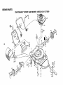
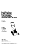
REPAIR PARTS
CRAFTSMAN
22" ROTARY LAWN MOWER - MODEL NO. 917.378290
43
34
I
33
39
L
42
41
62
51
56
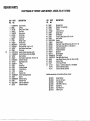
REPAIR PARTS
CRAFTSMAN
KEY
NO.
..,k
",4
1
2
3
4
5
6
7
8
9
10
12
13
14
15
18
19
22
23
24
25
26
27
28
29
33
34
35
36
38
39
4O
41
PART
NO.
133088X479
63601
702798
128415
103672X
851509
131959
85827
51793
136376
84676X479
74350424
750097
87930
701971X479
701969X479
128797
750097
87584X004
750149
12000014
87590
87593
87589
77400
85179
750085X007
84920
850855X004
87877
85021X004
62335
22" ROTARY LAWN MOWER - MODEL NO. 917.378290
DESCRIPTION
Upper Handle
Locknut
Zone Control Cable
Pop Rivet
Rope Guide
Control Bar
Handle Bolt
Cable Clip
Hairpin Cotter
Handle Knob
Lower Handle
Hex Head Bolt 1/4-20 x 1-1/2
Hex Washer Head Screw
Clip Guide
Handle Bracket Assembly (Left)
Handle Bracket Assembly (Right)
Rear Deflector
Hex Washer Head Screw #10-24 x 1/2
Deflector Bracket
Discharge Guard
E-Ring
Hinge Rod
Housing Bracket
Torsion Spring
Hubcap
Retainer Clip
Wheel Adjusting Bracket
Spacer
Selector Spring
Selector Knob
Axle Arm Assembly
Belleville Washer
KEY
NO.
42
43
44
45
46
47
48
49
50
51
52
53
54
55
56
57
59
60
62
63
64
68
---
PART
NO,
84921
88560
52160
751592
85463
59289
55187
53490
851201)(004
134612
850998
851084
850263
851074
850973
851514
700869X479
134027X479
48322
85543
87677
141133
141270
141271
DESCRIPTION
Shoulder Bolt
Wheel & Tire Assembly
Washer
Locknut 3/18-I6
Danger Decal
Flat Washer
Thread Cutting Screw 5/16-18 x 3/4
Hex Locknut
Washer
Debris Shield
Hex Head Thread Roiling Screw 3/8- 16 x 1-1/8
Hex Head Screw 3/8-24 x 1-3/8 (Grd. 8)
Helical Lockwasher
Hardened Washer
Blade 22"
Blade Adapter
Front Baffle
Rear Baffle (Not Shown)
Lawn Mower Housing (Incl. Ref. #46, 59 & 60)
Engine Pulley
Hi-Pro Key #HP 505
Engine- Craftsman Model No. 143.943806
Owner s Manual (English)
Owners Manual (Spanish)
Available accessories not included with lawn mower:
71 33072
71__.33623
7133500
7133300
7"133201
7133723
71 33316
Grass Catcher
Gas Can (2.5 gal.)
Fuel Stabilizer
SAE 30W Oil (20 oz.)
Mulcher Kit
High Wheel Kit
Mower Cover
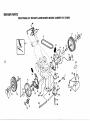
REPAIR PARTS
CRAFTSMAN
22" ROTARY LAWN MOWER MODEL NUMBER 917.378290
7
11
/
18
14
9
10
16
I
13
,--k
€o
15
!
14
34
28
41
15
9
4O
7
8
66
13
12
/8
REPAIR PARTS
CRAFTSMAN
KEY
NO.
.--i
1
2
3
4
5
6
7
8
9
10
11
12
13
14
15
16
18
25
PART
NO.
137076
48029
69180
750029
137078
700875
85179
77400
52160
86960
88558
12000057
137054
88080
88118
67725
87877
702179
22" ROTARY LAWN MOWER MODEL NUMBER 917.378290
DESCRIPTION
Control Cable Assembly
Control Head Kit
Locknut #10-24
Pan Head Machine Screw #10-24 x 2
V-Belt
Carriage Bolt 1/4-20 x 2
Retainer Clip
Hubcap
Washer
Nylon Bushing
Wheel & Tire Assembly
E-Ring
Pinion
Dust Cover
Felt Washer
Washer 1/2 x 1-1/2 x .134
Selector Knob
Drive Cover Decal
KEY
NO.
PART
NO.
26
27
28
31
32
33
34
35
36
37
38
40
41
55
56
87866
750097
137088
132010
137052
48323
850848
751809
702511
137090
STD541425
75192
751810
86012
851552
DESCRIPTION
Pan Head Tapping Screw #10-24 x 2-3/4
Hex Washer Head Screw #10-24 x 3/4
Drive Cover
Hex Flange Nut
Drive Pulley
Drive Control Cable Kit
Hi-Pro Key
Wheel Adjuster Assembly (Left)
Gear Case Assembly
Spring
Locknut 1/4-20
Spring
Wheel Adjuster Assembly (Right)
Driveshaft Cover
Pan Head Hi-Lo Screw #10-16 x 1/2
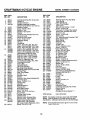
CRAFTSMAN 4-CYCLE ENGINE
I
II
MODEL
NUMBER
143.943806
III
\310
238
2O
CRAFTSMAN
4-CYCLE ENGINE
III
REF PART
NO. NO.
1
2
6
7
8
9
12
12B
14
15
16
17
18
19
2O
3O
4O
41
42
43
45
46
48
5O
52
69
70
72
73
75
8O
81
82
83
86
89
90
92
93
100
101
103
110
119
120
125
126
36470
26727
33734
34214A
33735
30200
33886
34695
28277
30589
31383A
31335
650548
36281
32600
35996
34514
34515
34516
32538B
32548B
32549B
28986
28987
28988
20381
30963B
32610A
27241
3599O
29914
35261
34311 D
30572
28833
27897
30574A
30590A
30591
30588A
650488
611004
611112
650815
650816
34443A
610118
650814
34961
36437
36474
36471
36472
29314B
29315C
130 6021A
MODEL
NUMBER
143.943806
III
REF PART
NO. NO.
DESCRIPTION
Cylinder (includes Ref. #2 and 20)
Dowel Pin
Breather Element
Breather Assembly (Includes
Reference Numbers 6, 8, 9 and 12)
* Breather Gasket
Screw #10-24 x 9/16
Breather Tube
Breather Tube Elbow
Washer
Governor Rod (Includes Ref. #14)
Governor Lever
Governor Lever Clamp
Screw #8-32 x 5/16
Extension Spring
Oil Seal
Crankshaft
Piston, Pin & Ring Set, Std. Size
Piston, Pin & Ring Set, .010" Over
Piston, Pin & Ring Set, .020" Over
Piston & Pin Assembly, Std. Size
Piston & Pin Assembly, .010" Over
Piston & Pin Assembly, .020" Over
(Assemblies Include Ref. #43)
Ring Set, Piston, Standard Size
Ring Set, Piston, .010" Oversize
Ring Set, Piston, .020" Oversize
Piston Pin Retaining Ring
Connecting Rod Assy. (Incl. #46)
Connecting Rod Bolt
Valve Lifter
Camshaft (BCR)
Oil Pump Assembly
* Mounting Flange Gasket
Mounting Flange (Incl. #72 thru 83)
Oil Drain Plug
Drain Plug Gasket
Oil Seal
Governor Shaft
Washer
Governor Gear Assy.(Includes #81)
Governor Spool
Screw 1/4-20 x 1-1/4
Flywheel Key
Flywheel
Beileville Washer
Flywheel Nut
Solid State Ignition
Spark Plug Cover
Screw, TorxT-15 #10-24 x 1
Ground Wire
* Cylinder Head Gasket
Cylinder Head
Exhaust Valve, Standard Size
Exhaust Valve, 1/32" Oversize
Intake Valve, Standard Size
Intake Valve, 1/32" Oversize
(All Valves Include Reference #151)
Screw 5/16-18x 1-I/2
135
150
151
169
172
178
182
184
185
186
189
190
191
192
193
194
195
207
216
223
224
238
239
241
245
250
26O
262
275
277
285
287
290
292
298
300
35395
35991
31673
27234A
32755
29752
6201
26756
31384A
32653
650839
35831
35040B
34966
34965
32309
610973
34336
33086
650451
34690A
65O932
34338
35797
35066
35065
36420A
650831
27181B
650795
35000
650926
3O705
26460
28763
34369B
301
305
306
307
309
310
313
327
370A
380
390
400
35355
3557-/
34265
35499
65O562
35578
34080
35392
36261
632646
590694
36475
RPM Settings:
DESCRIPTION
Resistor Spark Plug (RJ19LM)
Valve Spring
Valve Spring Cap
* Valve Cover Gasket
Valve Cover
Nut and Lock Washer 1/4-28
Screw 1/4-28 x 7/8
* Carburetor To Intake Pipe Gasket
Intake Pipe (Includes Ref. #224)
Governor Link
Screw 1/4-20 x 3/8
Brake Lever
S.E. Brake Bracket (Includes #195)
Brake Control Link
Brake Spring
Retaining Ring
Terminal
Throttle Link
R.PoM. Adjusting Lever
Screw 1/4-20 x 1
* Intake Pipe Gasket
Screw #10-32 x 49/64
* Air Cleaner Gasket
Air Cleaner Collar
Air Cleaner Filter
Air Cleaner Cover
Blower Housing
Screw 1/4-20 x 1/2
Muffler (Includes Reference #277)
Screw 1/4-20 x 2-1/4
Starter Cup
Screw #8-32 x 21/64
Fuel Line
Fuel Line Clamp
Screw #10-32 x 35/64
Fuel Tank (Includes Reference
Numbers 292 and 301)
Fuel Cap
Oil Fill Tube
* O-Ring
O-Ring
Screw #10-32 x 1/2
Dipstick
Spacer
Starter Plug
Instruction Decal
Carburetor (Includes Ref. #184)
Rewind Starter
Gasket Set
(Includes All Items Marked *)
High: 2900-3200
NOTE: This engine could have been built with 590686
Starter. Refer to design of air intake louvers for part
identification. Individual starter parts do not interchange.
NOTE: Atl component dimensions given in U.S. inches
1 inch = 25.4 mm
21
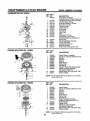
CRAFTSMAN
III
4-CYCLE ENGINE
IIII
CARBURETOR
MODEL
NUMBER
143.943806
I
l llI
NO. 632646
REF PART
NO. NO.
-632646
1
2
5
4St O
!
631615
631767
4
5
6
7
16
25
27
28
29
30
631184
631183
632504
650506
631807
631867
631024
632019
631028
631021
31
35
35A
40
44
48
631022
36045
632647
632503
27110
631027
i
REWIND STARTER
DESCRIPTION
Carburetor, Complete
(Includes #184 of Engine Parts List)
Throttle Shaft and Lever Assembly
Throttle Return Spring
Dust Seal Washer, Throttle
Dust Seal, Throttle
Throttle Shutter
Shutter Screw
Fuel Fitting
Float Bowl
Float Shaft
Float
Float Bowl "O" Ring
Inlet Needle, Seat & Ctip
(Includes Reference Number 31)
Spring Clip
Primer Bulb/Retaining Ring
Primer Bulb Filter
High Speed Bowl Nut
Bowl Nut Washer
Welch Plug, Atmospheric Vent
i
NO, 590694
REF PART
NO. NO.
-1
2
3
4
5
6
7
8
11
590694
590599A
590600
590696
590601
590697
590698
590699
590700
590695
12
13
590535
590701
DESCRIPTION
Recoil Starter, Complete
Spring Pin (Includes Reference #4)
Washer
Retainer
Washer
Brake Spring
Starter Dog
Dog Spring
Pulley & Rewind Spring Assembly
Starter Housing Assembly
(40 Degree Grommet)
Starter Rope (98" Long, 9/64" Dia.)
Starter Handle
NOTE: All component dimensions given in U.S. inches
1 inch = 25.4 mm
REWIND STARTER
NO. 590686
REF PART
NO, NO.
6
B
22
-1
2
3
4
5
6
7
8
590686
590599A
590600
590615
590601
590598
590616
590617
590618A
9
10
11
590619
590620
590687
12
13
590535
590452
DESCRIPTION
Recoil Starter
Spring Pin (Includes Reference #4)
Washer
Retainer
Washer
Brake Spring
Starter Dog
Dog Spring
Pulley Assembly (Includes
Reference Numbers 9 and 10)
Rewind Spring
Spring Cover
Starter Housing Assembly
(40 Degree Grommet)
Starter Rope (98" Long, 9/64" Dia.)
Starter Handle
NOTE: All component dimensions given in U.S. inches
1 inch = 25.4 mm
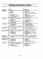
TROUBLESHOOTING
PROBLEM
|
CAUSE
CORRECTION
ml
Does not start
i
POINTS
1. Dirtyairfilte_
2. Out offuel.
3. Staiefuel.
4. WaterinfueL
1.
2.
3.
4.
5.
6.
7.
8.
9.
Spark prugwire is disconnected.
Bad spark plug.
Loose blade or broken biade adapter.
Control bar in released position
Control bar defective
5.
6.
7.
8.
9.
Clean/replace air filter.
Fill fuel tank.
Drain tank and refill with fresh clean fuel.
Drain fuel tank and carburetorand refill tank with fresh
gasoline.
Connect wire to plug.
Replace spark plug.
Tighten b_ade bolt or replace blade adapter.
Depress control bar to handle.
Replace control bar.
1.
Rear of lawn mower housing/blade dragging
in heavy grass.
Cut'dng too much grass,
Dirty air filter.
Buildup of grass, leaves and trash under mower.
Too much oil in engine.
Walking speed too fast.
1.
Set in "Higher Cut" position.
2,
3.
4.
5.
6.
Set in "Higher Cut= posit_on.
Clearffreplace air filter.
Clean underside of mower housing.
Check oil level.
Cut at slower walking speed.
ii1.1
Loss of power
2.
3.
4.
5.
6.
i
i1 i
i i
Poor cut - uneven
1.
2.
3.
4.
Worn, bent or loose blade.
Wheel heights uneven.
Low engine speed.
Buildup of grass, leaves, and trash under mower.
1.
2.
3.
4.
Replace blade. Tighten blade bolt.
Set all wheets at same height.
Set engine speed control In fast posi_on.
Clean underside of mower housing.
Excessive vibration
1.
2.
Worn, bent or loose blade.
Bent engine crankshaft.
1.
2.
Replace blade. Tighten blade bolt.
Contact an authorized service center/department.
I.
Engine flywheel brake is on when control bar is
released.
2.
3.
4.
Bent engine crankshaft
Blade adapter broken.
Blade dragging in grass.
1, Depresscontrolbarto upperhandle before
pulling starterrope.
2. Contactan authorizedservicecanter/department.
3. Replacebladeadapter.
4. Movelawnmowertocut grassor to hardsurface
to startengine.
1,
2.
Ddve wheels not turning w;th drive control engaged.
Belt not ddving.
1.
2.
Adjust or replace dr_ve control cable, if broken.
Put belt on pulleys or replace belts if broken.
Grass catoher not filling
(If so equipped)
1.
2.
3.
4.
Cutting height too low.
Lift on blade worn off.
Catcher not venting air.
Low engine speed.
1.
2.
3.
4.
Raise cutting height.
Replace blade.
Clean grass catcher.
Set engine speed control in fast position.
Hard to push
1.
2.
Grass is too high or wheel height is too low,
Rear of lawn mower housing/blade dragging
in grass.
Grass catcher too full.
Handle height position not right for you.
1.
2.
Raise cutting height.
Raise rear of lawn mower housing one (1)
setting higher.
Empty grass catcher.
Adjust handfe height to suit.
i
Starter rope hard to pull
||,1
Loss of drive
(Self-Propelled
Mowing)
el
I
i1,11
i
3.
4.
23
3.
4..
|
SE_/ Jk S
CRnFTSMilN®
OWNER'S
MANUAL
3.8 HORSEPOWER
22" SIDE DISCHARGE
POWER PROPELLED
ROTARY LAWN MOWER
Each lawn mower has its own model number.
gine has its own model number.
Each en-
The model number for your lawn mower will be found on a
decal attached to the rear of the lawn mower housing.
MODEL NO.
917.378290
The model number for your engine will be found on the
blower housing of the engine.
All parts listed herein may be ordered from any Sears,
Roebuck and Co. Service Center/Department and most
Retail Stores.
WHEN ORDERING REPAIR PARTS, ALWAYS GIVE THE
FOLLOWING INFORMATION:
IF YOU NEED
REPAIR SERVICE
OR PARTS:
• PRODUCT- LAWN MOWER
• MODEL NUMBER - 917.378290
FOR REPAIR SERVICE, CALL
THIS TOLL FREE NUMBER:
• ENGINE - CRAFTSMAN - MODEL NO. 143.943806
• PART NUMBER
1-800-4-REPAIR
• PART DESCRIPTION
(1-800-473-7247)
Your Sears merchandise has added value when you
consider Sears has service units nationwide staffed with
Sears trained technicians.., professional technicians
specificallytrained to insure that we meet our pledge to
you, we service what we sell.
FOR REPLACEMENT PARTS
INFORMATION AND
ORDERING, CALL THIS
TOLL FREE NUMBER:
1-800-FON-PART
(1-800-366-7278)
141270
I
II
Printed in U.S.A.
08/25/93
III
IIII
I
II
III
II
I