1
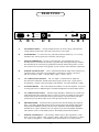
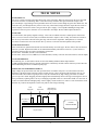
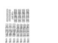
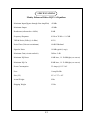
MANLEY
LABORATORIES, INC.
OWNER'S MANUAL
ENHANCED PULTEC
EQP1-A
EQUALIZER
MANLEY LABORATORIES, INC.
13880 MAGNOLIA AVE.
CHINO, CA. 91710 USA
TEL: (909) 627-4256
FAX: (909) 628-2482
email: [email protected]
http://www.manleylabs.com
CONTENTS
SECTION
PAGE
INTRODUCTION
3
EQ HINTS
4
FRONT PANEL
5
REAR PANEL
6
MAINS CONNECTIONS
7
TECH NOTES
8
TROUBLESHOOTING
9, 10
CURVES
11, 12
WARRANTY
13
WARRANTY REGISTRATION
14
APPENDIX:
WIRING YOUR OWN CABLES ?
TEMPLATE FOR STORING SETTINGS
INTRODUCTION
THANK YOU!...
for purchasing the Manley Laboratories Enhanced Pultec EQP-1A Equalizer. The Enhanced Pultec Equalizer
utilizes the original WESTERN ELECTRIC passive-equalization circuit found in the long-out-of-production
and justifiably famous PULTECS. According to experts, Western Electric developed the passive EQ in the 30's
to allow music to pass through a typical telephone system. This may help to explain the choice of curves and
frequencies - boost a bit of bottom, boost a bit on top and filter out the hiss. Western Electric also seem to have
brought us the balanced audio & the 600 ohm standard. Eugene Shenk of Pulse Technologies re-discovered
the EQ and added his vacuum tube gain make up amplifier. While Pultec sold a healthy number of units to
broadcast, when transistors came in, many jumped to the new technology and Pultec fell on hard times. It was
not until the mid 70's and early 80's with the big new recording studios that engineers and producers found that
nothing had the same magic low end that old Pultec tube EQs could give. Twenty years later, and they are still
favorites (along with old British console EQs) and today few understand why they sound so good. Its not "just"
the tubes.
We can offer a few good reasons. First - the EQ is passive. That means that the components involved have no
gain. A typical modern parametric EQ can use 10 to 20 op-amps, each with many, many transistors. Music
generally prefers a simple path with the fewest parts to pass a signal through. This also is one of the big
advantages to tube circuits - simplicity. The EQ uses a few capacitors, inductors and resistors (or pots). No
headroom problems, no crossover distortions, no slew induced distortions.
Second - The EQ curves tend to be wide. While not perfect for everything, wide, low-Q, low-resonance
frequency shaping is very musical and easy to use.
Third- Transformers can add a nice fat low end. That euphonic bottom was partially due to transformer
saturation. In other words the lower and louder a signal got, the more it saturated (added some extra harmonics
to the ultra lows where most speakers are deficient). It helps us percieve that there was some energy down there
without hearing the distortion as such. The older transformers suffered from wide band distortion and losses
in the highs. This is rarely wanted. Modern high quality transformers are much better in the highs and generally
much lower distortion, due to improvements in materials, but they can still saturate - the way we like.
Fourth - Op-amp circuits have limitations. They use negative feedback to control gain. Often enough, this can
cause a loss of transient accuracy and/or instability. Most op-amp EQ circuits rely on some very small signal
levels that are prone to cross-over distortions in the push-pull outputs. Older op-amps have slow PNP
transistors that began rolling off at a few hundred hertz causing crossover distortions. Headroom can be a hard
ceiling (+20 dBu) that gets nasty when significant amounts of boost are called for. All of this worsens when
driving capacitive wire or low impedances. The better solid state EQs are discrete with high voltage power
supplies for headroom. Our Langevin Pultec is that style. The Manley tube version beats it.
Manley uses an all-tube gain block with a +31 dBu capability and less than 10 dB of feedback. Four triodes
are used for "flat" class A gain stages and demonstrate the beauty of simplicity. We use a similar line amp in
our 40 dB Mic Preamps and Electro-Optical Limiters and some of our audiophile hi-fi preamps.
Our version of this classic EQ incorporates modern audiophile grade components with our proven line-amp
for absolute sonic beauty... Conductive plastic potentiometers and sealed gold-contact switches, polystyrene
and rolled film and foil capacitors, and a our own transformers combine with a regulated stiff power supply
and state-of-the-art tube circuitry to bring the PULTEC that is as good in the mids and highs as it has always
been in the lows. It is now commonly used in the best mastering suites and has become a standard (must-have)
item in studios world-wide. We added 8 frequencies and better interfacing, and it's only 1U !
Please take a few moments to read through this manual carefully as it contains information essential to proper
operation of this unit. Thank you again, and please enjoy!
3
EQ HINTS
We usually give a few hints about tricks commonly used with our products. With an
EQ of this type it is not so likely you need much help.
The most common question we get asked about our Pultecs is "Why both a boost and
a cut knob in the lows?". We don't know why it was designed that way for sure. It was designed
in the 1930's by Western Electric to improve music fed through telephone lines. We believe
it was done this way because it was the most practical in a simple passive design. This was
before op-amps and Baxandall type cut / boost circuits were common. We do know that most
engineers do use both knobs at the same time. Cutting a bit, boosting a bit, and the
combination gets the fat bottom they turn to the Pultec for. "Wouldn't they just cancel out?"
No, the shapes of the cut and boost are different and the result typically is boosted lows and
a dip in the mids but it depends on the relative settings. The slope of the low boost tends to
be steeper as well. We included a few pages of response curves to clarify this for you.
Vintage Pultecs are known for their usefulness on kick, bass, and raunchy guitars.
They are rarely used for vocals, mixes or sounds where transparent highs are important. The
Manley version, however, is often used for these purposes. It is featured in quite a few
mastering suites as one of the primary EQs. The difference is the Manley has better gain
make-up amps and fewer and better transformers. Here is the hint: for low end punch we
suggest using the XLR transformer inputs & outputs because the signal passes through two
transformers with a selected saturation characteristics. For situations where highs and fidelity
are most important you can bypass the transformers using the 1/4 inch phone jacks. You can
also use one transformer and bypass the other for something in-between. A little experimentation
when you first get the unit will go a long way in the years of use. The Manley EQs were never
intended as a clone of the original. We sought to improve them where we could. We knew
it was a good concept and, with permission, could produce this little gem.
The Bandwidth control (mid &high boost section) seems reverse to many. As one
turns the Bandwidth control clockwise the actual bandwidth increases - the "Q" is less. If one
is used to "Q" controls then it will seem reverse - but think of it as "bandwidth" not "Q". It
also boosts less dB's as bandwidth is increased but because the "area" is somewhat constant
it doesn't sound like lost boost. The bandwidth narrows slightly as frequency is increased.
Watch out boosting major amounts of low end when using most nearfield monitors.
Most don't have great response down there. One common technique is for engineers to watch
speaker excursion to get an idea how much lows they are putting on. How accurate is that?
It is not uncommon for an engineer to be surprised once they hear the tape in the car or on
a system with a sub woofer. The extreme lows and highs are the most likely part of a sound
to not "nail" because of monitors, fatigue, and the hype factor that is occasionally called for.
Best applications for this EQ? Important up-front sounds that a cheap EQ might
butcher just passing the signal. Low end sounds like kick and bass that need serious fatness
and punch & guitar amps that have lost that low thump we hear in the studio. Strong transient
sounds like shakers, tamborines, and cowbells that some solid state gear has a way of
smearing and turning into noise. Best time and place to shape the sound - before recording
and with mic technique. Then the EQ becomes a useful tool - not a needed crutch.
4
FRONT PANEL
IN
BOOST
SELECT
CUT
BANDWIDTH
D
E
SELECT BOOST
SELECT CUT
POWER
BYPASS
A
B
C
LOW FREQUENCY
SECTION
F
G
HIGH FREQUENCY BOOST
SECTION
H
I
J
K
HIGH FREQ. CUT
SECTION
A
IN / BYPASS - This switch in BYPASS mode bypasses the EQ section while the amplifier remains
in circuit.
B
L.F. BOOST - Shelf - Provides continuously variable BOOST from 0dB to +15dB to the selected low
frequency (control C). Check out the curves on pages 15 & 16.
C
LOW FREQUENCY SELECTOR - Used for both L.F. BOOST and/or CUT. For BOOST or CUT
this frequency is almost the maximum of the curve. With maximum boost (or cut), lower frequencies
may get 3 dB more boost (or cut).
D
L.F. CUT - Shel f - Provides continuously variable CUT from 0dB to +16dB to the selected low
frequency ( control C). Many use a combination of boost and cut to get an interesting shape. The typical
effect is boosed lows with a dip in the low mids or mids. Why ? Because the boost and cut are not mirror
images of each other. The cut stetches higher.
E
BANDWIDTH - This continuously variable control affects the width of the HIGH FREQUENCY
BOOST effect. Counter-clockwise (around 1) is narrow or a high Q. Clockwise is a larger bandwidth,
wider or lower Q. The maximum boost of 20 dB occurs at narrow bandwidths and goes to 13 or 14 dB
with wider bandwidth. Because the area stays somewhat constant it does not sound like lost boost. The
bandwidth also tends to get slightly narrower with higher H.F. BOOST frequencies - normal for
passive EQs. This knob may seem reversed if one is used to modern parametrics.
F
H.F. BOOST - Peaking - Provides Continuously variable BOOST from 0 to +20dB to the selected
high frequency (select control G). The maximum amount of H.F. BOOST is affected also by the
BANDWIDTH control. (see E)
G
HIGH FREQUENCY BOOST SELECT - Selects at which frequency maximum operation of the H.F.
BOOST section occurs. The frequencies are marked in KiloHertz.
H
HIGH FREQUENCY CUT - Shelf - Provides continuously variable CUT from 0 to -21dB of the
extreme high frequencies.
I
HIGH FREQUENCY CUT SELECT - Selects at which frequency the H.F. CUT control occurs.
The frequency is about half way down the curve (max =-21dB, at selected freq = -12 dB)
J
LED - When power is first turned on the LED is RED. This means that the EQ is muted until the tubes
are warmed up. It prevents thumps and pops. About 20 seconds later the LED turns GREEN and the
EQ will pass audio. This circuit is smart enough to ignore a quick black-out.
5
REAR PANEL
DIRECT
IN
CIRCUIT BALANCED UNBALANCED
OUTPUT
GROUND
180º
CHASSIS
A
B C
0º
D E
F
G H I
A
IEC MAINS SOCKET - Accepts standard 50/60 Hz AC mains voltage. Check that the
voltage indicated on the back is the same as the mains in your country.
B
FUSE HOLDER - To remove the fuse, push and turn the fuse holder cap. Use a 1 Amp
SLO-BLO fuse. Always replace fuse with same value and type.
C
GROUND TERMINALS - Use these to minimise hum. See troubleshooting section.
Normally these two terminals are joined by a "ground" strap. Moving this strap is similar to
disconnecting the AC mains 3rd pin ground but includes the chassis/rack ground. You can
also connect a wire from the "circuit ground" to your console in some situations. Experiment.
D
XLR BALANCED OUTPUT - This is a transformer balanced output which will drive any
impedance down to 600 ohms, but an impedance of 2000 ohms or greater is preferred.
Pin out is as follows: PIN1 = Ground, PIN2 = high (+), PIN3 = low (-).
E
1/4" UNBALANCED OUTPUT - The 1/4" output is a transformerless output and
disconnects the transformer & XLR output when a plug is inserted. Tip = Signal, Sleeve =
Ground, Ring = unused. Using mono plugs avoids mistakes. Use either output but not both.
F
GAIN SET PRESET - This control adjusts the feedback over the line amplifier. It is preset
for unity gain, however, additional gain is available through this screwdriver adjust control.
G
1/4" UNBALANCED INPUT - 5000 ohm input impedance, unbalanced. It is meant as an
input that bypasses the transformer. This is too low as a "direct" for guitars but can be great
with an effects pedal or preamp between the guitar and EQ. You may need the gain these
pedals often provide. Most synths can drive this input but also may be low level.
H
PHASE REVERSE - Switched in the UP position will retain the floating input signal in
phase. Switched in the DOWN position will reverse the phase of the floating input signal.
Switched in the MIDDLE position switches off the transformer and the high impedance
unbalanced 1/4" input is optimised. The 1/4" input is always on but not highest impedance
(5K) until the switch is in the middle position. The middle position kills the XLR in.
I
XLR BALANCED INPUT - Fully floating / balanced input. Input impedance is 5000
ohms. Pin out is as follows: PIN1 = ground, PIN2 = high, positive going phase (+), PIN3 =
low, negative going phase (-). The PHASE switch must be on the "0" or "180" position.
6
B
A
L
A
N
C
E
D
MAINS CONNECTIONS
Your Pultec has been factory set to the correct mains voltage for your country. The
voltage setting is marked on the serial badge, located on the rear panel. Check that this
complies with your local supply.
Export units for certain markets have a moulded mains plug fitted to comply with local
requirements. If your unit does not have a plug fitted the coloured wires should be
connected to the appropriate plug terminals in accordance with the following code.
GREEN/YELLOW
BLUE
BROWN
EARTH
NEUTRAL
LIVE
terminal
terminal
terminal
As the colours of the wires in the mains lead may not correspond with the coloured
marking identifying the terminals in your plug proceed as follows;
The wire which is coloured GREEN/YELLOW must be connected to the terminal in the
plug which is marked by the letter E or by the safety earth symbol or coloured GREEN
or GREEN and YELLOW.
The wire which is coloured BLUE must be connected to the terminal in the plug which is
marked by the letter N or coloured BLACK.
The wire which is coloured BROWN must be connected to the terminal in the plug
which is marked by the letter L or coloured RED.
Older units had a switch for 220/240 or 110/120 volt operation. While a nice
feature, it compromised the noise floor slightly. We now hardwire for each country
we send units to. So the few who move thier racks internationally have to use typical step-up step-down transformers that they are probably using anyways. The vast
majority who don't fly gear globally have got quieter units. It is also a bit safer. We
mark each unit on the back panel for the voltage it is wired for - if in doubt, please
check.
This unit (like most pro gear) is designed for third pin AC mains ground.
See the troubleshooting section if you usually use ground lift adapters ( 2 pin to 3
pin or "cheaters") . You can use the ground posts on the back of this unit rather
than that method. Using these posts are safer and gets better results in most situations. In some locales and situations, ground lift adapters may be illegal or cause
problems with insurance.
7
TECH NOTES
SWITCHING ON
The power switch is located on the right hand corner of the front panel. When one first turns on the power the LED
next to the switch is red, indicating "mute"- after about twenty seconds it turns green and audio can pass. This
prevents thumps or pops during warm-up and shut-down. The circuit is smart enough to ignore short black-outs. The
audio does not pass through the relay involved - the relay, when muted, simply shorts the output. Do not switch on
and off rapidly in succession as this is not good for the power supply. A recent update added high voltage shunt
regulators so that AC power variations were not reflected to the output. We also added output transformers.
TUBE LIFE
As with all tubes, their quality degrades with age. This is due to cathode emission, a natural process found in all
tubes. Excessive increase in noise (hiss) can indicate the need to replace a tube. Usually, the 5814/12AU7Awill be
the one to try first as this is the tube in the gain stage. The 6414 is the output tube. Microphonics are a natural
occurrence found to some extent in all tubes. We try our best to select the least microphonic tubes possible.
TUBE SUBSTITUTION
This circuit has been optimised around the 5814 and the military 6414 tube types. We also believe these are the best
tubes for your unit. Replacement tubes can be obtained from Manley Laboratories. However, if you're stuck in a
pinch, the following tubes are approved substitutes for this unit:
For the 5814: 12AU7WA, ECC82 (exact substitutes)
For the 6414: 12AT7, ECC81, 12BH7A (not exact substitutes, but they will work fine with a little less current output)
CUSTOM VERSIONS
For mastering use, we also build a custom version of the Manley Enhanced Pultec EQ which has
1/2dB switching BOOST and CUT controls replacing the continuously variable controls found in your unit. We also
build a Mastering Version of our Mid Frequency EQ.
SERVICING and TUBE REPLACEMENT
High voltages are present in this unit when powered and for 10 minutes after power is removed due to the slow
discharge of the high voltage capacitors. Before opening the top, remove the mains cable and let the unit "sit" for
about 10 minutes. Even then it is good practice to only use one hand in any high voltage gear and/or use rubber
gloves to prevent a shock. Wiggling the tubes slightly back and forth helps when removing or inserting them. Given
these precautions, replacing tubes is as easy as changing a light bulb. There is a metal "tube shield" over the 5814. It
is there to reduce both hum and light pickup. Turn it slightly counter-clockwise to remove it. Do not touch the circuit
board or any resistors and capacitors as there may still be some charge remaining.
5814
input tube
6414
output tube
MIT Multicap
output capacitor
Gain make-up
amplifier
POWER
TRANSFORMER
EQ SECTION
8
TROUBLE-SHOOTING
There are a number of possible symptoms of something not quite right, some may be interfacing, others we will touch
on as well. On the back panel are balanced and unbalanced inputs and outputs. Usually we connect balanced outputs to
balanced inputs (same with unbalanced) but usually we can also patch an unbalanced to balanced or balanced to unbalanced
with no problem (especially true with transformers) but some gear you can't. Check the manuals if you find a problem.
NO POWER, NO INDICATORS, NADA - Probably something to do with AC power. Is it plugged in? Check the fuse on
the back panel. A blown fuse often looks blackened inside or the little wire inside looks broken. A very blackened fuse is a
big hint that a short occured. Try replacing the fuse with a good one of the same value and size. If it blows too then prepare
to send the unit back to the dealer or factory for repair. The fuse is a protection device and it should blow if there is a problem.
If the unit works with a new fuse, fine. Check the MAINS VOLTAGE SELECTOR if one is fitted. Some of our models are
able to have them and some don't. It should be set correctly for your mains voltage.
LIGHTS BUT NO SOUND - First try plugging the in and out cables into some other piece of gear to verify that your wires
are OK. Assuming that it was OK into the other unit it probably is still a wiring thing. The XLRs are transformer balanced
(isolated / floating) that require the LOW or negative part of the signal on PIN 3 to be connected to something, even when
driving unbalanced inputs. With unbalanced sends or returns are used with the EQ balanced inputs/outputs then PIN 3 and
GROUND should be connected together. The EQ's unbalanced outputs kill the balanced XLR signals to provide a
transformerless audio path. Once again, when using a balanced to unbalanced (or vice versa) don't forget to have PIN 3
connected to the SLEEVE of the 1/4" plug.
LEVELS SEEM TO BE WRONG, NO BOTTOM - Several possible scenarios. Manley uses the professional standard of
+4 dBm = Zero VU = 1.23 volts AC RMS. A lot of semi-pro gear uses the hi-fi reference of -10 dBm = Zero VU. This is a
14 dB difference that will certainly look goofy and may tend to distort. Often there are switches on the semi-pro gear to choose
the pro reference level. We do not provide that kind of switch because of inevitable compromises in the signal path. If the
loss looks close to 6 dB and it sounds thin then one half of the signal is lost. The cause is probably wiring again. One of the
two signal carrying wires (the third is ground / shield on pin 1) is not happening. Check the cables carefully because
occasionally a cable gets modified to work with a certain unit and it seems to work but its wrong in other situations. If you
have two and only one EQ exhibits this problem, it may be a problem in that unit. See the next item.
SIGNAL GONE EVEN IN BYPASS - The signal goes through the tube stage in "Bypass". Let's assume wiring has been
eliminated as suspect. There is about a 98% chance it is a tube. If it were solid state you would generally send it back for repair.
Being a tube unit, you can probably find the problem and fix it in a few minutes. Not too many years ago, people (your parents)
could "fix" their own stuff by taking a bag of tubes down to the corner and checking said tubes on a tube tester. These are
practically extinct but no prob'. Be careful - there are some high voltages inside the chassis and tubes can get pretty warm
but if you can replace a light bulb you should be able to cruise through this. Before you remove a tube, just take a look at
them powered up. They should glow a bit and they should be warm. If one is not, you have already found the problem. The
tube's filament (heater) is burnt out or broken (like a dead light bulb). The other big visual symptom is a tube that has turned
milky white - that indicates air has gotten into the tube or we joke "the vacuum leaked out". Either way replace the tube. They
are not hard to find - even Radio Shack carries a fair tube stock and Manley can ship you a tested one. You can even pull a
tube or two from a guitar amp to verify "it was that one not glowing" but then get an exact replacement (substitution list on
previous page). Before you pull a tube, pull the power out, let the unit sit and cool and discharge for 10 minutes, then swap,
then power, then check. Gentle with those tubes, don't bend the pins by trying to insert them not quite right. A little rocking
of them as you pull them out or put them in helps. When the problem follows the tube you found the problem - a bad tube.
No soldering, no meters, one screwdriver - easy. The good news is "easy" the bad news is, tube life is not very predictable.
HUM - Once again - several possibilities - several cures. Most likely it is a ground loop. If you are using the 1/4" unbalanced
inputs, try the transformer XLRs. Balanced inputs can reject hum from ground loops, but it would be good to break the loop.
The two most common procedures are: try a 3 pin to 2 pin AC adapter (about a dollar at the hardware store) which is better
than messing up the power cable by bending the ground pin until it breaks off. Method two - cutting the shield on one side
of the cable. This is usually done at every female XLR to "break" all loops. You may get a loop simply from the rack. All
the other gear in the rack is "dumping" ground noise onto the rack rails. Try removing the EQ from the rack so that it is not
touching any metal. You may have cured a non-loop hum. Some gear radiates a magnetic field and some gear (especially if
it has transformers) might receive that hum. A little distance was all it took. A cool method of reducing all sorts of hum and
noise is to use the new 60-0-60 balanced AC power transformers available from Equi=Tech and Furman. It costs more but
works best. Hum might be because of the unbalanced input but this hints at ground loops and questionable wiring.
9
IT MAKES NOISES WHEN THE FRONT PANEL IS TAPPED - An easy one. Some tubes become microphonic over
time. That means they start acting like a bad microphone. Vibration has caused the supports for the little parts in the tube to
loosen and now the tube is sensitive to vibration. Easy - Replace the tube. Which one? The one that makes the most noise
when you tap it - probably the 5814. It will have to be on , connected and speakers up but not too loud (save the speakers).
IT GOT HISSY - Also easy. This is again a common tube symptom. You could swap tubes to find the culprit but an educated
guess is OK too. Generally the first tube in the path is the one with the most gain and dealing with the softest signals. The
usual suspect is the tube that is usually located closest to the front panel volume pot or the 5814. You may find that you need
to choose the quietest tube out of several of that type. We do that at the factory.
DISTORTION - This might be a tube. Swapping is a good way to find out. It may be a wiring thing or mismatch as well.
Wiring problems usually accompany the distortion with a major loss of signal. Mismatches are a bit tougher. Without even
explaining the term "impedance" it is enough to say that a lot of gear is simply not capable of driving pro levels and low
impedances. It will sound like lost headroom, early clipping, distortion on peaks. Often changing the order of processors will
do the trick. Another not so rare place to look is the patchbay, your settings, the meter levels - it happens. This unit has high
input impedances, low ouput impedances and more headroom than most gear but will lose some of that headroom into 600
ohm inputs found in vintage gear. You can usually remove that 600 ohm (termination) and be better off.
DC OR SOMETHING AT THE OUTPUT THAT IS INAUDIBLE - It only seems to occur with long cables. It happens
on an older unit but not on the newer one. Years ago we found a problem with our line driver section when it fed very long
or cheap wire. The output would tend to oscillate in the inaudible ultrasonic frequencies ( 200 kHz to 500 kHz) into high
capacitance like a long cable. We cured it by adding a simple 47 to 100 ohm resistor at the XLR. Newer units should not have
a problem but if you have an old one, we can FAX you a 25¢ fix. Real DC at the output would be such a rare find that we
would be pretty surprised. We use a $30 output cap to block DC. Most manufactures use a 30¢ electrolytic cap but we don't
like the sound or reliability of these. We also had some low level, low frequency output caused by AC mains fluxuations. We
cured that with a unique high voltage shunt regulator. Older units may can get this fitted if needed.
THE KNOBS "FEEL" LOOSE - This is a complaint that we get. We use Bourns conductive plastic pots. They are the best
sounding, most reliable pot that we know of. David showed us that they have less coloration than Penny & Giles faders on
big consoles. Unfortunately they "feel" loose. We could use cheap unsealed pots like most other companies but then we would
not "feel" so good about putting the Manley name on the panel. The only better solution we can offer is the detented Grayhill
11 position gold contact rotary switches that we use for the mastering versions. This will cost you. You may notice that we
are proud to share the name of the makers of the parts we use. A lot of research and listening goes into our choices. The name
on the front panel is also the name on the desk of the parts buyer.
WHAT CAN BE DONE TO MAKE A TUBE PROCESSOR LESS FRAGILE - There is a strange and false rumor about
tube gear being unreliable and fragile. They seem to forget about all those original Pultecs and LA-2As still in daily operation
after 30 or 40 years. Many of them have been abused beyond belief. At least 95% of the ones made are in full daily operation.
What about all those old tube guitar amplifiers still working hard after the all the miles in the back of a truck. Tube mics,
like all condensor mics, are a bit fragile but it has usually been the mic capsule or cables and not the tubes. Now how much
solid state gear from the 70's and 80's still works (or is worth using)? It would seem that 40 year old tube gear is more reliable
than 20 year old solid state and more useful. On the other hand, we expect much of the the new cheap gear to have a short
life whether it uses tubes or solid state. "Fragility" is a question of "build quality" far more than the technology used.
The only tried and true way to increase the reliabilty factor in tube or solid state gear is to buy the well made stuff and then
carry back-up units like every touring company. If you can't have a "spare" unit at least have a few spare tubes. Do
manufacturers of solid state say "carry a few transistors or IC's, or do they say "send the unit back with an approved RMA"?
We respect and use the some of the "old" techniques of manufacturing - using solid, thick metal chassis, hand
soldering, fewest possible connectors and "over-engineered" designs. We also get to use better parts than were available back
then. We can use conductive plastic sealed pots, gold contact jacks and switches, high temperature capacitors and more stable
1% tolerance parts. We can also use solid state where it is best used - in the power supply. Silicon diodes have some advantages
in some of our designs and we often use HexFets for regulators, with zeners.
We do all we can to make this unit not only reliable but also a unit you will enjoy for decades. We rarely get gear
back for repair and very, very rarely charge for anything except tubes. We used to give a "lifetime" free repair guarantee
(except tubes) which was expained as your lifetime and/or the person you may have sold the gear to. Pretty gutsy but it shows
how we feel the gear is gonna last. We officially modified our policy when more gear was becoming rentals and used live,
and almost industrially however we do believe in supporting our customers to every practical extent.
10
SPECIFICATIONS
Manley Enhanced Pultec EQP1-A Equalizer
Maximum Input (Bypass through Line Amplifier)
+30 dBv
Maximum Output
+30 dBv
Headroom (referenced to +4 dBv)
26 dB
Frequency Response:
10 Hz to 70 kHz +/- 0.5 dB
THD & Noise (1kHz @ +4 dBm)
.015%
Noise Floor (Gain set to minimum)
-80 dB Wideband
Signal to Noise
116 dB typical (A wgt)
Maximum Gain (via trim on back)
5 dB to -5 dB
Maximum EQ Boost
16 dB lows, 11- 20 dB highs (see curves)
Maximum EQ Cut
20 dB lows, 11- 21 dB highs (see curves)
Power Consumption
.35 Amps @ 115 VAC
Fuse
1 Amp Slo-Blo
Size (1U)
19" x 1.75" x 10"
Actual Weight
9 Lbs
Shipping Weight
12 Lbs
13
WARRANTY
All Manley Laboratories equipment is covered by a limited warranty against defects in materials
and workmanship for a period of 90 days from date of purchase to the original purchaser only. A
further optional limited 5 year warranty is available to the original purchaser upon proper
registration of ownership within 30 days of date of first purchase.
Proper registration is made by filling out and returning to the factory the warranty card attached to
this general warranty statement, along with a copy of the original sales receipt as proof of the
original date of purchase. Only 1 card is issued with each unit, and the serial number is already
recorded on it.
If the warranty registration card has already been removed then this is not a new unit, and is
therefore not warranted by the factory. If you believe this to be a new unit then please contact the
factory with the details of purchase.
This warranty is provided by the dealer where the unit was purchased, and by Manley Laboratories,
Inc. Under the terms of the warranty defective parts will be repaired or replaced without charge,
excepting the cost of tubes. No warranty is offered on tubes, unless:
1. a Manley Laboratories preamplifier is used with a Manley Laboratories amplifier, and
2. the warranty registration card is filled out.
In such a case a 6 month warranty on tubes is available with the correct recording of the serial
number of the preamplifier on your warranty registration card.
If a Manley Laboratories product fails to meet the above warranty, then the purchaser's sole
remedy shall be to return the product to Manley Laboratories, where the defect will be repaired
without charge for parts and labour. The product will then be returned via prepaid, insured freight,
method and carrier to be determined solely by Manley Laboratories. All returns to the factory must
be in the original packing, (new packing will be supplied for no charge if needed), accompanied by
a written description of the defect, and must be shipped to Manley Laboratories via insured freight
at the customer's own expense. Charges for unauthorized service and transportation costs are not
reimbursable under this warranty, and all warrantees, express or implied, become null and void
where the product has been damaged by misuse, accident, neglect, modification, tampering or
unauthorized alteration by anyone other than Manley Laboratories.
The warrantor assumes no liability for property damage or any other incidental or consequental
damage whatsoever which may result from failure of this product. Any and all warrantees of
merchantability and fitness implied by law are limited to the duration of the expressed warranty.
All warrantees apply only to Manley Laboratories products purchased and used in the USA.
Some states do not allow limitations on how long an implied warranty lasts, so the above
limitations may not apply to you. Some states do not allow the exclusion or limitation of incidental
or consequential damges, so the above exclusion may not apply to you.
This warranty gives you specific legal rights and you may also have other rights which vary from
state to state.
WARRANTY REGISTRATION
We ask that you please fill out this registration form and send the bottom half to:
MANLEY LABORATORIES
REGISTRATION DEPARTMENT
13880 MAGNOLIA AVE.
CHINO CA, 91710
Or you may fax this page to: (909) 628-2482
Registration entitles you to product support, full warranty benefits, and notice of product
enhancements and upgrades. You MUST complete and return the following to validate your
warranty and registration. Thank you again for choosing Manley.
MODEL MANLEY ENHANCED PULTEC EQ SERIAL No. PEQ____________
PURCHASE DATE ______________ SUPPLIER ______________________
-------------------------------------------------------------------------------------------------------PLEASE DETACH THIS PORTION AND SEND IT TO MANLEY LABORATORIES
MODEL MANLEY ENHANCED PULTEC EQ SERIAL No. PEQ____________
PURCHASE DATE ______________ SUPPLIER ____________________________
NAME OF STUDIO & OWNER _________________________________________
ADDRESS ___________________________________________________________
CITY, STATE, ZIP _____________________________________________________
TEL: ________________FAX:__________________email:_____________________
COMMENTS?? We welcome your feedback!________________________________
_____________________________________________________________________