1
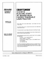
OWNER'S
MANUAL
MODEL NO.
917.254520
Caution:
Read and follow
all Safety Rules
and instructions
Before Operating
This Equipment
£RRFTSMRN®
12.
IC
ELECTRIC START
_"
DECK
5
TRANSAXLE
LAWN TRACTOR
•
,
=
•
•
Assembly
Operation
Maintenance
Service and Adjustment
Repair Parts
Sears, Roebuck and Co., Chicago, IL 60684 UoSoA.
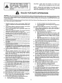
LOOK FOR THiS SYMBOL
TO POINT
OUT iMPORTANT
SAFETY
PRECAUTIONS. iT MEANS _ ATTENTION!
BE=
ALERT. I YOUR SAFETY
JS iN...........COME
VOLVED°
i
CAUTION:
LOOK FOR THIS WORD
iMPORTANT EQUIPMENT
TO POINT OUT
PRECAUTIONS.
NOTE: LOOK FOR THIS WORD TO POINT OUT IMPORTANT iNFORMATION ABOUT THE OPERATION
AND PERFORMANCE OF YOUR TRACTOR.
RULES FOR SAFE OPERATION
WARNING: This unit is equipped with an internal combustion engine and should not be used on or near any unimproved forest covered,
brush covered or grass covered land unless the engine s exhaust system is equipped with a spark attester meet ngapp cab eocal or area
laws (if any). If a spark arrester is used, it should be maintained in effective working order by the operator. (See REPAIR PARTS for part
number identification).
In the State of California the above is required by law (Section 4442 of the California Pub io Resources Code) Other States may have similar
laws. Federal laws apply on federal lands.
1.
2.
3.
4.
5.
6.
7.
Know the controls and how to stop quickly. READ THIS
OWNER'S MANUAL and instructions furnished with attachments.
Do not allow children to operate the machine. Do not allow
adults to operate it without proper instruction.
Do not carry passengers. Do not mow when children and
others are around.
Always wear substantial footwear. Do not wear oose fitting
clothing that could get caught in moving parts.
Keep your eyes and mind on your tractor mower and the
area being cut. Do not et other nterests distract you.
Do not attempt to operate your tractor or mower when not in
the driver's seat.
Always get on or off your tractor from the operator's left hand
side.
8.
Clear the work area of objects (wire rocks, etc.) which might
be p cked up and thrown.
g.
Disengage all attachment clutches before attempting to start
the engine.
10. Disengage power to attachments and stopthe engine before
leaving the operator's position.
1!. Disengage power to mower stop the engine and disconnect
spark plug wire(s) from spark plug(s) before cleaning, making
an adjustment, or repair. Be careful to avoid touching hot
muffler or engine components.
12. Disengage power to attachments when transperting or not in
use.
13. Take all pessible precautions when leaving the vehicle
unattended. Disengage the pewer take-off, lower the attachments, shift into neutral set the parking brake, stop the
engine, and remove the key.
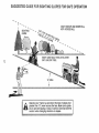
14. Do not stop or start suddenly when going uphill or downhill
Mow up and down the face of slopes (not greater than 15°)
never across the face. Refer to page ;47. "'
15. Reduce speed on slopes and make turns gradually to prevent
tipping or loss of control. Exercise extreme caution when
changing direction on slopes.
1& Whi{e going up or down slopes, place gear shift centre lever
in 1st gear position to negotiate the slope without stopping.
17. Never mow in wet or slippery grass, when traction is unsure,
or at a speed which could cause a skid.
18. Stay alert for holes in the terrain and other hidden hazards.
Keep away from drop-offs.
19. Do not drive too close to creeks, ditches, and public highways.
20. Exercise special care when mowing around fixed objects in
order to prevent the blades from striking them. Never deJiberately run tractor or mower into or over any foreign objects.
21. Never shift gears until tractor comes to a stop.
22. Never place hands or feet under the mower, in discharge
chute, or near any moving parts while tractor or mower is
running. Always keep clear of discharge chute.
23. Use care when pulling loads or using heavy equipment.
a.
Use only approved drawbar hitch points.
b. Limit loads to those you can safely control.
c.
d.
Do not turn sharply. Use care when backing.
Use counterweight or wheel weights when suggested in
owner's manual.
24. Watch out for traffic when crossing or near roadways.
25. When using any attachments
never direct discharge of
mater al toward bystanders nor allow anyone near the vehicle while in operation.
26. Handle gasoline with care - it is highly flammable.
a. Use approved gasoline containers.
b. Never remove the fuel cap of the fuel tank or add
gasoline to a running or hot engine or an engine that has
not been allowed to cool for several minutes after running. Never fil! tank indoors. Always clean up spilled
gasoline.
c. Open doors if the engine is run in the garage - exhaust
fumes are dangerous. Do not run the engine indoors.
27. Keep the vehicle and attachments in good operating coad t on, and keep safety devices in place and working.
28. Keep all nuts, bolts, and screws tight to be sure the equipment is in safe working condition.
29. Never store the equipment with gasoline in the tank inside a
building where fumes may reach an open flame or spark.
Allow the engine to cool before storing in any enclosure.
30. To reduce fire hazard, keep the engine free of grass, leaves,
or excessive grease. Do not clean product while engine is
running.
31. Except for adjustments, DO NOToperate engine if aircleaner
or cover directly over carburetor air intake is removed.
Removal of such part could create a fire hazard.
32. Do not operate without a muffler, or tamper with exhaust
system. Damaged mufflers or spark arresters could create a
fire hazard. Inspect periodically and replace if necessary.
33. The vehicle and attachments should be stopped and ino
spected for damage after striking a foreign object, and the
damage, should be repaired before restarting and operating
the equBpment.
34. Donotchangetheenginegovernorsettingsoroverspeedthe
engine; severe damage or injury may result.
35. When using the vehicle with mower, proceed as follows:
a. Mow only in daylight or in good artificial light.
b. Shut the engine off when unclogging chute.
c. Check the blade mounting bolts for proper tightness at
frequent intervals.
3& Do not operate the mower without the entire grass catcher,
on mowers so equipped, or the deflector shieJd in place.
37. Disengage power to mower before backing up. Do not mow
Jn reverse unless absolutely necessary and then only after
careful observation of the entire area behind the mower.
38. Under normal usage the grass catcher bag material is subject
to deterioration and wear. it should be checked frequently for
bag replacement Replacement bags should be checked to
ensure com_iance with the original! manufacturer's recommendations or specifications.
CONGRATULATIONS
on your purchase of a Sears
Lawn Tractor.
It has been designed, engineered and
manufactured to give you the best possible dependability
and performance.
Should you experience any problem
you cannot easily remedy, please contact your nearest
Sears Service Department.
We have competent, welltrained technicians and the proper tools to service or
repair this unit.
MAINTENANCE
THE SERIAL NUMBER
MODEL PLATE UNDER
AGREEMENT
A Sears Maintenance Agreement is available on this
_roduct. See the nearest Sears store or service center
r details.
CUSTOMER
DATE OFPURCHASE
WiLL BE FOUND
THE SEAT.
ON THE
YOU SHOULD RECORD THESE NUMBERS
KEEP FOR FUTURE REFERENCE.
AND
RESPONSiBiLITIES
Read and retain this manual. Study and observe the safety rules. Always use care when using your tractor. Always
keep your tractor and mower clean. Follow a regular schedule in maintaining, caring for, and using your tractor. A weft
cared for tractor will run better and last longer.
A TTACHMENTS
This unit can use many attachments now available at your Sears store. It cannot use attachments that engage the ground
fike a plow, harrow, cultivator, or tiller. See page 46 for a list of available attachments.
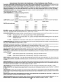
LiMiTED TWO YEAR WARRANTY
ON ELECTRIC START RiDiNG EQUIPMENT
For two years from date of purchase, when this riding equipment is maintained, lubricated, and tuned up according
to the operating and maintenance instruction in the owner's manual, Sears will repair free of charge any defect in
material or workmanship in this electric start riding equipment.
This warranty excludes blade(s), blade adapter(s), spark plug(s), air cleaner and belt(s), which are expendable and
become worn during normal use.
This warranty does not cover:
• Tire replacement or repair caused by punctures from outside objects (such as nails, thorns, stumps, or
glass); and
o repairs necessary because of operator abuse or negligence, including the failure to maintain the equipment according to instructionscontained in the owner's manual; and
o riding equipment used for commercial or rental purposes.
FULL 90 DAY WARRANTY ON BATTERY
For 90 days from the date of purchase, if any battery included with this riding equipment proves defective in material
or workmanship and our testing determines the battery will not hold a charge, Sears will replace the battery at no
charge.
WARRANTY SERVICE IS AVAILABLE BY CONTACTING THE NEAREST SEARS SERVICE CENTER DEPARTMENT IN THE UNITED STATES. This warranty applies only while this product is in use in the United States.
This warranty g_ves you specific legat rights, and you may also have other rights which may vary from state to state.
SEARS, ROEBUCK and CO., D/731CR-W, Sears Tower, Chicago, IL 60684
_DO
NOT OVERLOAD TRACTOR 8Y TOWRNG WEIGHTS GREATER THAN 150 POUNDS (68 KG).
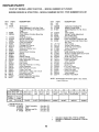
iNDEX
A
Adjustments:
Brake ..................................... 14
Carburetor ............................. 18
Mower Drive Belt ................... 22
Mower
Front-To-Rear ................... 23
Side-To-Side ..................... 22
Throttle Control Cable ........... 17
Air Cleaner ................................... 16
Air Screen, Engine ....................... 16
Assembly .................................. :. 5-9
Attachments ................................. 48
B
Battery:
Charging ............................ 7, 17
Cleaning ................................ 15
Installation ............................... 8
Levels .................................... 15
Preparation .............................. 7
Starting with Weak Battery .... 17
Sto rage .................................. 23
Terminals ............................... 15
Belt:
Motion Drive
Removal/Replacement
..... 19
Mower Drive
Removal/Replacement
..... 22
Adjustment ........................ 22
Blade:
Sharpening ............................ 14
Replacement .......................... 14
Brake Adjustment ......................... 14
C
Carburetor Adjustment ................. 18
Controls, Tractor ............................ 9
Cutting Level, Mower .............. 12,22
E
Engine:
Air Screen .............................. 16
Oil Change ............................. 15
Oil Level ................................. 16
Oil Type ................................. 16
Preparation ............................ 10
Repair Parts ...................... 42-45
Starting .................................. 11
Storage .................................. 23
F
Filter:
Air Cleaner ............................. 16
Fuel ........................................ 18
Fuel:
Type ....................................... 10
Sto rage .................................. 23
Fuse ............................................. 19
H
Hood Removal/Installation
........... 20
L
Leveling Mower Deck ................... 22
Lubrication:
Chart ...................................... 24
Tractor Pivot Points ............... 17
M
Maintenance ................................ 13
Air Cleaner ............................. 16
Foam Pre-cleaner ............. 16
Air Screen, Engine ................. 16
Battery ................................... 15
Blade Sharpening .................. 14
Brake Adjustment .................. 14
Engine Oil .............................. 16
Fuel Filter ............................... 18
Lubrication Chart ................... 24
Spark Plugs ........................... 18
Tire Care ............................. 8,14
Mower:
Adjustment, Front-to-Rear ..... 23
Adjustment, Side-to-Side ....... 22
Blade Sharpening .................. 14
Blade Replacement ............... 14
Cutting Level ..................... 12,22
Installation ............................. 21
Operation ............................... 11
Removal ................................ 21
Mowing Tips ................................. 12
Muffler ..........................................
17
Spark Arrester .................... 2,32
O
Oi!:
Cold Weather Conditions ....... !6
Engine ................................... 16
Storage .................................. 23
Operation .................................. 9-12
Operating Your Mower .......... 1 !
Operating Your Tractor .......... 11
Starting the Engine ................ 11
Stopping Your Tractor ........... 10
Tractor Operation on Hills ...... 12
Options:
Attachments ........................... 46
Spark Arrester .................... 2,32
P
Parking Brake ................................ 9
Parts Bag .................................... 5-6
Parts, Replacement/Repair ..... 28-45
R
Repair and Adjustments .......... 14-24
Blade ...................................... 14
Carburetor ............................. 18
Fuse ....................................... 19
Hood Removal/Installation ..... 20
Motion Drive Belt
Removal/Replacement
..... 19
Mower Drive Belt
Removal/Replacement
..... 22
Mower Adjustment
Front- to-Rear ................... 23
Side-to-Side ...................... 22
Mower Removal ...... _.............. 21
Tire Care ....... :........................ 14
Repair Parts ............................ 28-45
S
Safety Rules ...................................
Seat ................................................
Service Record .............................
Slope Guide Sheet .......................
Spark Plugs ..................................
Speed Control Chart ....................
Starting the Engine .......................
Steering Wheel ..............................
Stopping the Tractor .....................
Sto rage .........................................
2
8
13
47
18
12
11
7
10
23
T
Throttle Control Cable
Adjustment ............................. !7
Tires ..........................................
8, 14
Trouble Shooting Chart ........... 25-26
Transaxle:
Repair Parts ...................... 40-41
Transporting ................................. 12
W
Warranty ......................................... 3
Wiring Schematic ......................... 27
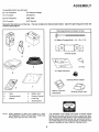
ASSEMBLY
To assemble tractor you wifl need:
12) 7/16" wrenches
Tire Pressure Gauge
11) 1/2" wrench
Screwdriver
(2) 9/16" wrenches
UtiRy Knife
(1) 3/4" wrench
5/16" Wrench
Take all of the items out of the box. The box contains the _tems shown beiowo Open the parts bag and check the
contents (see page 6).
Parts bag contents not shown full size
(2) Battery Carriage Bolts - 1/4 -20
x 7-1/2
C
D
Terminal Guard
G
A
(2) Keys
15 ° Slope Instruction
B
Steering Wheel Adapter
F
a.
Seat
d.
Battery Acid
b.
Steering wheel
e.
Owner's Manual
c.
Battery
f.
Parts Bag
g.
Steering Boot
NOTE:
Battery Caps and
instructions
RIGHT HAND(R.H.) AND LEFT HAND (L.H.) ARE
DETERMINED FROM OPERATOR'S POSITION
WHILE SEATED ON THE TRACTOR.
Steering Wheel Insert
The operation of any tractor can result in foreign objects
thrown into the eyes, which can result in severe eye damage. Always wear safety glasses or eye shields before starting your tractor and while moving. We recommend Wide Vision Safety Mask for over the spectacles or standard safety
glasses, available at Sears Retail or Catalog Stores.
5
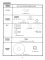
.... ASSEMBLY
ASSEMBLY
LOCATION
PARTS
BAG CONTENTS
SHOWN
FULL SiZE
BATTERY
(2) Wing Nut 1/4-20
BATTERY
TERMINALS
©
(2) Hex Bolt 1/4-20 x 3/4
_
(2) Lock Washer
1/4
(2) Washer 9/32 x 5/8 x !6 Ga.
G
(2) Hex Nut 1/4-20
SEAT
(1) Adjustment Bolt
(1) Lock Washer 1/2
(1) Washer 17/32 x
1-3/16 x 12 Ga.
(1) Shoulder Bolt 5/!6-18
STEERING
BUSHING
(2) Sheet Metal Screw 10-16 x 1/2 ABTBS
STEERING
WHEEL
(1) Locknut
(1) Washer 2-1/4
6
1/2-20
ASSEMBLY
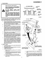
!. Prepare B_tery
WEAR EYE AND FACE SHIELD,
CUT AWAY ViEW
WASH HANDS OR CLOTHING IMMEDIATELY iF ACCIDENTALLY iN CONTACT
WiTH BATTERY ACID.
DO NOT
CHARGED
PLOSIVE.
SMOKE.
BATTERY
BATTERY
CAP
FUMES
FROM
ACID ARE EX-
READ THE iNSTRUCTiONS iNCLUDED
WiTH THE BATTERY VENT CAPS iN
THE BAG OF PARTS. ALWAYS WEAR
GLOVES, CLOTHING AND GOGGLES
TO PROTECT YOUR HANDS, SKiN AND
EYES.
FIGURE 1
Fill and charge battery (before installing). NOTE: SEE DETAILED iNSTRUCTiONS
PACKAGED WITH BATTERY
VENT CAPS FOUND IN BAG OF PARTS.
a.
b.
c.
d.
e.
f.
Fill each cel! with battery acid. Add the acid until it
reaches the bottom of the vent tubes (Fig. 1). Do not
add the acid beyond this level or the addffional acid
can come out when the battery is charged.
After ceils are filled, tilt battery from side to side to
release air bubbles.
Allow battery to stand and settle for at least thirty
minutes. If the level of acid falls below the point described in step (a), add more acid until the correct
level is reached. Install the battery caps, found inthe
bag of parts, to cover the vent tubes, Wash the top of
the battery with water to remove any acid, then wipe
dry.
Check battery case for leakage to make sure that no
damage has occurred in handling.
Neutralize excess battery acid for disposal by add=
ing it to 2 gallons (7 litres) ofwater in a five gallon (20
litres) plasticcontainer. Stir with awooden or plastic
paddle while adding baking soda until the addition of
more soda causes no more foaming.
tt is recommended that the battery be charged before use. Use a 12 volt battery charger. Charge battery at a rate of 6 amperes for 1 hour. NOTE: OBSERVE SAFETY PRECAUTIONS, LISTED IN BOX
ABOVE, REQUIRED FOR BATTERY CHARGING.
Check the acid level after the battery is charged. If
the acid has fallen below the correct level, add distilled or iron free water.
i
qlm
STEERING
V,
mEEL
ADAPTER
STEERING
BOOT
STEERING
BUSHING
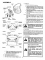
2. Unpack Tractor
a.
Cut down four corners of the carton with utility knife
and fold down sides.
b.
Disengage parkir_j brake and position front wheels
straight ahead (see page 9).
install steering wheel
c.
1.
2.
3.
4.
STEERING SHAFT
(REC'D. POSiTiON)
STEERING SHAFT
(iNST. POSITION)
FIGURE 2
Slide the steering bushing over the steering
shaft (Fig. 2).
Position steering shaft forward until screw holes
in dash line up with steering bushing, install two
(2) screws (Fig. 2).
Position steering boot over steering shaft.
Place bottom of steering boot over two slots in
dash (Fig. 2).
5.
7
Push steering boot down into aligning slots on
dash.
6.
Place steedng wheel adapter on steering shaft.
7.
With front wheels pointed straight ahead, place
steering wheel on steering wheel adapter. Bars
of steering wheel should point straight across
tractor.
ASSEMBLY
3. Instal| Seat
SEAT
\
a,
Remove cardboard from seat pan.
b_ Place seat on seat pan. S_rew adjustment bolt, k)ck
SEAT PAN
SHOULDER
BOLT
C.
shoulder bolt and washers found in bag of parts
(shown full size on page 6).
Tighten shoulder boif using a 1/2" wrench. NOTE:
THE SHOULDER BOLT WILL BE LOOSE IN THE
SEAT PAN SLOT.
d.
TirgshtceunraeldvJUstment
bo,, lock washer and flat wash-
ADJUSTMENT
BOLT
NOTE: SEAT POSITION SHOULD BE ADJUSTED FOR=
WARD OR BACKWARD SO THAT THE OPERATOR CAN COMFORTABLY
REACH CLUTCH/
BRAKE PEDAL AND SAFELY OPERATE TRACTOR.
LOCK
WASHER
FLAT
WASHER
e.
Place seat in operating position. Sit on the seat and
press clutch/brake pedal all the way down. tf operating pos'_ion is not comfortable, adjust seat.
f.
To adjust: raise seat. Loosen adjustment bolt. Slide
seat to desired position. Tighten adjustment bolt securely.
FIGURE 3
POSITIVE
TERh
WASHER
WASHER
NEGATIVE
HEX BOLTS
POSITIVE
CABLE
(RED)
_
ADJUSTMENT BOLT, LOCK WASHER
AND FLAT WASHER MUST BE TiGHTENED SECURELY TO PREVENT MOVEVENT OF SEAT.
_ NEGATIVE
CABLE
(BLACK)
4. Check Tires
FIGURE 4
TERMINAL
GUARD'--
WiNG NUT
TRAY_.
Check the air pressure in the tires. Tires with too much air
pressure will cause the unit to fide rough. The wrong air
pressure will also keep the mower from cutting level. The
correct air pressure is shown on the side of the tires. If the air
HEX NUTS
WiNG NUT
__
5. Instait Battery
!
_ACCESS
WEAR EYE AND FACE SHIELD.
"__
FIGURE 5
WASH HANDS OR CLOTHING IMMEDiATELY IF ACCIDENTALLY IN CONTACT
WITH BATTERY ACID,
"KEY
DRAIN TUBE
HOLE
DO NOT
CHARGED
PLOSIVE.
8.
Place 2 1/4" diameterwasheron
steering shaft
and install a 1/2" Iocknut (washer and Iocknut
found in bag of pads).Tighten securely.
9.
Snap insert into steering wheel.
e.
Remove plastic on tractor hood.
Raise attachment lift handle (see page 9).
f.
RofJTractor off skid. Be careful of staples in skid.
d_
SMOKE.
BATTERY
FUMES
FROM
ACID ARE EX-
READ THE INSTRUCTIONS
INCLUDED
WITH THE BATTERY VENT CAPS IN
THE BAG OF PARTS. ALWAYS WEAR
GLOVES, CLOTHING AND GOGGLES
TO PROTECT YOUR HANDS, SKiN AND
EYES.
8
ASSEMBLY
a.
b.
Lift seat (Fig. 3).
Lower battery into fenderwell with battery terminals
toward front of tractor (Fig. 4). Make sure battery
rests in battery tray (Fig. 5).
d.
NOTE:
BE SURE BATTERY DRAIN TUBE IS SECURELY
ATTACHED TO BATTERY TRAY DRAIN (Fig. 5).
e.
_
f.
,_
|
PO_IVlINAL
AWL,
NECTEDFIRST
MUST BECONTO PREVENT SPARKS
_
g.
|
h.
C.
Connect RED battery cable to positive (+) battery
terminal with hex bolt, flat washer, lock washer and
hex nut (shown full size on pg. 6) found in bag of
parts. Tighten securely with two 7/16" wrenches.
(Fig. 4).
Connect BLACK ground cable to negative (-) bat-
i.
j.
terminal
withhex
remaining
hex full
bolt,size
flaton
washer,
washer and
nut (shown
pg. 6)
found in bag of parts. Tighten securely (Fig. 4).
To prevent corrosion, apply grease to the battery
terminals after installing cables.
Slide two battery bolts through terminal guard and
start the wing nuts onto the threads (Fig. 5).
Position terminal guard over battery as shown (Fig.
5) and align bolt heads with key holes next to battery
tray (Fig.5).
Lower bolt heads into key holes and slide square
shafts of bolts into slots of key holes (Fig. 5).
Tighten wing nuts.
Close terminal access doors.
CAUTION:
DO NOT START ENGINE UNTIL YOU HAVE
REVIEWED THE OPERATION SECTION OF
THIS MANUAL.
LIFT LEVER PLUNGER
ATTACHMENT
CLUTCH
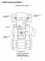
OPERATION
IGNITll
ATTACHMENT
LiFT LEVER
LIGHT SWITCH
VENT SLOTS
THR(
CONTROL
CLUTCH/BRAKE
PEDAL
MOWER DECK
HEIGHT
PARKING BRAKE
GEARSHIFT LEVER
NEUTRAL LOCK OUT POSITION
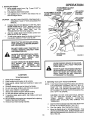
KNOW YOUR TRACTOR
ATTACHMENT CLUTCH LEVER: Push lever upto engage
attachment. There will be an engine hesitation as the clutch
engages.
ATTACHMENT LIFT LEVER: Use the attachment lift lever
to raise and lower the attachment mounted to your tractor.
Pull lever back slightly and push button, then move the lift
lever forward to lower attachment.
CLUTCH/BRAKE PEDAL: The pedal has 2 functions; a
clutch and a brake. To engage the brake push the pedal
completely down.
HEIGHT ADJUSTMENT:
Use the height adjustment slots
to adjust the mower height. Push the attachment rift lever
plunger down and position the attachment lift lever into the
desired slot. Release rift lever plunger.
GEARSHIFT: Press the clutch/brake pedal down firmly and
move gearshift lever to desired speed.
iGNiTiON: Place key in ignition and turn to the right to start.
The switch spring returns from the start position.
LIGHT SWITCH: Turns the headlights on and off.
PARKING BRAKE: To set the parking brake, push the
clutch/brake pedal completely down. Hold the parking brake
lever in "Engage" position and release pressure from pedal
Clutch/brake pedal will remain in brake position.
THROTTLE/CHOKE CONTROL: Use the throttle control to
increase or decrease the speed of the engine, and to choke
the engine for starting. Push lever to the right and forward to
choke.
NEUTRAL LOCKOUT POSITION: Transmission
gaged when gearshift lever is in this position.
is disen-
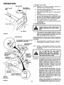
OPERATION
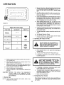
1. Stopping Your Tractor
AIR SCREEN
NOTE:
OIL FILLER
CAP/DIPSTICK
FUEL FILLER
CAP
a.
b.
c.
d.
e.
f.
REMOVE KEY WHEN LEAVING TRACTOR
PREVENT UNAUTHORIZED USE:
TO
Push clutch-brake pedal intofull "BRAKE" position.
Keep your foot on pedal (Fig. 7).
Place attachment clutch lever in "DISENGAGED"
position,
Move gearshift lever to "NEUTRAL" position.
Lift up to place parking brake in "ENGAGED" position (Fig. 10) and release pressure from clutch!
brake. Pedal should remain in "BRAKE" position.
Move throttle control to "S" (slow) position.
Turn ignition keyto"OFF"position.
to stop engine.
Never use choke
2. Preparing the Engine
FUELTANK
LEARN TO STOP YOUR TRACTOR BEFORE ATTEMPTING TO START THE ENo
GINE.
/
OiL DRAIN
a.
FIGURE 6
iGNITION KEY
ATTACHMENT CLUTCH LEVER
"ENGAGED" POSITION
This engine has been shipped filled with summer
weight oil (For cold weather operation see chart
page 16). Check engine oil level. Refer to REPAIR
AND ADJUSTMENT section (page 16).
Changing oil after the first two hours (or two mowings) will
help eliminate break-in residue which might be damaging to
your engine.
b.
Fill fuel tank (Fig. 6). Use fresh, clean, regular unleaded gasoline. Capacity is 5 quarts (4.7 litres).
"DISENGAGED"
POSITION
NOTE: FRESH, CLEAN WINTER GRADE FUEL MUST
BE USED TO INSURE GOOD COLD WEATHER
STARTING
FILL TO BOTTOM
OF GAS TANK
FILLER NECK. DO NOT OVERFILL.
WIPE OFF ANY SPILLED OiL OR FUEL.
DO NOT STORE, SPILL OR USE GASOLINE NEAR AN OPEN FLAME.
PARKING
BRAKE
HEADLIC
SWITCH
THROTTLE
CONTROLLEVER
POSITION
CAUTION:
GEARSHIFT
LEVER
TO AVOID ENGINE PROBLEMS, THE FUEL
SYSTEM SHOULD BE EMPTIED BEFORE
STORAGE FOR 30 DAYS OR LONGER.
DRAIN THE GAS TANK, START THE ENGINE AND LET iT RUN UNTIL THE FUEL
LINES AND CARBURETOR
ARE EMPTY.
USE FRESH FUEL NEXT SEASON. SEE
STORAGE
INSTRUCTIONS
FOR ADDI°
TIONAL iNFORMATION.
"CLUTCH"
POSITION
CLUTCH/BRAKE
"DRIVE"POSITION
"BRAKE"
POSiTiON
FIGURE 7
EXPERIENCE INDICATES THAT ALCOHOL
BLENDED FUELS (CALLED GASOHOL OR
USING ETHANOL OR METHANOL) CAN ATTRACT MOISTURE
WHICH
LEADS TO
SEPARATION AND FORMATION OF ACIDS
DURING STORAGE.
ACIDIC GAS CAN
DAMAGE THE FUEL SYSTEM OF ANY ENGINE WHILE IN STORAGE.
10
NEVER USE ENGINE OR CARBURETOR
CLEANER PRODUCTS iN THE FUEL TANK
OR PERMANENT DAMAGE MAY OCCUR.
OPERATION
3. StarUng the Engine
a. Move throttle control lever (Fig. 7) past "FAST" to
the "CHOKE" position.
b. FuUy depress clutch/brake pedal.
c. Turn ignition key to "START" and release key as
soon as engine starts.
CAUTION:
ff engine does not start
throttle control lever to
minutes and try again,
after
four
or
five
TROUBLESHOOTING
e.
After the e ng!ne sta_s move throttle control lever
slowly to the SLOW' position.
To start a hot engine move the throttle control lever
to a position between "FAST" and "SLOW".
LiFT LEVER
"HIGHEST"
POSiTiON
"LOWEST"
POSITION
DO NOT RUN STARTER CONTINUOUSLY
FOR MORE THAN FIFTEEN SECONDS PER
MINUTE.
d.
f.
ATTACHMENT CLUTCH
LEVER "ENGAGED"
POSiTiON
ATTACHMENT CLUTCH
LIFT LEVER
LEVER "DISENGAGED"
PLUNGER
POSITION
after four or five tries, move
FAST" position, wait a few
if the engine does not start
more tries,
see the
Chart (page 25).
READ THE "RULES FOR SAFE OPERATION" CAREFULLY BEFORE OPERATiNG YOUR MOWER.
R.H. RUNNER
DO NOT OVER LOAD TRACTOR BY
TOWING WEIGHTS GREATER THAN
150 POUNDS {68 KG).
DISCHARGE
GUARD
ALWAYS WEAR SUBSTANTIAL FOOT=
WEAR AND AVOID LOOSE FITTING
CLOTHING
THAT
COULD
GET
CAUGHT iN MOVING PARTS.
DO NOT OPERATE THE MOWER WiTHOUT EITHER THE ENTIRE GRASS
CATCHER,
ON
MOWERS
SO
EQUIPPED,
OR
THE
DEFLECTOR
SHIELD iN PLACE,
RGURE8
WHEN PARKING BRAKEIS ENGAGED,
MAKE SUREIT WILL KEEP TRACTOR
FROM MOVING.
NEVER PLACE YOUR HANDS OR FEET
IN OR UNDER ANY POWERED ATTACH=
MENT OR NEAR ANY MOVING PART
WHILE TRACTOR OR ANY POWERED
ATTACHMENT IS RUNNING.
CAUTION
TO AVOID INJURY
1.
2.
3.
Read owner's manual.
Know location and function of all controls.
Keep guards, safety shield and switches in place and
working.
4. Remove objects that can be thrown by blades.
5. Do not mow when children and others are around.
6. Never carry children or passengers.
7. Always look behind machine before backing.
8. Do not mow where machine can tip or slip.
9. if machine stops going uphill, stop blades and back
slowly down.
10. Be sure blades and engine have stopped before placing
hands or feet near the blades.
11. Remove key when leaving machine.
4. Operating Your Lawn Tractor and Mower
NOTE: THIS TRACTOR iS EQUIPPED WITH AN OPERATOR PRESENCE SENSING SWITCH. ANY ATTEMPT BY THE OPERATOR TO LEAVE THE
SEAT WITH THE ENGINE RUNNING AND THE
ATTACHMENT CLUTCH LEVER ENGAGED WILL
SHUT OFF THE ENGINE.
CAUTION: DO NOTADDADDITIONAL
WEIGHT
TO THE TRACTOR OTHER THAN THE OPTIONAL
WHEEL
WEIGHTS.
EXCESSIVE
WEIGHT MAY OVERLOAD AND DAMAGE THE
TRANSAXLE.
a.
b.
c.
11
Depress lift lever plunger and move the attachment
lift lever to the highest position. See Fig. 8.
Start the engine. (See Starting the Engine).
Move the throttle lever to mid range position. Fully
depress clutch/brake pedal Select a low (Ist or 2 nd)
gear until you become more familiar with the operation of the unit.
....
OPERATION
f
Tf
a.
Mower should be adjusted properly front to back
and side to side for good mowing performance. Refer to REPAIR AND ADJUSTMENT section (page
22).
b.
Use the runner on the R.H. side as a guide; the
blade cuts approximately an inch (2.54 cm) outside
the runner (Fig. 8).
c.
Drive so that clippings are discharged onto the area
that has been cut. Have the cut area to the right of
the machine. This will result in a more even distribution of clippings and more uniform cutting.
d.
When mowing large areas (Fig. 9), start by turning
to the right so that the clippings will discharge away
from shrubs, fences, driveways, etc. After two or
three rounds, mow in the opposite direction making
left hand turns until finished.
e.
If grass is extremely tall, it should be mowed twice.
The first time cut relatively high; the second time to
the desired height.
f.
The left hand side of mower should be used for trimming.
g,
See Speed Selection Guide.
h.
Do not mow tall, dry (brown) grass over 6 inches
(15.24 cm) tall. It is a fire hazard.
J
FIGURE 9
SPEED SELECTION GUIDE
FUNCTION
Normal
GEARSHIFT
THROTTLE
2or3
Mowing
Heavy Mowing
1 or2
6. Operating
Snow
Blade
d.
e.
f.
g.
h.
i.
2
4-5
Transport
DO NOT DRIVE UP OR DOWN HILLS
WiTH SLOPES GREATER THAN 15 °
AND DO NOT DRIVE ACROSS ANY
SLOPE. REFER TO PAGE 47.
SLOWFAST
a.
Move gearshift lever to "lst" gear before starting up
or down hills.
b:
AVOID STOPPING OR SHIFTING ON HILLS.
c.
if slowing is necessary, move throttle control lever
to slower position.
Slowly release clutch/brake pedal and proceed to
the mowing area.
Stop the unit, then select a mowing speed. (See
Speed Selection Guide, above).
LEAVE ENOUGH ROOM WHEN STOPPiNG AND STARTING
TO ALLOW
SLIGHT TRACTOR ROLL DOWNHILL
AS CLUTCH/BRAKE
PEDAL MOVES
THROUGH CLUTCH POSITION.
Move throttle lever to half throttle and slowly move
attachment clutch lever to engaged position, Fig. 8.
Slowly release clutch/brake pedal.
Move throttle lever to fast position.
Observe height of cut and readjust as desired (see
page 9).
CAUTION:
the Tractor on Hills
FAST
Snow Blowing
BEFORE YOU MOVE THE GEARSHIFT
LEVER, COME TO A COMPLETE STOP.
FAILURE TO DO SO CAN RESULT IN GEAR
BOX DAMAGE.
If stopping is absolutely necessary, push clutch/
brake pedal quickly to brake position.
e.
To restart tractor movement, make sure tractor is in
the lowest speed range ("1st" Gear) and release
clutch/brake pedal SLOWLY.
f.
Make allturns gradually.
7. Transporting
5. Mowing Tips
NOTE: TiRE CHAINS CANNOT
MOWER ATTACHED.
d.
Your Tractor
For pushing or towing your tractor, place gearshift lever
in "N" position. Do not tow or push at more than 6 MPH
(9.7 KPH).
BE USED WITH THE
12
MAINTENANCE
To keep yourtractor running
perform
necessary setvioe
ing maintenance
schedule:
WiTH EVERY
better and longer,
using the follow=
FOR
ANY ADJUSTMENTS,
TiON OR MAINTENANCE:
1. PUSH TRACTOR
CLUTCH/BRAKE
PEDAL
COMPLETELY
iNTO
"BRAKE" POSITION.
MOWING
1.
Make sure all nuts on bomtsare tight and cotter pins and
retainer springs are secure.
2.
Observe all safety precautions.
3.
Keep tractor well lubricated (refer to page 24).
4.
Make sure areas around muffler, engine and mower
deck are clean and free of debris buildup.
iNSPEC-
2. MOVE GEARSHIFT
POSiTiON,
TO "N" NEUTRAL
3. PLACE PARKING BRAKE IN "ENGAGED" POSiTiON. REMOVE FOOT
FROM PEDAL.
4. PLACE
LEVER
TION.
ATTACHMENT
CLUTCH
iN "DISENGAGED"
POSi-
5. TURN iGNiTiON
SITION.
KEY TO "OFF" PO-
6. MAKE
ABSOLUTELY
SURE THE
BLADES AND ALL MOVING PARTS
HAVE COMPLETELY STOPPED.
7. REMOVE THE iGNiTION KEY.
8. DISCONNECT
THE SPARK
PLUG
WIRE FROM THE SPARK PLUG AND
KEEP WiRE AWAY FROM THE PLUG
TO PREVENT iNJURY FROM ACCF
DENTAL STARTING. BE CAREFUL
TO AVOID TOUCHING HOT ENGINE
OR MUFFLER COMPONENTS.
RECORD
FILL IN DATES
AS YOU COMPLETE
REGULAR SERVICE
SERVICE
Change Engine Oil
Check Brake
Check Tire Pressure
Clean Air Screen
Clean Air Cleaner
Lubricate Pivot Points
Level and
Clean
and Terminals
Carburetor Ad
V-Belt Adjustment
Clean Engine Cooling Fins
Check Muffler
Replace Air Cleaner Paper Cartridge
Replace Spark Plug
i
Replace Fuel Filter
13
DATES
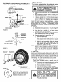
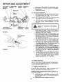
1, Brake Adju_ment
D_DA|D
"--'-"""
Th 0, octor
i.
w,.oondjo0tab
brow0
sy0tom
mounted on the right side of the transax_e (F_o 10).
_WITHPARKING
RAKE ENGAGED)
j _
NUT"A"
DI_HEST
GEAR, THEN
a.
Depress clutch_brake pedaJ and engage parking
brake.
b.
Measure distance between
and nut "A" on brake rod_
brake operating arm
c.
if distance is other than 1-1/2" (3.8t cm), k)osen
jam nut (Fig. 10) and turn nut until distance becomes 1-1/2" (3.81 cm)o Retighten jam nut against
nut "A".
Road test tractor for proper stopping distance as stated
above. Readjust if necessary, ff stopping distance is _ill
greater than 6 feet ft.8 meters) in highest gear, further
maintenance is necessary. Contact your k)caJ Sears Serv=
ice Center.
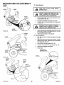
2. Tire(3are
JAM NUT
DiSC BRAKE
a.
FIGURE 1o
b.
c.
d.
Maintain tire pressure in front at 14 PSi (tKg/cm 2)
and rear tires at 10 PSi (0.7 Kg/cm2).
Keep tires free of gasoline, oil, or insect controJ
chemicals which can harm rubber.
Avoid stumps, stones, deep ruts, sharp objects and
other hazards that may cause tire damage.
Removing wheel for tire repair (Fig. 12).
1. Block up axle secureJy.
2. Remove hub cap, klip ring and washerto allow
wheel removai (rear wheel contains a square
key - Do Not Lose).
3.
Repair tire and reassemble. Align slots in rear
wheel hub and axle. insert square key. Replace washers and snap kfip ring securely in
axle groove. Replace hub cap.
NOTE: USE GREASE FiTTiNGS TO LUBRICATE FRONT
WHEELS WITH GENERAL PURPOSE GREASE.
APPLY AN ANTI-SEIZE OR GOOD GENERAL
PURPOSE GREASE TO LUBRICATE REAR AXLES.
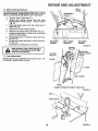
3. Btade Care
For best results mower blades must be kept sharp. The
blades can be sharpened with a few strokes of a file, or on a
grinding wheel We suggest they be sharpened after every
25 hours of mowing. Do not attempt to sharpen while on
mower. Jtyou mow in sandy _i_ check the blades a_ter each
two redwings. The sand wears the blades away rapidBy.
a. Blnde Replacement
Raise mower to h_ghest position to pe_it access to
bmades.
1. Remove the hex head belt, Iockwasher and flat
washer (Hg. 11 ) (turn counterck)ckwise).
2. Remove and discard oldbladed
FIGURE 11
HUBCAP
SQUARE KEY
(REARTIRE ONLY)
3.
4.
Clean top and bottom of mower housing.
Install new blade with SHARP EDGE DOWN
and secure with flat washer, k_kwasher and
hex head belt. TIGHTEN SECURELY.
ALWAYS
TREATED
A GRADE 5 HEAT TREATED
BOLT CAN BE IDENTIFIED BY
THREE LINES ON THE BOLT
HEAD ASSHOWN ATLEFTo
t4
USE
GRADE
BOLTS
TO
5
HEAT
ATTACH
CHECK
_NBLADES
OCCASIONBLADES.BOLTS
DO NOT
USE PLATED
BOLTS.
ALLY TO MAKE SURE BOLTS ARE
TIGHT, TORQUE
BOLTS TO 30_5
FT.-.4_BS (41--47 Nm).
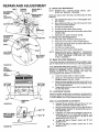
c.
proper balance before reinstaliation on mower. An
unbalanced or bent blade will cause excessive vibration when running, and eventual damage to
mower or engine. Replace bent or damaqed blades.
To check blade balance, drive a nail into a beam or
waft. Leave about one inch (2.54 cm) of the straight
nai! exposed. Place center hole of clean blade
over the head of the nail (Fig. 13). NOTE: CENTER THE HOLE OF BLADE ON NAIL. IF BLADE
iS PROPERLY BALANCED, BLADE SHOULD
REMAIN iN POSiTiON SHOWN iN FIG. 13. IF
EITHER END OF THE BLADE MOVES DOWNWARD, BLADE iS NOT BALANCED. SHARPEN
THE HEAVY END UNTIL BLADE IS BALANCED.
4. t_ttery
Care
CHECK BATTERY
a.
b.
c.
d.
e.
Battery acid sotution level in each battery cell should
be even with bottoms of vent tubes in cells (Fig. 14).
Add ONLY distilled or iron free water if necessary.
NOTE: DO NOT OVERFILL.
Keep battery and terminals clean.
Keep battery bolts tight.
Keep vent caps tight and small vent holes in caps
open.
Recharge with auto battery charger.
NOTE: OVERCHARGING
LIFE°
WILL
SHORTEN
FIGURE 13
BATTERY
CUTAWA_ YVlE_
FC W
_/
BATTERY
gH/L V L
CLEAN BATTERY AND TERMINALS
Corrosion and dirt on the battery and terminals cause the
battery to "leak" power and hinders the operation of the
charger.
....
|
|
_TTERIES
GENERATE
FIGURE 14
,AJk FLAMEAND SMOKINGMATER!$LS
,mwm_
WEAR
EYE
PROTECTION
WHEN
a.
b.
Remove terminal guard.
Disconnect BLACK battery cable, then RED battery
cabte, and remove battery from tractor.
c.
Wash batte_ with four tablespoons (60grams) of
baking soda in one gallon (3.8 litres) of wa_er.
NOTE: BE CAREFULL NOT TO GET THE SODA
SOLUTION INTO THE CELLS.
d.
R_nse the battery with plain water, dry and reinstall
on tractor.
Clean terminals and battery cable ends with wire
brush until bdght.
Rep_aco batterycables, connecting RED batterycab_eto positive terminal first, then BLACK battery cabte to negative terminal Coat terminal connections
with grease after installation of cables.
Replace terminal guard.
e.
f°
g.
BATTERY
S. Change Engine Oil
The best time to change engine oil is at the end of a day's
operation when all dirt and foreign materials are suspenDeD
in the hot oil
Capacity is 1-1/2 quarts (1.4 litres). NOTE: DO NOT
OVERFILL Dipstick assembiy rnust be securely tightened
into tube at all times when engine is operating.
15
....
ANol| f TM hlT
.................
v v,_,,--=w,
AiR
SCREEN
FUEL CAP
.......
oil
drain
plug
todrain
e ine
oil
h,m _-b.
OiL FILLER
CAP/DIPST_CK
plug securely before fitling with fresh oil
Add oi! through the oil filler cap/dipstick (F_g. 15).
RECOMMENDED SAE VISCOSaTY GRADES
°F °20 °
°C °29 °
0°
-18 °
32 °
0_
60 °
16 °
80 °
27 °
100 °
38 °
6. Check Engine Oil Level
NOTE: DO NOT CHECK ENGINE OiL LEVEL WITH ENGINE RUNNING
Severaa minutes after stopping engine, check engine oil
level with tractor on level ground. Wipe dipstP.,k (Fig. 15)
clean, screw it down tighf for a few seconds, remove and
read oil level. If necessary, add oil until "FULL" mark is
reached. (See chart above). NOTE: DO NOT OVERFILL
/
/
OiL DRAIN PLUG
Clean Air Cleaner EBement (Fig. 16)
a. Remove two cover knobs and remove air cleaner
cover.
COVER
b.
c.
7_
FIGURE 15
COVER
FIBER
WASHER
d,
e_
NOTE:
3E
PLATE
NUTS
Remove two nuts from top of cartridge.
Remove cartridge and clean air cleaner body carefully to prevent dirt from entering carburetor.
Clean cartridge by gently tapping on flat surface, if
very dirty, reptace cartridge.
ReassembJe air cleaner.
NUTS HOLDING AiR CLEANER CARTRIDGE
MUST BE iNSTALLED WITH FIBER WASHERS
DOWN ON CARTRIDGE PLATE TO PREVENT
DIRT
FROM
ENTERING
CARBURETOR.
TIGHTEN NUTS BY HAND. OVER TIGHTENING
COULD COLLAPSE CARTRIDGE.
NOTE: NEVER RUN ENGINE WITH AIR CLEANER REMOVED.
CARTRIDGE
8, Clean Air Screen and Engine Cooling Fins
AmRCLEANER
BASE
J
,4_L_NENUSING
AIR.
FIGURE 16
Air screen
and chaff
Clean with
dried gum
COMPRESSED
.........
and cooting fins {Fig. 17) must be kept free of dirt
to prevent engine damage from overheating.
a wire brush or compressed air to remove dirt and
fibers.
a.
b.
c.
IMPORTANT:
Remove four bolts from bbwer housing.
Remove screws from starter housing.
Pull oil fiHer/dipst_ck out of crankcase Jfclearance is
required. Cover opening to prevent entry of dirt.
do Puflbbwer housing up and away from starter.
TO AVOID DAMAGE TO THE STARTING
SYSTEM, USE SAE 5W30 OIL WHEN
THE TEMPERATURE
FALLS BELOW
32°F (0°C).
NOTE: LEAVE AIR CLEANER iN PLACE TO PREVENT
DEBRIS FROM GETTING iNTO CARBURETOR.
e.
RECO_,{MENDED SAE VISCOS_TY GRADES
f.
Determine temperature range expected before next oit
change. M oil must meet A. P.L service classif k:atbn SD, SE
or SF.
16
Use compressed
air or stiff bristte brush
thoroughly c_ean engine fins.
To reassemble, reverse above procedure.
to
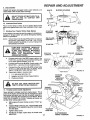
RE PAiR AN DADJ USTM ENT
$. Cit_ck Muffter
inspect and reptace damaged muffler and/or deflector as it
¢outd create a fire hazard and/or damage,
BOLTS
BLOWER HOUSING
10. Lubricate Pivot Points
Place several drops of SAE 30 oil at points where metal
parts move against each ether. See Lubrication Chart, page
24.
AiR SCREEN
11o Starting Your Tractor With a Weak Battery
Ityou r battery is toe weak to start the engine, itshould be recharged, if "jumper cables" are used for emergency starting,
follow this procedure:
NOTE: YOUR TRACTOR IS EQUIPPED WiTH A 12 VOLT
NEGATIVE GROUNDED SYSTEM. THE OTHER
VEHICLE MUST ALSO BE A 12 VOLT NEGATIVE
GROUNDED SYSTEM.
LEAD-ACiD
BATTERIES
GENERATE
EXPLOSIVE GASES. KEEP SPARKS,
FLAME AND SMOKING
MATERIALS
AWAY FROM BATTERIES.
ALWAYS
WEAR
EYE
PROTECTION
WHEN
AROUND BATTERIES.
HOUSING
_--_
DIPSTIC
STARTER
_.
ENGINE
COOLING
FiNS
FIGURE 17
POSITIVE
TI
WASHER
WASHER
NEGATIVE
VIINAL
HEX BOLTS
a.
b°
c.
d.
Connect each end of the RED jumper cable to the
POSITIVE(+) terminals of each battery (taking care
not to short against chassis). (Fig. 18).
Connect one end of the BLACK ju mper cable to the
NEGATIVE (-) terminal of tully charged battery.
POSITIVE
CABLE
(RED)
Connect the ether end of the BLACK jumpercable
to the LH. side panel bolt (Fig. 19) NOTE: KEEP
AWAY FROM GAS TANK AND BAT[ERY.
Disconnect cables in reverse order:
1.
2.
3.
12o Thrott_
-.
, NEGATIVE
CABLE
(BLACK)
HE;< NUTS /
FIGURE 18
LH. side panel belt (Fig. 19)
Negative terminal of fully charged battery
Positive terminals
GEAR
SHIFT
LEVER
C_ntrol Cable Adjustment
Never attempt to change maximum engine speed. This Is
preset at the factory and should only be changed by a qualified service technician who has the necessary equipment.
CAUTION: BEFOREANY ENGINE ADJUSTMENT, MAKE
SURE AiR CLEANER iS CLEAN. Remove air cleaner assembly while making adjustments.
a.
W°_thengine off, place throttle centre! in "FAST" position.
b.
Loosen cla.m_, screw (Fig. 20). Adjust throttle cable
until holes A are aligned in governor control plate
and sideplate.
c.
d.
T=ghten damp screw.
if holes do r_t align, repeat steps in throttle cable
adjustment.
17
CLUTCH/BRAKE
"DRIVE" POSITION
FIGURE 19
REPAIRANDADJUSTMENT
(DLE STOP
b.
c.
Loosen clamp screw (Fig. 20). Adjust throttle cable
until holes "A" are aligned in governor control ptate
and side plate.
Tighten damp screw.
!3. Catbureter Adjustment
a. With engine offtum high speed mixture screwclock-
NOTE: THE SCREW SEAT MAY BE DAMAGED
TURNING iT TOO FAR CLOCKWISE
b.
PLATE
GOVERNOR
CONTROL
A
SLIDE
PLATE
BY
Turn idle mixture screw clockwise closing finger
tight only, and turn counterclockwise 1-1/2 turns
(F O. 20).
REFERpAGE
11.TO"STARTING
THE ENGINE"
FIGURE 20
/
d.
.G30" FEELER
GAUGE
e.
f,
SPARK PLUG
FIGURE 21
With throttle control lever in "FAST" position, turn
high speed mixture screw counterclockwise until
eng=ne runs "rough" and then turn clockwise until
engine begins to miss. Turn screw to a point midway between these positions.
With throttle control lever in "SLOW" position, hold
throttie lever so that idle stop screw is against car,buretor, tum idle mixture screw counterclockwise
unti! engine runs" rough" and then turn clockwise
until engine begins to die. Turn idle mixture _rew to
a point midway between these positions.
With throttle control lever in "SLOW" position engine should idle at 1750 RPM. ff engine idles too
slow, push throttle control lever above idle and turn
idle speed screw one turn clockwise. Set throttle
control lever at "SLOW'.
Repeat until satisfactory
idle is attained.
idle and turn idle speed screw erie turn counterclockwise. Set throttle controt lever at "SLOW:
Repeat until satisfactory idle is attained,
!4. Replace Spark Plug
Replace spark plug at the beginning of each mowing season
or every 100 hours, whichever comes first. Gap shoutd be
set a 0,030 inch (0,762 mm) (Fig. 2t).
15. Replace In-l_ne Fue_ F_tter
BE SURE THERE ARE NO FUEL LiNE LEAKS AND THAT
HOSE CLAMPS ARE PROPERLY iNSTALLED.
ff fuel tilter is c_ged, obstructing fuel flow to carburetor, replacement is required.
a. W"h
s ions
e.thor
ioo"wero
b.
18
fi_ter (F_g. 20).
Place new fue_ filter in position in fue_ _ine.
REPAIR AND ADJUSTMENT
16. _n
Drive _k
BELT
GUIDE
Removal
The tractor drive her may be repaacedwithout t_ls. Park the
tractcr on level area. Engage parking brake. NOTE: A BELT
INSTALLATION DECAL IS UNDER LEFT FOOTREST.
TRANSAXLE
a.
b.
Ren_ve mower. (See page 21).
Remove two retainer springs from belt guide
bracket below transaxle p_JHey. Remove bracket
(Fig. 22).
c. Swing beat guides away from bett, toward rear of
tractor (Fig. 22),
d. Rofl belt overtop of transaxle pulley.
e. Roll ben over engine pulley and off idler (Fig, 23).
f.
Release parking brake. Pull belt as far as possible
over top of clutch polEey.
g. Reset parking brake. Pull be_t over top of clutch pulley (Fig. 23).
h. Pull ben out through shift gate to remove from tracfor (Fig. 24).
i. Instafl belt by reversing above procedure,
BELT GUIDE
BRACKET
RETAINER
SPRING
FIGURE 22
ENGBNE
PULLEY
BELT
DECAL
17. Fuse Replacement
Rep|ace with 30 amp automotive-type
fuse holder is Bocated under the dash.
plug-in
fuse, The
L.H. SiDE
BELT GUIDE
REAR
_
VIEWED FROM BOTTOM OF TRACTOR
FIGURE 23
BELT
SHIFT GATE
1g
FIGURE 24
RE PAIR,AND.ADJUSTMENT
18o Hood Remov_J
GRASP
HERE
HOOD
DASH
\
HOOD
SPRING
a.
Grasp hood at edge next to dash and open hood to
fu_i up position (Fig. 25).
b.
Disconnect headlight connection
(Fig. 28).
Co Carefully remove hood springs from hinge brackets (Fig, 25).
FIGURE 25
ANO
HINGE
BRACKET
d.
_3P
HERE
INSTALL O,.
Lowerhood halfway and grasp atthe bottomofthe
grill and at the upper hood edge (Fig. 26). Lift hood.
up, out and away from tractor.
e. Place hood carefully on the ground.
19. Hood installation
a.
Pick hood up at top of grill and upper hood edge
(Fig. 27).
b.
Align hood pivot rod with hinge brackets. Rotate
hood half way down, slide pivot rod in and down
into hinge slots (Fig. 27).
c.
Open hood to full up position (Fig. 25).
d.
Carefully reinstafl hood hinge springs (Fig. 25)°
e.
f,
Reconnect headlight connection.
Close hood.
HEADLIGHT
GRASP
HERE
RGURE26
G
HERE
HOOD_
HOOD
PIVOT
ROD
HINGE
BRACKET
FIGURE 27
20
FIGURE 28
....
REPAiR AND A DJU STM
2o. Mower R_rnovai
a.
b.
c.
d.
e.
f.
ATTACHMENT
CLUTCH LEVER
"DISENGAGED"
POSITION
Remove mower belt per instructions under "Mower
Drive Belt Removal" through step (c).
Remove retainer spring from clutch red; pull clutch
rod out of clutch bracket. (Fig. 29)
Pul! retainer springs out of rear suspension trunnions. Remove rear suspension trunnions from lift
brackets (Fig. 29).
Pull retainer spring out of rear hinge pin. Remove
rear hinge pin. (Fig. 29).
Pull retainer spring out of front hinge pin. Remove
front hinge pin (Fig. 29).
Use liftleverto raise suspension arms. Slide mower
out from under tractor.
LIFT LEVER
PLUNGER
LEVER
"HIGHEST"
POSITION
LIFT LEVER
"LOWEST"
NOTE: IF AN ATTACHMENT OTHER THAN THE MOWER
DECK IS TO BE MOUNTED ON THE TRACTOR,
THE L.H. AND R.H. SUSPENSION ARMS (FIG.
29) SHOULD BE REMOVED FROM TRACTOR.
21. Mower Installation
Your Mower installs without the use of tools. Raise attachmerit lift lever (Fig. 30) to its highest position_
a.
b.
c.
d.
e.
f.
g.
h.
Slide mower under tractor discharge guard to R.H.
side.
Install front hinge pin through axle and parallel link
(Fig. 32). Secure with retainer spring.
Install rear hinge pin through mower lift brackets
and parallel link (Fig. 32). Secure with retainer
spring.
Install clutch rod in clutch lever (Fig. 32).
FIGURE 30
Move attachment lift lever (Fig. 30) forward to lower
suspension
arms. Slide trunnlons through lift
bracket holes and secure with retainer springs (Fig.
29).
Roll belt over engine pulley. Make sure belt is inside
belt guides (Fig. 32). See belt drive schematic decal
on mower housing
Use attachment lift lever (Fig. 30) to raise mower.
Push lift lever plunger down and pesition
attachment lift lever to desired cutting height (Fig.
31). Release lift lever plunger.
RETAINER
SPRING
FIGURE 29
o
UFT
_RACKET
Q_
RGURE 31
RETAINER
SPRING
R.H,
SUSPENTION
ARM
CLUTCH ROD
REAR
SUSPENSION
TRUNNIONS
0
ENGINE
PULLEY
RETAINER
SPRINGS
CLUTCH
BELT
GUIDES
RETAINER
SPRINGS
MOWER
LIFT
BRACKETS
HINGE
PINS
21
PARALLEL
LINK
FRONT
AXLE
REAR
HINGE
PiN
FRONT
HINGE
PIN
FIGURE 32
22. Mower Drive Belt Removal
NOTE: MOWER BELT INSTALLAT!ON
ATED ON MOWER HOUSING.
DECAL
REPLACE ONLY WITH THE BELTS SPECiFiED
MANUAL.
LOCIN THiS
a.
COTTER
EXTENSION
f_
SPRING
BRAKE,
ROD
COTTER PiN
Place attachment clutch lever in "Disengaged" position (Fig.30).
b. Move Attachment liftlever (Fig. 30) forward to lower
mower to its lowest position.
c. Roll belt off engine pultey.
d. Pull belt off both mower deck pulleys.
e. Spring belt guide away from idler pulley and pull belt
off idler pulley.
fo Slide belt from under extension spring.
23. Mower Drive Belt Replacement
a. Slide belt under extension spring (Fig. 33).
b. Place belt on rear side of both mandrel pulleys.
c.
d.
e.
LH. PIVOT
BRACKET
j
R.H. PIVOT
BRACKET
Spdr_j idler belt guide down and place belt around
rear s_de of idler pulley.
Roll belt over engine pulley.
Make sure belt is inside all belt guides.
NOTE: WHEN INSTALLING A NEW BELT, EXTENSION
SPRING MUST BE RETURNED TO LOWER END
OF SLOT (ORIGINAL POSITION) ON
ROCK
SHAFT ASSEMBLY.
24. Mower Drive Belt Adjustment
Your tractor has been manufactured with the ability to readjust the mower belt drive to provide you with longer belt life.
FIGURE 33
If the attachment clutch lever travels 4-1/2" (! 1.43 cm) up
the slot in the dash before spring resistance is evident, adjustment is necessary. NOTE: CHECK FOR PROPER
SPRING TENSION WtTH THE ENGINE OFF AND THE
LIFT LEVER IN THE HIGHEST POSITION.
LiFT
LEVER
LiFT
LEVER
a.
Lower the mower deck for easier access.
b.
Using (2) 7/16"wrenches, remove the bolt, nut & DShaped washers (Fig. 33 - inset).
Move extension spring from lower end of slot to upper end in rock shaft assembly and install belt, nut &
the D-Shaped washers.
Tighten bolt and nut to secure the D-shaped washers (flat side down).
c.
BOTTOM
OF CURL
BOTTOM
OF CURL
d.
25. Level Mower Housing
Adjust the mower while tractor is parked on level ground or
driveway. Make sure tire pressure _scorrect. If tires are over
or under inflated, you will not properly adjust your mower.
SiDE-TO-SIDE
LiNE
FIGURE 34
"_aL_/NUT
SIDE TO SIDE_
a.
Depress lift lever plunger and use lift lever to raise
mower to maximum cutting height (Fig. 31).
b.
Measure height from bottom of curt to ground line at
front of mower. Distance "A" should be the same on
both sides (Fig. 34).
If distance "A" needs to be changed, snap out access hole cover on LH. side above footrest. Use
! 1/!6" wrench on nuts "B" and "C" at side-to-side
adjustment trunnion (Fig. 35).
To raise left side of mower, loosen nut "B" and
tighten nut "C".
To lower left side of mower, loosen nut "C" and
tighten nut "B".
"C"
LJ
c.
/
d.
e.
FIGURE 35
22
MOWER ADJUSTMENT
NOTE:ONEROTATIONOF ADJUSTMENT
NUTSIS
EQUIVALENT
TO APPROXIMATELY
3/16"(4.75
ram)HEIGHTCHANGE.
f. Besureal!nutsaresecurelytightened.
g. Replace
cover.
FRONT-TO-REAR
MOWER
REAR
SUSPENSION
ARM
\
ADJUSTMENT
a.
To obtain the best cutting resu Its, you r mower housing should be adjusted so the front and rear flange
distance "D" (Fig. 36) is 1/2" (1.27 cm) lower in front
when the mower is positioned in the highest cutting
position.
NOTE: MEASURE DISTANCE "D" FROM GROUND LINE
TO BOTTOM OF CURL ON RIGHT REAR
FLANGE AND COMPARE TO DISTANCE"D" AT
BOTTOM OF CURL ON RIGHT FRONT FLANGE.
BOTTOM
OF CURL
D_EAR
--_
GROUND
LiNE
SUSPENSION
TRUNNION
b.
To raise rear of mower, loosen nut "E" on both rear
suspension arms. Screw both nuts "F" up EQUAL
NUMBER OF TURNS (Fig. 37).
c. When distance "D" is 1/2" (1.27 cm) lower at front
than rear tighten nuts "E".
d. To lower rear of mower, loosen nut "F" on both rear
suspension arms an EQUAL NUMBER OF TURNS
(Fig. 37).
e. When distance "D" is 1/2" (1.27 cm) lower at front
than rear, retighten nuts "E".
NOTE: WHEN ADJUSTING REAR SUSPENSION TRUNNIONS, ALWAYS ADJUST BOTH EQUALLY SO
MOWER WILL STAY LEVEL.
FIGURE
REAR NUT "E"
SUSPENSION \
TRUNNION
___
\
.... _,
36
REAR
SUSPENSION
ARM
LIFT
_
BRACKET
26. Storage
Remove mower from tractor for winter storage. When
mower is to be stored for a period of time, clean it thoroughly,
remove all dirt, grease, leaves, etc.Give blades and underside of housing a good coat of grease or rust preventative.
Store in a clean dry area.
A. Fuel System
FIGURE 37
it is important to prevent gum deposits from forming in essential fuel system parts such as the carburetor, fuel filter,
fuel hose, or tank during storage. Also, experience indicates
that alcohol blended fuels (called gasohol or using ethanol or
methanol) can attract moisture which leads to separation
and formation of acids during storage. Acidic gas can damage the fuel system of an engine while in storage. To avoid
engine problems, the fuel system should be emptied before
storage of 30 days or longer.
D. Battery
LEAD-ACID
BATTERIES
GENERATE
FLAME AND SMOKING
MATERIALS
EXPLOSIVE
KEEP SPARKS,
AWAY FROMGASES.
BATTERIES.
ALWAYS
WEAR
EYE
PROTECTION
WHEN
AROUND BATTERIES.
B. Engine Oil
Drain (with engine warm) and replace with clean engine oil,
(See chart page 16).
1.
C. Cylinder
1. Remove spark plug.
2. Pour one ounce (29.5 ml) of oil through spark
plug hole in to cylinder
3,
Turn ignition key to "START' position for a few
seconds to distribute oil.
4. Replace with new spark plug.
2.
3.
4.
Prior to storage, clean terminals and top of
battery.
Disconnect
BLACK
battery
cable from
negative side of battery.
Disconnect RED battery cable from positive
side of battery.
Position cables down and away from battery.
E. General Cleaning
Clean engine, battery, seat, finish, etc. of all foreign matter.
23
LUBRICATION
Q
CHART
FRONT WHEEL Q
BEARING
FRONT
BEARING
!
I
II
,.L
Q
ENGINE
MOWER CLUTCH
PIVOT Q
Q
SAE 30 MOTOR OIL
Q
GENERAL PURPOSE GREASE
Q
REFER TO PAGE 16 FOR
ENGINE OIL SPECIFICATIONS
24
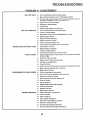
TROUBLESHOOTING
PROBLEM
CAUSE/REMEDY
WiLL NOT START
Push Clutch/Brake
Pedal into Brake position
Move Attachment Clutch Lever to "Disengaged"
position
Fii{ Tank with Gasoline. Check Fuel Line and Carburetor
necessary). Replace Fuel Fiitero Use Fresh Fuel
._
Check Fuse for fault and replace
,_
Recharge or replace Battery
(clean if
Check Wiring
_"
WiLL NOT TURN OVER
Replace Spark Plug(s) and adjust gap
Push Clutch/Brake Pedal into brake position
Charge or replace Battery
Move Mower Clutch Lever to "DISENGAGED"
position
Replace ignition Switch
=_
Replace interlock Switch(es)
_"
Replace Solenoid or Starter
=r Check for fault and replace Fuse
=_" Check at[ Wire Connections and "Ground" Points
ENGINE CLICKS BUT WON'T START
Clean Battery Terminals
Replace Starter or Solenoid
Charge or Replace Battery
,e- Check Wire Connections and "Ground" Points
HARD TO START
,_
Place Throttle Control in "FAST" position and run starter several times
to clear out gas
Remove Air Filter and clean
Replace Spark Plug(s) and adjust gap
Recharge or replace Battery
_"
_-
Cheek the Wiring
Drain Fuel Tank and Carburetor. Use Fresh Fuel. Replace Fuel Filter
,r
Make necessary adjustments to Carburetor
Major Engine Overhaul
ENGINE MISSES OR LACKS POWER
Shift to a lower gear or reduce load
=r
Drain Gas Tank and Carburetor. Use Fresh Fuel
Remove and clean Air Cleaner
Make necessary Carburetor adjustments
_"
Clean Air Screen
=_
Add or change oil
_"
Replace Spark Plug(s) and adjust gap
Check for loose wires
_"
Replace Fuel Filter
Major Engine Overhaul
ENGINE OVERHEATS ,r
Shift to lower gear or reduce toad
.=P Clean Air Screen
_"
Add or change oil
m-
Clean Engine Cooling Fins
="
Remove and clean Muffler or replace
Remove and clean Air Filter
_"
Use fresh fuel and adjust Carburetor
J-
Drain and replace oil for proper temperature
25
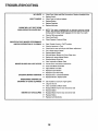
TROUBLESHOOTING
......
NO LIGHTS
WON'T CHARGE
_
Check Fuse, Switch and Wire Connections. Replace Headlight Bulbs
m-
Replace Switch
_
Check Fuse for fault and replace
_"
Replace Battery
_r
Replace Regulator
t1"
Replace Alternator
ENGINE WiLL NOT SHUT DOWN
WHEN OPERATOR
LEAVES SEAT
NOTE: This tractor is equipped with an operator presence sensing
system. Any attempt by the operator to leave the seat with the engine
running and the mower clutch engaged will shut down the engine.
m_- Check all Wire connections
UNSATISFACTORY
,_
Check Seat Switch
_-
Check Operator Presence Relay
6a=
Place Throttle Control in "FAST" position
MOWER PERFORMANCE
UNEVEN DiSTRiBUTION
OF CLIPPINGS
Check air pressure in Tires
Check front-to-rear and side-to-side
Mower adjustment
Use a slower ground speed
Replace Mower Blades
Reinstall Mower Blades with Sharp Edge down
Replace with proper Mower Blades
Readjust Mower Drive Belt
Clean underside of Mower Deck
MOWER BLADES WiLL NOT ROTATE
Correct Clutch mechanism interference
InstaEi new Mower Drive Belt
Adjust Mower Drive Belt
Replace frozen Mandrel
Replace frozen idler Pulley
EXCESSIVE
MOWER VIBRATION
m-
Replace bent or unbalanced Blades
Replace Mandrel. Replace Deck
WiNDROWING
STRIPPING OR
DROPPING OF GRASS CLIPPINGS
,r
Set Throttle for maximum engine speed
_P
Let grass dry out
Clean underside of Mower Deck
Readjust Mower front-to-rear and side-to-side
_P
UNEVEN CUT OR SCALPING
Replace Blades
Readjust Mower front-to-rear and side-to-side
Replace Blades
Replace bent Mandrel(s)
26
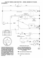
12 HP 38" RiDiNG LAWN TRACTOR--
MODEL NUMBER
917-2545201 ...........................
SCHEMATIC .....................................................................................................................
12V
ollllo
_
BLACK
RED
INTERLOCKSWITCHES
ATTMENT CLUTCH
j
I
(CLUTCH
OFF)WHFE
WHFE
I
CLUTCH/BRAKE
(PEDALUP)
1
i
I
I
I
SOLENOID
SEAT
SWITCH
(NOT OCCUPIED)
FUSE
?___)
RED
B
IGNITION
SWFr_U
30 AMP
UNIT
IGNITION
_
P
_
0-I
SPARKPLUG
BLACK
L
b
IGNITIONSWITCH
POSITION
CIRCUIT
oFF
_G
DDDE
CHARGING
RED
ON
B-L
START
B-S
COIL
20VOLTS AC (MIN}
3 AMPS DC
AT 3600 RPM,BATTERY IN LINE
ORANGE
_.
WHITE
AC COIL
u
BROWN
B_CKtP
LIGHT SWITCH
_0...._
0
_
WmRING INSULATED
YOUR TRACTOR IS EQUIPPED WITH
A SPECIAL ALTERNATOR SYSTEM,
THE LIGHTS ARE NOT CON NECTED
TO TH E BATTERY, BUT HAVE THEIR
OWN ELECTRICAL SOURCE.
BECAUSE OF THIS, THE BRIGHTNESS
OF TH E LIGHTS WILL CHANGE WITH
THE ENGINE SPEED,
AT IDLE
SPEED, THE LIGHTS WILL DIM. AS
THE ENGINE IS SPEEDED UP, THE
LIGHTS
WILL BECOME
THEIR
BRIGHTEST.
CLIPS
NOTE: IF WiRiNG INSULATED CLIPS
OR CABLE TIES WERE REMOVED FOR
SERVICING OF UNIT, THEY SHOULD BE
REPLACED TO PROPERLY SECURE
YOUR WiRiNG.
-_
NON-REMOVABLE
REMOVABLE
27
HEADLIGHT
HEADLIGHT
BLACK
CONNECTIONS
CONNECTIONS
CHASSIS
GROUND
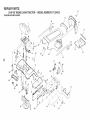
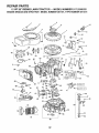
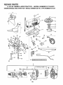
REPAIR PARTS
12 HP 38" RiDiNG
LAWN TRACTOR
- - MODEL NUMBER
917.254520
ELECTRICAL
D
26
32
98
C
32
33
30
J
\
2
32
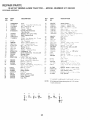
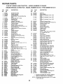
REPAIR PARTS
12 HP 38 °° RIDING
LAWN TRACTOR
- - MODEL NUMBER
917.254520
ELECTRICAL
KEY
NO.
1
2
3
4
5
6
PART
NO.
DESCRiPTiON
KEY
NO
PART
NO
DESCRIPTION
7662J
124108X
! 24904X
t093!0x
1107!2X
! 04445X
Butb, Light
Harness,
Light Socket
Harness,
Wiring
Key, Mo{ded
Switch,
Light
Switch.
Interlock
28
72240460
Bolt - Rd. Hd. Sq. Nk.
7
8
9
!0
11
! 2
13
7603J
109596X
STD365402
108824X
STD55!!25
73350400
74780408
Tray, Battery
Clamp, Hose
* Switch,
Ignit_on
Fuse, 30 Amp
*Washer,
Lock. 1/4
Nut, Hex Jam 1/4 - 20
Bolt, Hex, I/4 - 20 x 1/2
14
15
16
17
18
t 9
20
2!
STD54t425
4799J
11050400
719J
5114J
! 08553X
4207J
74760412
* Nut, Keps 1/4 - 20
Cable Assembly
Washer
Lock, Ext, Tooth,
Cover, Termina!
Cable, Battery
Switch, Interlock
Cable, Battery
Bolt, Hex, 1/4
20 × 3/4
22
23
STD551025
STD541025
° Washer
9/32 x 5/8
*Nut,
Hex I/4-20
24
25
121265X
102476X
26
27
123198X
STD55t 125
x I6
!/4
- 20 x
7-1/2
29
109081
30
! 09787X
X
Solenoid
Bezeg - Ignition
31
32
109788X
7t 92J
Nut, ignition
Cable Tie
33
105687X
Tube,
34
121305X
Switch,
35
36
STD601005
74641008
P_astic
Plunger
* Screw,Tap
Hex Hd. #10 x 24 UNC
Screw - S_otted Pan Hd No. t0-32
Gr
5
1/4
37
73951000
Nut
38
39
40
417 IR
121264X
11 ! 50400
Clip
insu!ated
Battery
Caps Set
Lockwasher
I !4 hternal
Keps
No,
10-32
× !/2
....
---
101539X
126718X
Sheet, {nstructbn, Tractor, 15 ° - English
Owner's Manual
Tooth
Ga.
Battery, 12 V. 30 Amp
TerminaI
Guard
Wing Nut !/4
_ Washer,
Lock
20
Hvy Hetical
x
1/2
NOTE:
AH component dimensions
1 inch = 25,4 ram.
Spring
"STANDARD
A
_}
B
12
C
!3
O16
D
36
35
given in U,S. inches,
HARDWAREs-PURCHASE
LOCALLY
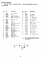
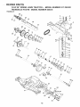
REPAIR PARTS
12 HP 38" RtDING LAWN TRACTOR
CHASSIS
AND
- - MODEL NUMBER
4O
917.254520
ENCLOSURES
55
6O
,27
,28
6t
L
38
29
D
3O
35
A
5t
59
57
53
G
/
39
A
F
F
A
31
33
13
!5
A
37
36
REPAtR PARTS
12 NP 38" RID!NG LAWN TRACTOR
=- MODEL
NUMBER
9t7.254520
CHASSIS AND ENCLOSURES
PART
NO.
DESCRIPTION
1
2
t 24497)(
17490612
3
17490616
4
! 055 ! 3X
Seat
Screw, He× Washer Thd
3/816 x 3/4
Screw. Hex Washer Thd
3/816 × !
Bracket-P_vot. Seat
5
KEY
NO.
105529X
Bolt,
6
7
8
9
tO
11
12
73680500
124181X
109872X
STD523707
17030808
73680600
!7490608
Nut
13
14
15
6
17
19
20
21
22
24
27
28
29
30
3!
32
33
34
tO9873X
STD512505
105476X
105475X
STD533707
STD551125
STD523710
19131312
124029X
19131210
124491X
108631 X
! 22933X
124027X
t 23665X
124025X
121248x
STD54!437
Shou!der,
5/I
Crownlock
Spring,
6
Ro!l
RoH_ng
18
KEY
NO.
PART
NO.
35
36
37
38
39
40
41
124479X
124355X
121306X
124294X
125880X
t24492X
4900J
Washer, Black, Nylon
42
105809X
43
109199X
44
19132012
45
46
47
48
49
50
51
52
12144OX
121441x
2751R
19131614
72170410
t23976X
121251X
12!250X
Decal, Chassis, 5 Speed, 38"
Decal, V Belt Ground Drive
Washer 13/32 × 11/4 x 12 Ga.
Guide Belt, Lower, Eng Pulley, LH.
Guide Be!t, Lower, Eng. Pulley. RH.
C_p
Washer 13/32 x l x 14 Ga
Bok, RdHd 1/4 x 20 x 1-!/4
Nut, Hex, Lg., FIange, Loc. I/420
53
54
! 2 ! 249X
121246X
Spacer,
Bracket
55
56
57
58
59
60
61
62
63
64
65
66
t24489X
124490X
123913X
t23914X
! 24040X
123915X
105037X
! 2! ! 44X
STD525010
1917t 9! 2
! 06974X
750211
Decal Std#e Hood LH.
Decal Strpe Hood R.H.
Bracket, Pivot, R.H.
Bracket, Pivot, L.H.
Spring, Extensbn
Grill
Foam, Stnp !8"
Bok, ShouMer
Bo_t, Fin Hex I/2 - 13 UNCx ! Gr. 5
Washer 17_32 x 1-3/!6 x 12 Ga.
Decal, Caution
Decal, USA
5/1618
Seat
Fender
* Bo_t, Fin Hex 3/8 x I6 UNC × 3/4
Screw, Spidedock Hex #8 x 1/2 AB
Nut, Crowntock 38"16
Screw, Hex Washer [hd Roll 3/8
16 x 1/2
Bracket. Fender
* Bok, Fin Hex 1/4 - 20 UNC x 1_
Footrest,
Footrest,
L H
R H
, Bolt, RdHdSqNk 3/8 _ 16 UNC x 3/4
° Washer, Lock, Hvy Helical Spring
* Bo!t, Fin Hex 3/8 x 16 UNC x 1
Washer 13/32 x 13/16 x !2 Ga.
Lens Assembly
Washer 13/32 x 3/4 x 10 Ga
Decal, 12 HP
Decal, :_
Rive{, Ratchet, Nylon
Shield, Hood, Heat
Deflector, Heat
Hood Assembly
Bushing,
DESCRgPT!ON
Chassis
Drawbar
Assembly
Pan - Seat
Decal Fender
Decal,
Decai.
Strip,
Grill
Craftsman
C_utch!Breke
Foam
Spring, Seat, Compressbn
Split
Switch
Snap
* Nut, Crownlock
3/8 x 16 UNC
NOTE:
All component dimensions given in U.S. inches.
I inch = 25.4 ram.
• STANDARD HARDWARE
A
_
B
2
_
_6
C
5
_
D
9
_)t124
_
Mount
E
F
10 _!4
_
19
G
H
_
!7
_
17
_
1!
(_
34 (_._) 48
_
L
J
3
__
M
PURCHASE LOCALLY
N
20
_"_ 4411
_50
@ 2_
O
REPAIR PARTS
12 HP 38" RIDING LAWN TRACTOR
- o MODEL NUMBER
917.254520
DRIVE
96
9
69
/
43
-43
61
62
2t
57
68
59
88
L
72
OPTIONAL
£OUIPM£NT
65
Spark
32
Arrester
REPAMR PARTS
12 HP 38" R DING
LAWN TRACTOR
o= MODEL NUMBER
917.254520
DRIVE
KEY
NO.
PART
NO.
_$CRIPTION
KEY PAAT
NO. NO.
I
t24!36X
2
3
105731x
13200300
Engine, !2 HP, Briggs and Stratton, Model
Number 281707, Type Number 0412-01
Pulley, Engine
Elbow - STD 90 3/8 - 18 NPT
48
49
50
51
123766X
123789X
STD523715
105709X
Pulley, id{er
Arm, idler
*Bott,
Hex 3/8 !6 × t 1 2
Spring, Return, CIutch
52
53
54
55
56
57
58
59
1 lOB 12X
12000039
10571OX
STD561210
123102X
110437X
106888X
73350600
Washer, Hardened
Ring, Klip
Link, Clutch
* Pin, Cotter
!/8 x 3/4
Bracket, Clutch
Rod, Brake
Spring, Rod, Brake
Nut
.Jam 3/8 16
° Washer,
Lock, Hvy Helical Spdng
Bo_t, Hex 7/16-20
x 1 !/4
V-Be{t. Drive
Muffler
Gasket
Deflector,
Muffler
Hex Hd Cap Screw 5/16 18 x 5/8
"Washer,
Lock 5/16
DESCRIPTION
4
5
6
7
8
9
!O
11
STD551143
74770720
125907X
125610X
!25593X
101326L
71070510
STD551!31
12
13
14
121218X
73220500
17490620
Keeper, Be_t, Engine
Nut, Hex 5/16x
18
Screw, Hex Washer Thd. Roiling
3/8 × 16 x 1-I/4
60
61
62
63
19131316
125638X
t24236X
122424X
15
16
STD551125
120897X
° Washer, Lock, Hvy. Helical Spring
Transaxle,
Foote-Dana,
5 Speed,
ModetNo.
4360-6
t7
18
19
20
21
22
23
24
STD523727
STD541437
73680500
123666X
12000028
109167x
STD523710
17490512
" BoR, Hex 3/8 16 x 23/4
. Nut, Crownlock
3/8 16
Nut, Crownlock
51!618
Pulley, ['ransaxle
Ring, Retmner
Bracket Transaxle
* Bolt, Hex 3/8-16
x 1
Screw, Hex Washer Thread
64
65
66
67
68
69
70
71
72
73
74
75
8883R
121749X
STD5718!0
120183X
123583X
13280324
59192
65139
123969X
106108X
109502X
736800600
Cover
Pedal
Washer 25/32 x 1 1/4 × !6 Ga
"Pin
Roll, 3/16 x 1
Bearing, Nylon
Key, Square, 2.5 x .1845/.1865
NippLe, Pipe 3/8 NPT 3"
Cap, Valve
Stem, Valve
Tire, Rear
Rim Assembly,
8", Rear
Spacer
Locknut, Hex, w/washer tn._.rt 378-16
5/16 18 x 3/4
Support,
Batter',/
Keeper, Belt, LH
76
77
78
12000001
12!52OX
STD533707
E Ring
Strap, Torque,
° Bolt, Carriage
Retainer,
79
80
81
1 I0422X
105706X
123205X
Spring
Bearing
Retainer
8 2
17030808
83
84
85
1057OOX
106919X
19091210
Screw
Spider Lock No 8--!8
X 112 ABTPS
Spring
Plate, Shift
Washer 9/32 x 3/4 x 10 Ga
86
87
88
11050600
7152J
12!851X
Washer,
Lock, Ext _footh 3/8
Tube, Tire (not furnished
with
Spark Arrester
89
STD551062
* Washer
90
9t
92
93
94
STD523727
104757X
STD55!025
2751R
STD522510
•Bott, Hex 3/8x
16x2_3/4
Cap, Hub
° Washer
9/32x5i8x
!BGa.
Clip, Fuel Line
*Bott,
Hex Fin 1/4x20UNCxl
95
96
13290300
126685X
Oil Drain P_ug
Decal0 !2 HP, Craftsman,
_
Rolling
25
26
10817tX
t23662X
27
28
29
4921H
IO619OX
STD523107
Clamp
_ Bolt, Hex
30
31
32
33
34
35
36
STD541437
123770X
1236&3X
STD523707
121748X
1O6933X
124461X
_ Nut, Crownlock
3/8 - 16
Strap, Locator
Keeper, Belt, RH
°Bott,
Hex 3/8-16
x 3/4
Washer 25/32 x !-5/8 x 16 Ga
Knob, Shift
Rod, Shift
#
37
38
39
40
4!
42
71040412
105701X
STD561210
19151216
104777X
17490612
43
19131312
Bolt - Hex 1/4-28 x 3/4
Washer
Shift Plate
"Cotter
Pin, 1/8 x 1
'Washer
15i32 x 3/4 × 16 Ga
Retainer,
Belt
Screw,
Hex Washer Thd. Rolling
!6 x 3/4
Washer
13/32 x 13/16 x 12Ga
44
45
46
47
t05730X
109070x
447OJ
123674X
Spring
5/16
Keeper, Belt,
Retainer Belt
Spacer
ldter, Fiat
18 x 3/4
3/8
Engine
NO]E:
A
C
® ig
D
E
F
G
H
J
@j43@43 @11
33
x !6
Ga
TransaxIe
3/8 t6 x 3/4
Brake
Be!t
21/32
tractor)
x 1 x 16 Ga_
Engine
_STANDARD
HARDWARE--PURCHASE
LOCALLY
AI_ component
dimensions
given in U.S. inches.
t inch = 25.4 ram.
,o
_38
Washer
13/32 x 13/16
Rod Brake, Parking
Cap
Plunger
Shaft. Foot Pedal
K
L
4
......REPAJR,_PART_
12 PiP 38" RIDING LAWN TRACTOR
STEERJNG ASSEMBLY
o
- MODEL NUMBER
917.254520
t2
14"
15
25
52
27
30
56 55
59
34
61
34
REPAIR PART8
12 HP 38" RIDING LAWN TRACTOR
° ° MODEL NgMIBER 917.254520
STEERING ASSE_IBLY
KEY
NO,
!
2
3
4
5
6
7
8
9
10
11
!2
t3
14
15
16
17
18
19
20
PART
NO.
DESCRIPTOON
123042X012
Dash
Screw
Truss Hd 5/!6-t8
Nut
Keps 5/!618
Nvlmer. Snap _n
Control
Throttle
Screw, Hex Thread Cut
1/4 x 20 x 5/8
74150512
73510500
109816X
124434X
STD522510
126684X
124417X
!24465X014
17490608
2751R
125879X
1007!0L
STD541350
21
22
100712K
100713N
100711L
STD551125
71070410
124030X
5479J
STD6t1005
23
24
25
26
108456X
124373X
124_36X
17490612
27
6266H
124034X
124035X
12000029
57079
1240G8X
122819X
104757X
28
29
30
3!
32
33
34
Washer
x 3/4
5/8 x 1/4 x t6 Ga.
Boot, Steering Shaft
Saddle
Screw_ _ Hex Washer
KEY
NO.
PART
NO,
DESCRiPTiON
36
37
38
39
40
4 t
42
I24033X
105663X
105664X
74761060
105669X
110438x
73901000
Shaft, Pi,_man ,,o.
43
17490508
124037X
3366R
Rolling 3/8-16 x 1 2
Clip - Insulated
Decal _ Steering Whee! Cap
Insert - Steering Wheel
Nut - Hex Jam Lock 1/2-20
Washer
2-1/4
46
47
48
49
50
51
105715X
120754X
19131416
76020412
ST0551137
73610600
Whee_ _ S_.eerm 9
Adapter -. Steenng
Lockwasher
1/4
52
53
54
t24032X
105656X
105654x
Threao
Wheel
Screw, Socket Hex 1/4 x 20 x 5/8
Bumper,
Hood
Plug, Button
ScrewHex Self Tap No
10 16 x 112 Type
ABTPS
Decal - instruct*on,
Uperatpng
Bushing _ Steenng
Bracket _ Steering
Screw -Hex Washer
Thread Rothng
3/8 16 x 314 Type
Bearing - Thrust
Gear .. Seclor
Rea_
Front
x 3-3/4
- Front
Spacer,
Beanng,
Front
278H
9040H
106732X
58
59
60
6!
63
59192
65139
I24157X
121749X
59904
64
65
121748X
STD551231
66
6 /
68
110307X
I 9272016
!21232X
Axle
NutLock
Flange
5/8_-11
ScrewHex Washer
Thread
_rype
Rolhnq
1 T,
Beadng
RodTEe
Bush
n.q
,^7asher
13/32
x 7/8 x
P,n _- Cotter
1/8 x 3/4
" Washer
Lock
!6
Ga
3/8
Nut, Fin Hex 3/8 x 24 UNF
LLnk-
Drag
Spindle
Spmdf_'-
_ L H.
R,H,
_
F_ttmg
_ Grease
Beanng
- Flange
R_m-. 6'
Front
No
56i
55
56
57
(;ap - Valve
Stem-Valve
Tire, Front
Washer
Tube,-
25/32
Front
t"_'>SLW
([nc
2 Each
Key
,_"s, -_' L_. _ ,',,.
x
I-1/4
tNot
x 16
furnished
Ga
w_th
tracto_
Washer
* Washer
25/32 x 1-5/8 x 16 Ga,
Lock,
Stop,
Mower
Wasner
2//32
Int
!ooth
Clutch
x 1+1/4
5/16
x
16
Ga
Cap, Spindle
Lower
°STANDARD
NOTE:
A
Axle
TT
Shaft, Support
Khp Ring
Washer,
Hardened
Shaft, Steering,
Screw, Special
Oap, Hub
Sadd_,_
Support
Saddle
BoltHex
518-11
5/16-18
x 1/2
Gear
Pmror
44
45
Hd
Support
B
C
D
F
®3
HARDWARE
G
H
O 65
®3
35
PURCHASE
LOCALLY
All component dimensions given in U.S. inches.
1 inch = 25.4 mm
LWT ADJUSTMENT
12 HP 38"
RIDING LAWN TRACTOR °
MODEL HUIVIBER917'.254520
16
17
53
45.
o
A '_ --6
36
12 PiP 38" RiDiNG LAWN TRACTOR
- ° MODEL NUMBER
917.254520
LiFT ADJUSTMENT
KEY
NO.
!
2
3
4
5
6
7
PART
NO.
124429X
106932X
106451X
73680600
106452X
19171516
17021008
8
9
10
11
12
13
14
106447X
123549X
t09202X
101335K
124028X
123487X
17490612
15
16
17
19091416
122795X
121794X
124031X012
19211416
STD581062
122365X
122512X
17490412
18
19
20
21
22
23
DESCRIPTION
KEY
NO.
Lever,
32
105736X
5320R
120183X
105839X
105838X
STD551025
122507X
105751X
DESCRIPTION
33
122364X
125631X
34
35
36
4939M
t t0029X
110447X
Grip,
Handle
Retainer,
Srp_ng
Link,
Lift
Trunnion.
Lift
37
1!044BX
Dnk, Lift, Adlustable
38
39
121598X
105848X
Arm,
Bolt.
Suspenston,
Shoulder,
40
121599X
Arm,
Suspension,
41
42
t06308X
STD541050
43
44
9! 35R
19171516
Retainer,
Washer
45
492
Retainer,
Screw, Hex Washer Thd. Rolling
3/8 x 16 x 3/4
Washer 9112x 7/8x 16Ga.
46
47
_05864x
106444X
48
STD523707
Panel,
49
109728X
50
STD56t210
51
52
124444X
19131410
Rod,
Ctutch,
Primary
Washer
13/32
× 7/8
E Ring
53
122514X
Rod
Button, Plunger
Spring, Compression
Screw, Hex Washer Thd. Rolling
54
55
105767x
124446X
Pm
X 3/4
56
57
72140606
108236×
Screw
Bracket
Shield, Heat
59
110739x
Washer
Clip,
60
73980600
Nut
61
73360700
Nut
Hex
62
73710700
Nut,
Crowntock
Clutch,
Mower
Knob
Bolt, Shoulder
Nut. Crowntock
Bracket,
Switch,
Washer
Hex,
Support,
Cap,
Tank,
3/8-16
Interlock
17112 x 15/16 x 16 Ga.
Screw,
!/2
Tapping,
Lever,
NO
10-24
x
Clutch
Fuel
Fuel
Line, Fuel
Grommet
Clamp
Hose
Dash,
Cover.
L H
Access
Panel,
Dash,
Washer
R H
21112x7/8x
1/4-20
24
25
26
27
28
29
30
31
PART
NO.
16Ga.
insulated
Bearing,
Nylon
Receptacle,
1/4Turn
! H
Plunger
Trunnion,
" Nut
Hex
Lower
! 3
x
16
Suspension
Bellcrank
He×
3/8
16
x 3/4
Assembly
Cotter
!/8
Assembly
Spnng
15/16
Spr*ng
Bellcrank
* P,n,
L,H.
Lift,
]/2-
Spring
17/32
x
Bracket
Bracket
*Bolt,
R.H.
3/8-16
x
3/4
× 10
Ga
Lever
Groove
Extension
3/8-16
x 3/4
_ Switch
Spr_ng
Flangetock
,Jam
3/8-16
7f 16-20
7/16-20
Retainer, 1/4 Turn
Washer 9/32 x 5/8 x 16 Ga.
Shaft.
Lift
Stud, 1/4 Turn
"STANDARD
NOTE:
A
B
C
D
E
@$9 4
37
HARDWARE
All component dimensions
1 inch ,_ 25.4 ram.
F
PURCHASE
LOCALLY
given in U.S. inches.
Ga
REPAIR,PARTS
12 HP 38" RiDiNG
38" MOWER
LAWN TRACTOR
- - MODEL NUMBER
B
51
:E
58
38
917.254520
R EPAIR PARTS
12 HP 38" RiDiNG
LAWN TRACTOR
- - MODEL NUMBER
917.254520
38" MOWER
KEY
NO.
1
2
3
4
5
6
7
8
9
10
11
12
13
14
15
16
17
18
19
20
21
22
23
24
25
26
27
28
29
3O
31
32
33
34
35
36
37
PART
NO.
DESCRIPTION
t06085×
121259X
8417J
73680600
19111216
72140505
1058_X
110452X
KEY
NO.
V-Belt
Housing
Runner, R.H
Nut, Crownlock 3/816
Washer 11/32 x 3/4 x 16 Ga
Bolt, CarL, 5/16
18 x 5/8
Bracket, Deflector
Puahnut
106734X
106735X
t06736X
105814X
105304X
!05662X
105744X
105872X
109835X
STD523707
73680500
I09598X
109597X
STD533107
3713J
109503X
109504X
......
123204X
74760632
123553X
Spring, Deflector
Rod - Hinge
Deflector
Shield
Decal, V-Belt Mower Drive
Cap
Link, Parallel
Pin
Hinge, Front
Stop, Link
Pin - Hinge, Rear
* Bolt 3/8-16 x 3/4
Nut, Crownlock
5/16-18
Bracket, Lift, RH
Bracket,
Lift, L.H
* Bolt, Cart 5/16 18 x 3/4
Decal_ Instruction
Caution
Support,
Arm
Stop, Deck, Front
Decal
Safety Standard
Not Serviced
Guide Belt
Bolt 3/8-16
× 2
Arm, Idler
106902X
_21316×
10_513X
102_9X
121_7X
10(_68L
17490614
17490620
Spacer - Retainer
Pulley
Idler
Washer, Wear, 1/16
Keeper, Belt
Mandrel Assembly
Ptete, Support Mandrel
Screw, He× Washer Hd.
Screw, He× Washer Hd.
3/8 × 16 x 7/8
3/8 x 16 × t-1/4
PART
NO.
DESCRIPTION
38
39
40
41
42
43
44
45
121263X
19132012
STD551137
STD623715
108250X
108235X
4921H
6404J
46
47
48
49
50
5!
52
53
54
55
56
57
58
59
60
61
62
63
64
65
66
124066X
76020615
!08247X
72140606
I08243X
108241X
105857X
108673X
106578X
106463X
108249X
106456X
100672K
100673L
19131614
74760688
7631J
19111016
72140610
12!343X
1223!4X
67
68
69
70
71
72
73
STD560907
72110506
74760412
t09893X
73680400
110445X
STD551037
-
122215X
* STANDARD
NOTE:
A
B
C
O
E
F
G
Blade
Washer 13/32 x t 1/4 x 12 Ga
* Washer,
Lock 3/8
Bolt, Hex, 3/8-24
x 1 1/2 Gr 5
Spring, Extension
Rod
Clutch, Mower
Spring
Retainer
Spacer
1/2 x 9/16
Rock Shaft Assembly
Pin, Cotter,
3/16 x 1
Rod, Brake, Primary
B61t, Carr 318 16 x 3/4
Bracket,
Pivot, R H
Bracket,
Pivot, L.H
Bracket, Suspension,
Rear, RH
Bracket,
Suspension,
Rear, L.H
Brake Assembly
Rod, Brake, Secondary,
LH
Rod, Brake, Secondary,
R.H
Bracket,
Brake, Pivot
Spacer, Brake
Bracket,
Support
Washer
!3/32
× 1 x !4 Ga
Bolt, 3/8-16
x 5-1/2
Runner, L.H
Washer
11/32 x 5/8 x 16 Ga
Bolt, 3/8-16
x 1 1/4
Decal
Warning
Spacer
* Pin, Cotter,
Mower
HARDWARE
J
x 1/2
Plate, Support,
Mandrel,
LH.
* Washer
13732 x 13/16 x 16 Ga.
Assembiy,
K
Complete
- - PURCHASE
All component dimensions
1 inch = 25.4 mm.
H
3/32
Bolt, Carriage
5/16 18 x 3/4
Bolt Hex t/4 20 x 3/4
Washer,
Special
Nut, Crownlock
1/420
L
LOCALLY
given in U.S. inches.
M
6!
_22
_
22
_
49_
6
_68_
70
@4
39
@4
.......REPAIR PARTS
12 HP 38" RIDING LAWN TRACTOR = = MODEL NUMBER
TRANSAXLE
FOOTE - MODEL NUMBER 4360-6
917.254520
TRANSAXLE
20
22
..............
8_
23
26
r!
27
37
172
REPAIR, PARTS .....
12 HP 38" RiDiNG LAWN TRACTOR == MODEL NUMBER
TRANSAXLE FOOTE = MODEL NUMBER 4360-6
917.254520
TRANSAXLE
KEY
NO.
PART
NO.
1
2
120458X
2274J
3
4
5
6
7
8
8
8
8
8
8
8
9
10
11
tl
11
11
11
1!
11
1I
11
11
12
13
I4
15
16
17
18
19
20
2!
22
23
24
25
26
27
28
29
30
3t
32
33
34
35
36
37
38
68003
!05904X
105905X
120460X
120461X
t20462X
120463X
120464X
120465X
120466X
83818
120467X
2286J
2267J
3413J
2233J
2232J
2231J
2230J
2229J
2228J
2227J
2226J
105906X
6725J
120415X
2257J
110077X
110078X
105909X
105910X
I05911X
t08976X
105913X
120468X
2242J
120469X
2244J
105916X
120470X
110070X
t08977X
120405X
108980X
!20406X
108455X
105923X
105925X
2232J
108978X
110079X
DESCRIPTION
KEY
NO.
Housing,
Upper
Screw, Tapping,
1/4-20
x .734 Lg.
Ball, Detent
Spring, Detent
Screw, Set
Ass y., Shifter
O-Ring
Washer,
Plain, .505 x .942 x .006
Washer,
Plain, .505 x .942 x .010
Washer.
Plain, .505 x .942 x .015
Washer,
Plain, .505 x .942 x .020
Washer,
Plain, .505 x .942 x .026
Washer,
Plain, .505 x .942 x .030
Washer,
Plain, .505 x .942 x .040
Ring, Retaining
Ring, Retaining
Washer,
Plain, .632 x 1.00 x ,0!0
Washer,
Plain, .632 x 1.00 x .020
Washer
Plain, .632 x 1.00 x .026
Washer.
Plain, .632 x !.00 x .03t
Washer.
Plain, .632 x 1.00 x .036
Washer,
Plain..632
x 1.00 x .041
Washer.
Plain, .632 x 1.00 x .046
Washer.
Plain, .632 x 1.00 x .050
Washer,
Plain..632
x 1.00 x .060
Washer,
Plain..632
x 1.00 x .082
O-Ring
Washer.
Plaim .632 x 1.38 x ,046
Key, Woodruff.
#9
Ass'y.,
Kit, Input Shaft
Pinion. Bevel. 14T.
Ring, Retaining
Chain, 24 Pitches
Bearing,
Flange
Gear, Spur, 14T.
Collar, Clutch
Key, Clutch
Key, Woodruff,
#3
Shaft, Intermediate
Key. Woodruff
#61
Ring, Retaining
Sprocket,
18T.
Spacer
Gear, Spur, 37T,
Gear, Spur, 30T,
Gear, Spur, 25T.
Gear, Spur, 22T.
Gear, Spur, 19T
Spacer,
1.13 x 1.50 x .375
Washer,
Plain, .640 x 1,37 x .061
Washer,
Plain, .632 x !.00 x .026
Spacer,
.630 x !.00 x .169
Ass'y.,
Gear, Combo.,
12T. &
35T.
"Use in various combinations
**Order Key No 15.
to maintain
NOTE: All component dimensions
1 inch = 25.4 mm
proper clearances
given in U.S. inches.
41
PART
NO,
39
40
41
42
43
43
43
43
43
43
43
43
43
43
43
43
43
44
45
46
47
48
49
50
5!
52
53
54
55
56
57
58
59
60
61
62
63
64
65
66
67
68
69
70
71
72
12047tX
120472X
105928X
110084X
108983X
105930X
105931X
105932X
3417J
106097X
2264J
106098X
2265J
106586X
106587X
106588X
2263J
120473X
105933X
!20407X
106589X
120408X
105937X
105936X
2226J
2272J
2263J
120474X
110081X
!05941X
1!0071X
120952X
110082X
120475X
120476X
120961X
64260
108989X
120953X
120954X
120955X
108992X
108996X
120956X
73810500
106596X
73
74
75
120993X
!20951X
120416X
DESCRiPTiON
Shaft, Idler
Spacer,
.635 x .875 x .755
Sprocket,
9T
Gear, Bevel, 42T,
Washer,
Plain, .758 x 1.12 x .010
Washer,
Plain, .758 x 1.12 x .015
Washer
Plain, .758 x 1.12 x .020
Washer,
Plain, .758 x 1.12 × .025
Washer
Plain, .758 x 1.25 x ,020
Washer
Plain, .758 x 1.25 x .025
Washer
Plain, .758 x 1.25 x .031
Washer
Plain, .758 x 1.25 x .035
Washer
Plain, .758 x 1.25 x .040
Washer
Plain, .758 x 1.25 x .045
Washer
Plain, ,758 x 1.25 x .050
Washer
Plain, .758 x 1.25 x .055
Washer
Plain, .758 x 1.25 x .062
Shaft, Drive
Gear. Spur, 12T.
Gear, Spur, 20T.
Gear, Spur, 25T.
Gear, Spur, 28T.
Gear. Spur. 31T.
Spacer,
.781 x 1.00 x .375
Washer,
Plain, .632 x 1.00 × .060
Seal, Felt
Washer,
Plain, .758 x 1.25 x .062
Axle, L.H.
Gear, Miter.
15T.
Ring, Retaining
Gear, Spur. 32T.
Shaft. Cross
Gear, Miter,
15T.
Axle. R. H,
Housing,
Lower
Puck, Friction
Disc, Brake
Spacer
Ass'y,
Jaw, Brake
Pin. Dowel
Screw, Tapping,
5/16 - 18 x 2.25
Lever, Actuating
Washer,
Plain..321
x 1.00 x .055
Bracket.
Anti-Rotation
Nut, Lock 5/16-24
Screw,
Tapping,
5/16 - 18 x 1.44
Lg.
Washer,
Plain, .343 x .81 x .059
Puck, Friction
Grease
12 HP 38" RiDiNG
ENGINE
BRiGGS
LAWN TRACTOR
AND STRATTON
- - MODEL NUMBER
- MODEL NUMBER
281707,
917,2546520
TYPE NUMBER
0412-01
8
7
_Y-'.----9
16_
95
14_17
2!
+'_
92 i'_-_\93
18
9_4
24, r
91
4 _
90
•25
89
88
87
\
81
79"__78
86
45
71
83
64
65
77
61
63
62
147
61
73
49
75
J51
s7 @
72
"T
58
42
12 NP 38" RiDiNG
ENGINE
KEY
PART
NO.
NO.
1
2
3
4
93705
223752
490854
93158
5
6
7
8
9
10
11
12
13
14
15
93535
223726
280687
398525
92791
93722
90576
26157
90200
93572
491594
16
17
18
19
20
21
260695
221535
93496
262348
260584
492325
22
399676
23
24
25
26
27
28
29
30
31
32
261623
391086
490450
231597
491323
93307
93306
222450
231058
490927
33
34
35
36
37
38
39
40
41
92613
231082
212359
93875
298909
399891
491255
490525
490815
42
43
44
45
46
47
48
49
50
51
52
53
54
55
56
27803
391406
280100
93394
490327
270920
93304
223721
490474
280741
68838
222698
212897
94305
91084
BRIGGS
LAWN TRACTOR
& STRATTON
- ° MODEL NUMBER
= MODEL
DESCRiPTiON
Screw-Hex Head
Guard-Flywheel
Housing-Blower
Screw-Blower Housing Mounting
Sem
Screw-Sem (3/4" Long)
Retainer-Fan
Fan-Flywheel
Insulator Assembly
Washer Lock- Shakeproof
Terminal-Spade
Nut-Hex. 8-32
Spring-Throttle Adjustment
Screw-Machine, Fill. Hd. 8-32 x t/2"
Screw-Carburetor
Plate-Governor Control (Choke-AMatic)
Spring Governor
Clamp Casing
Screw-Sem
Link Governor
Spring Governor Link
Flywheel and Ring Gear Assy,Magneto
Gear-Ring (Includes Mounting
Parts)
** Bearing Cylinder
Seal Oil
Cylinder Assembly
Bushing-Governor Crank (1/4" I.D.)
Seal-Oil
Retainer-E-Ring
Cotter Hair Pin
Washer-Governor Crank (1/4" t.D.)
Crank-Governor(l/4"
dia.)
Lever Assy,-Governor (For 1/4" dia.
Crank)
Bolt Governor Lever
Nut-Hex, 10-24
Link-Counterweight
Screw-Counterweight (1)
,Pin Counterweight (1)
Counterweight Assembly
Decal (Label) Kit
Gasket Set
Oil Slinger, Governor Gear and
Bracket Assembly
* Gasket-Valve Cover
Breather Assembly
Tube-Breather
Screw-Sem
Cap and Dipstick-Oi! Filler
Seal-Oil Filler Cap
Screw Clamp Mtg.
Clamp-Oil Filler Tube
Fill Group Oil
Tube-Oil Filler
Seal-Filler Tube
Key Flywheel
Gear-Cam
Screw-Base Mounting Sem
Plug Fill Drain
NUMBER
281707, TYPE NUMBER
KEY
PART
NO.
NO.
57
58
59
291675
490452
271916
271996
271997
60
61
62
63
64
65
66
67
68
69
292260
93630
26828
262246
262247
65906
22! 596
262248
262135
490466
70
71
72
262243
94160
394661
394662
394663
394664
394665
392331
39! 781
391782
391783
260924
299691
391286
490348
490469
73
74
75
76
77
78
79
80
81
82
92909
222299
89838
66538
93723
802592
83
84
85
491491
491490
261961
231218
86
87
88
89
90
91
92
93
94
95
210940
261463
271866
223715
93163
398808
492341
93381
19203
221798
*
**
917.254520
0412=01
DESCRIPTION
Seal-Oil
Base-Engine
* Gasket-Crankcase Cover-!/64"
thick
* Gasket-Crankcase Cover-.005"
thick
* Gasket-Crankcase Covero.009"
thick
Rotocoil Exhaust Valve
Retainer-Exhaust Valve Rotocoil (2)
Spring-Exhaust Valve
Valve-Exhaust
Valve-Intake
Spring-Intake Valve
Retainer-Intake Valve
Tappet-Valve
Gear-Timing
Crankshaft
NOTE: Order Part Number 94196
For Timing Gear Key
Eccentric
Pin-Eccentric
Piston Assy.-Standard
Piston Assy.-010" O.S.
Piston Assy,-,020" OS.
Piston Assy.-.030" O.S.
Ring Set-Piston Std.
Chrome Ring Set-Standard Size
Ring Set-Piston-.010" O.S.
Ring Set-Piston-.020" O.S.
Ring Set-Piston-.030" O.S,
Lock-Piston Pin
Pin Assembly-Piston-Standard
Pin Assembly-Piston-.005" O.S.
Rod Assembly-Connecting
Connecting Rod with .020"
Undersize Crank Pin Bore,
Screw-Connecting Rod
Lock-Connecting Rod-Screw
Wrench-Spark Plug
Elbow-Spark Plug
Screw Cylinder Head (3" long),
Plug Spark (Resistor Type) (1-1/2"
high)
Head-Cylinder
Cover-Cylinder Head
Guide-Exhaust Valve
Guide-Intake Valve (Brass)
See Repair Manual
Seat-Exhaust Valve (Standard)
Seat-Intake Valve (Standard)
* Gasket Cylinder Head
Shield-Cylinder
Screw Cylinder Shield Mtg, Sem
Wire-Ground
Armature-Magneto
Screw-Armature Mounting Sem
Puller Flywheel
Termina!-Ignition Cable
Included in Gasket Set--Part No. 490525
Requires Special tools for Installation
NOTE: All component dimensions given in U.S. inches.
1 inch = 25.4 mm
43
12 HP 38" RiDiNG LAWN TRACTOR
ENGINE
BRIGGS
AND STRATTON
- MODEL
- = MODEL NUMBER
NUMBER
281707,
917.254520
TYPE NUMBER
O412-01
3
14
\
I
36
33
37
32
38
42
51
39
2
J.
61
67
_- Housing
Length --_
6/3
REPAIR PARTS
12 HP 38" RiDiNG
ENGINE
KEY
PART
NO.
NO,
1
2
93535
3
4
93984
490324
5
6
7
8
9
10
11
12
13
14
15
16
17
18
19
20
21
22
23
24
25
26
27
28
29
212706
231532
94249
223700
94248
491519
491877
94018
93805
222562
280848
92284
220865
222561
393295
93621
261610
394890
93559
394358
93053
393815
67218
93572
270872
30
93357
BR|GGS
LAWN TRACTOR
& STRATTON
o- MODEL NUMBER
- MODEL NUMBER
DESCRIPTION
Screw-Sere
Motor-Starting(12
Volt) See Chart
on Bottom of Page for Replacement
Paris.
Screw-Sem
Cover-Starter
(includes Mounting
Screws)
Knob-Air Cleaner
Nut-Air Cleaner Mtg.
Washer-Air Cleaner
Cover-Air Cleaner
Stud-Air Cleaner
Cartridge-Air
Cleaner
Body-Air Cleaner
Screw-Air Cleaner Sere
Screw-Sem
Screen-Flush
Rotating
Spacer
Nut-Hex.
Washer-Spring
Cup-Screen Mounting
Stator-Alternator
(Tri-Circuit)
Screw-Sere
Link-Choke
Regulator-Alternator
( 9 Amp)
Screw-Regulator
Filter-Fuel (In Fuel Line)
Clamp-Fuel Pipe
Line-Fuel (11" long) (Cut to Suit)
Connector-Fuel
Pipe
Screw-Carburetor
* Gasket-Carburetor
Mounting
Screw-Carburetor
K_ Number
Starter Motor Mfr. and
Motor Model Number
Mtg.
917.254520
281707,
KEY
PART
NO.
NO.
31
32
33
394698
270382
91920
34
35
36
37
38
39
222010
26157
93043
299740
292681
93499
40
41
42
43
44
45
46
47
48
49
50
51
52
53
54
55
56
57
58
59
211712
261116
390684
2!1960
221997
490473
271853
398970
491006
270511
299707
222433
231323
221995
230896
491031
394681
222311
396568
222014
TYPE NUMBER
DESCRIPTION
Carburetor Overhaul Kit
Washer-Choke
Shaft
Screw-Machine,
Fill. Hd. 8-32 x
5/8"
Valve-Choke
Spring-Throttle
Adjustment
Pin-Throttle Stop
1-Nozzle-Carburetor
1 Valve Assembly-Carburetor
Idle
Screw-Throttle
and Choke Valve
Mtg Sere
Stop-Throttle
Spring-Choke
Return
Shaft and Lever-Choke
Venturi Carburetor
1-Plug-Welch
Body Assembly-Carburetor
Washer-Throttle
Shaft Seal (Foam)
Seal-Throttle
Shaft
Shaft and Lever-Throttle
1-Gasket-Float
Bowl
Float-Carburetor
Valve-Throttle
1-Screw-Nozzle
Bowl-Float
1- Pin-Float Hinge
Carburetor Assembly
1-Valve-Fuel Inlet
Bracket-Carburetor
Valve-Needle
1 Washer-Float
Bowl
NOTE: All component dimensions
1 inch = 25.4 mm
2
61
64
Motor and
Drive Ass'y.
Thru
Bolt
Brush
Ass'y.
70
Drive
Ass'y.
0412-01
given in U.S. inches.
63
66
65
Armature
End Cap End Cap Ass'y,
Ass'y,
Ass'y. Dnve Commutator
62
Housing
Ass'y,
Briggs & "[ Housing
Stratton
_
*Includes B_sh Set
**Includes
# 398003
# 280104
#490467
# 94288
394805
94003
Clutch Assembly
Gear
Retainer and Pin
Roll Pin
395538490421"*
(Key
(Key
(Key
(Key
No,
No.
No.
No.
390837
394857
395537*
393825
67)
68)
60)
69)
*
1"
45
Included in Gasket Set--Part No. 490525
Included in Carburetor Overhaul Kit--Part No.
394698
Attachments
That Add to the Usefulness
of Your Crsftsman
....Sea_ offe_ aw_e
_
Lawn Tractor
with
.....
you. This list was current at the time of publication: however, it may change in future years w more attachments may oo aeaea, changes
(ir_uding changes in the stock number) may be made in these attachments, or some may no longer be available.
Most of these attachments do not require additional hitches or conversion kits (those that do are indited)
and are designed for easy
attaching and detaching. You may order these attachments at most Sears retail stores, catalog sales offices, and through the catalog.
PER_NF.._
BAGGER lets you cotle_ grass clippings and leaves for a healthier nearer-looking
gaUon plastic bags. Stock number 71-24940
LAWN SWEEPERS
lawn. Two Permane× containers hold 30 °
let you collect grass clippings and leaves.
71-24030
30-in.
9.0 cu. ft.
71-24032
32-in.
10.0 cu. ft.
32 in.
38-in.
11.5 cu. ft.
12.5 cu. ft.
71-24033
71-24038
High-Performance
LAWN VACS for powerful collections of heavy grass clippings and leaves. Wand attachment to pick up debris in hard-to-reach places.
71-24.52
3HP
12 bu.
71-26471 chute
CARTS make hauling easy.
71-24353
71-24354
71-24355
4 cu. ft.
400 lb.
Dump cart
10 cu. ft.
10 cu. ft.
1,000 lb.
1,000 lb.
Hauling cart
Dump cart
71-24358
14 cu. ft.
1,250 lb.
Dump cart
ROLLER for smoother lawn surface. 36-inch wide, 18 inch diameter water-tight drum holds up to 390 lb. of weight. Rounded edges _revent
harm to turf. Adjustable scraper automatically cleans drum. Stock number 7! -24084.
SPREADER]SEEDERS
make seeding, fertilizing, and weed kitling easy. Broadcast spreaders are also useful for granular de-icers and sand.
71-24194
Drop type, 38 inch. 12 in. semi-pneumatic wheels. 100 lb. capcity steel hopper.
71-24394
Broadcasts over a 5 to 8 foot swath. 70 lb. capacity steel hopper. Noncorrosive spreading spinner, nylon gear box,
stainless steel shaft.
71-24395
Broadcasts 8 to 10 foot swath. 160 lb. cspacity.No-rust
polypropylene
hopper and impeller. Vinyl hopper cover.
CORING AERATORtakes smallplugs out of soil to allow moisture and nut rients to reach grass roots. 36-inch swath. 24 hardened steel coring
tips. 150 lb. capacity weight tray. Stock number 71-24351
AERATOR promotes deep root growth for a healthy lawn. Tapered 2.5" steel spikes mounted on 10-in. diameter discs puncture holes in
soil at close intervals to let moisture soak it. Steel weight tray for increased ponetratlon. Stock number 71-2435.
DETHATCHER loosens and flips thatch and matted leaves to lawn surface for easy pick up. Twenty spring tine teeth. Useful to prepare bare
areas for reseeding. 40 inch rear mount: Stock number 71-24313.38
inch front mount: Stock number 71-24301.
SPRAYERS use 12-volt DC electric motor that connects to the tractor battery or other 12-volt source, includes booms for automatic spraying
when pulling, and hand held wand for spot spraying. Wand has adjustable spray pattern. For applying herbicides, insecticides, fungicides,
and liquid fertilizers.
71-2458
50 psi maximum pressure with 12 foot wand length. Sprays up to 25 feet with wand.
71-24398
25 psi maximum pressure with 10 foot wand length. Sprays up to 18 feet with wand.
SNOW BLADE for snow removal only. 14 inch high, 42 inch wide blade clears 38 inch path when angled left or right. Raises, lowers with
side lever. Adjustable skids: repJaceable, reversible scraper bar. (Use with tire chains, wheel weights, or rear drawbar weight). Stock number
71-24407.
SNOWTHROWER has 40-inch swath. Drum-type auger handles powdery and wet/heavy snow. Mounts easily with simple pin arangement.
Discharge chute adjusts to 210 degree arc from tractor seat. 6-inch diameter spout discharges snow 10 to 50 fto Lift controlled at tractor seat.
(Use with tire chains, wheel weights, or rear drawbar weight). Stock No. 71-24072.
TiRE CHAINS are heavy duty; closely spaced extra-large cross links give smooth r_de,outstanding traction. Stock No. 71-24952.
WHEEL WEIGHTS for rear wheels provide needed traction for snow removal or dozing heavy materials. In pairs. Stock No. 71-24434 (30
lb. each)
TRACTOR CAB has heavy duty vinyl fabric over tubular steel frame, ABS plastic top; clear p_astic windshield offers 360 degree visebility.
Hinged metal frame doors with catch. Keeps operator warm and dry. Remove vinyl and windshield for use as sun protector in summer. Stock
No. 71-24! 71.
Optional accessories for tractor cab: tinted/tempered solid safety glass windshied with hand operated wiper (Stock No. 71-26168); 12-volt
amber caution light for mounting on cab top (Stock No. 71-26169).
TRACTOR COVER protects tractor from weather. Made of Evolution 3 fabric (water-repellent, extremely breathable, light weight, so_t, nonabrasivo, p_
in all temperatures, durab_, st_dn-tear-puncture resistant, wiU n_ shdnk or stretch). Stock No. 71-24601.
46
SUGGESTED
GUIDE FOR SIGHTING SLOPES FOR SAFE OPERATION
ONLY RiDE UP AND DOWN
NOT ACROSS HiLL
SiGHTiNG
GUIDE
4_
SIGHT AND HOLD THIS LEVEL
SKY LiNE OR TREE.
/
15 ° MAX.
WITH
HILL,
12.0 P IC
ELECTRIC START
t!
DECK
TRANSAXLE
5 SPE
LAWN TRACTOR
MODEL NO.
917.254520
Each Tractor has its own model number.
model number.
Each Engine has its own
The model number for your Tractor will be found on the Model Plate
located under the seat.
The model number for your Engine will be found on the Blower Housing.
All parts listed herein may be ordered from any Sears, Roebuck and Co.
Service Centers and most Retail Stores.
HOW TO ORDER
REPAIR PARTS
WHEN ORDERING REPAIR PARTS, ALWAYS GIVE THE FOLLOWING
INFORMATION:
• PRODUCT - 12 H.P. LAWN TRACTOR
• MODEL NUMBER - 917.254520
.
ENGINE MODEL NUMBER - 281707, TYPE NUMBER 0412-01
• PART NUMBER
o PART DESCRIPTION
Your Sears merchandise has added value when you consider Sears has
service units nationwide staffed with Sears trained technicians.., profes_
sional technicians specifically tr,_iried to insure that we meet our pledge
to you, we service what we soU.
Sears, Roebuck
126718XOE
2.5.90
and Co., Chicago,
|L 60684
U°S.A°
PRINTED IN U.S.A.