1
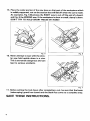
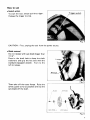
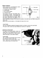
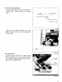
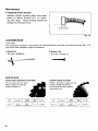
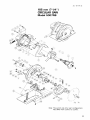
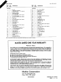
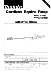
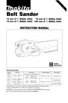
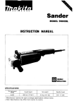
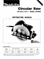
B
A
Circular Saw
185 mm (7-1/4")
MODEL 5007NB
INSTRUCTION MANUAL
Specifications
Max. cutting depth
diameter
1 8 5 mm
(7-114")
(1-314")
5,800
Rlmin.
2 9 5 mm
(1 1-518")
(11 Ibs)
Manufacturer reserves the right t o change specifications of parts and accessories without notice.
* Note: Specifications of parts and accessories may differ from country t o country.
IMPORTANT
SAFETY INSTRUCTIONS
(For All Tools)
WARNING: WHEN USING ELECTRIC TOOLS, BASIC SAFETY
PRECAUTIONS SHOULD ALWAYS BE FOLLOWED TO REDUCE
THE RISK OF FIRE, ELECTRIC SHOCK, AND PERSONAL
INJURY, INCLUDING THE FOLLOWING:
READ ALL INSTRUCTIONS.
1. KEEP WORK AREA CLEAN. Cluttered areas and benches invite injuries.
2. CONSIDER WORK AREA ENVIRONMENT. Don't use power tools in damp
or wet locations. Keep work area well lit. Don't expose power tools t o rain.
Don't use tool in presence of flammable liquids or gases.
3 . KEEP CHILDREN AWAY. All visitors should be kept away from work area.
Don't let visitors contact tool or extension cord.
4.STORE IDLE TOOLS. When not in use, tools should be stored in dry, and high
or locked-up place - out of reach of children.
5. DON'T FORCE TOOL. It will do the job better and safer at the rate for which
it was intended.
6 . USE RIGHT TOOL. Don't force small tool or attachment t o do the job of a
heavy-duty tool. Don't use tool for purpose not intended; for example, don't
use circular saw for cutting tree limbs or logs.
7. DRESS PROPERLY. Don't wear loose clothing or jewelry. They can be caught
in moving parts. Rubber gloves and non-skid footwear are recommended
when working outdoors. Wear protective hair covering t o contain long hair.
8. USE SAFETY GLASSES. Also use face or dust mask if cutting operation is
dusty.
9. DON'T ABUSE CORD. Never carry tool by cord or yank it to disconnect from
receptacle. Keep cord from heat, oil, and sharp edges.
IO. SECURE WORK. Use clamps or a vise to hold work. It's safer than using
your hand and it frees both hands to operate tool.
11. DON'T OVERREACH. Keep proper footing and balance at all times.
12. MAINTAIN TOOLS WITH CARE. Keep tools sharp and clean for better and
safer performance. Follow instructions for lubricating and changing accessories. Inspect tool cords periodically and if damaged, have repaired by authorized service facility. Inspect extension cords periodically and replace if
damaged. Keep handles dry, clean, and free from oil and grease.
13. DISCONNECT TOOLS. When not in use, before servicing, and when changing accessories, such as blades, bits, cutters.
2
14. REMOVE ADJUSTING KEYS AND WRENCHES. Form habit of checking to
see that keys and adjusting wrenches are removed from tool before turning
it on.
15. AVOID UNINTENTIONAL STARTING. Don't carry tool with finger on switch.
Be sure switch is OFF when plugging in.
16. EXTENSION CORDS. Make sure your extension cord is in good condition.
When using an extension cord, be sure to use one heavy enough t o carry
the current your product will draw. An undersized cord will cause a drop
in line voltage resulting in loss of power and overheating. Table 1 shows the
correct size to use depending on cord length and nameplate ampere rating.
If in doubt, use the next heavier gage. The smaller the gage number, the
heavier the cord.
TABLE 1 MINIMUM GAGE FOR CORD SETS
I
Total Length of Cord in Feet
0 - 25
26 - 50
Ampere Rating
Not More
More
Than
Than
0
6
10
12
~
~
6
10
12
16
51 - 100
101 - 150
A W G
18
18
16
14
16
16
16
12
;:
14
1
14
12
12
Not Recommended
17. OUTDOOR USE EXTENSION CORDS. When tool is used outdoors, use only
extension cords intended for use outdoors and so marked.
18. STAY ALERT. Watch what you are doing, use common sense. Don't operate
tool when you are tired.
19. CHECK DAMAGED PARTS. Before further use of the tool, a guard or other
part that is damaged should be carefully checked to determine that it will
operate properly and perform its intended function. Check for alignment of
moving parts, binding of moving parts, breakage of parts, mounting, and any
other conditions that may affect its operation. A guard or other part that
is damaged should be properly repaired or replaced by an authorized service center unless otherwise indicated elsewhere in this instruction manual.
Have defective switches replaced by authorized service center. Don't use
tool if switch does not turn it on and off.
20. GUARD AGAINST ELECTRIC SHOCK. Prevent body contact with grounded
surfaces. For example; pipes, radiators, ranges, refrigerator enclosures.
21 . REPLACEMENT PARTS. When servicing, use only identical replacement parts.
22. POLARIZED PLUGS. To reduce the risk of electric shock, this equipment has
a polarized plug (one blade is wider than the other). This plug will fit in a
polarized outlet only one way. If the plug does not fit fully in the outlet,
reverse the plug. If it still does not fit, contact a qualified electrician to install
the proper outlet. Do not change the plug in any way.
3
VOLTAGE WARNING: Before connecting the tool to a power source (receptacle,
outlet, etc.) be sure the voltage supplied is the same as that specified on the
nameplate of the tool. A power source with voltage greater than that specified
for the tool can result in SERIOUS INJURY to the user - as well as damage t o
the tool. If in doubt, DO NOT PLUG IN THE TOOL. Using a power source with
voltage less than the nameplate rating is harmful t o the motor.
ADDITIONAL SAFETY RULES
1. Wear hearing protection.
2. Keep Guards In Place and In Working Order.
Never wedge or tie lower guard open. Check operation of lower guard before
each use. Don’t use if lower guard does not close briskly over saw blade.
CAUTION: If saw is dropped, lower guard may be bent, restricting full return.
3.Do not use blades which are deformed or cracked.
4. Do not use blades of high speed steel.
5. Keep Blades Clean and Sharp.
Sharp blades minimize stalling and kickback.
6. DANGER: Keep Hands Away From Cutting Area.
Keep hands away from blades. Don’t reach underneath work while blade is
rotating. Don’t attempt t o remove cut material when blade is moving.
CAUTION: Blades coast after turn off.
7. Support Large Panels.
Large panels must be supported as shown in Fig. 1 to minimize the risk of
blade pinching and kickback.
When cutting operation requires the resting of the saw on the work piece,
the saw shall be rested on the larger portion and the smaller piece cut off.
To avoid kickback, do support board
or panel near t h e cut.
Don’t support board or panel away
from t h e cut.
Fig. 1
8. Use Rip Fence.
Always use a fence or straight edge guide when ripping.
4
Fig. 2
9. Guard Against Kickback.
Kickback occurs when the saw stalls rapidly and is driven back towards the
operator. Release switch immediately if blade binds or saw stalls. Keep blades
sharp. Support large panels as shown in Fig. 1. Use fence or straight edge
guide when ripping. Don't force tool. Stay alert exercise control. Don't remove
saw from work during a cut while the blade is moving.
NEVER place your hand or fingers
behind the saw. If kickback occurs,
the saw could easily jump backwards
over your hand, possibly causing
severe injury.
Fig. 3
IO. Lower Guard. Raise lower guard with the retracting handle.
1 1 . Adjustments. Before cutting be sure depth and bevel adjustments are tight.
12.Use Only Correct Blades In Mounting. Don't use blades with incorrect size
holes. Never use defective or incorrect blade washers or bolts.
13.Avoid Cutting Nails. Inspect for and remove all nails from lumber before
cutting.
14.When operating the saw, keep the
cord away from the cutting area and
position it so that it will not be caught
on the workpiece during the cutting
operation.
Operate with proper hand support,
proper workpiece support, and
supply cord routing away from the
work area.
A typical illustration of proper hand
support, workpiece support, and
supply cord routing.
Fig.
1
WARNING:
It is important to support the workpiece properly and to hold the saw firmly
to prevent loss of control which could cause personal injury. Fig. 4 illustrates
typical hand support of the saw.
5
15. Place the wider portion of the saw base on that part of the workpiece which
is solidly supported, not on the section that will fall off when the cut is made.
As examples, Fig. 5 illustrates the RIGHT way t o cut off the end of a board,
and Fig. 6 the WRONG way. If the workpiece is short or small, clamp it down.
DON'T TRY TO HOLD SHORT PIECE: BY HAND!
\
\
/
Fig.
Fig. 6
16. Never attempt to saw with the circular saw held upside down in a vise.
This is extremely dangerous and can
lead t o serious accidents.
I
I
Fig. 7
17. Before setting the tool down after completing a cut, be sure that the lower
(telescoping) guard has closed and the blade has come to a complete stop.
SAVE THESE INSTRUCTIONS.
6
How to use
0
Switch action
To start the tool, simply pull the trigger.
Release the trigger to stop.
Trigger switch
Fig. 4
CAUTION : First, unplug the tool from the power source.
0
Blade removal
Do not replace with saw blade bigger than
7- 114".
Press in the shaft lock to keep the shaft
stationary and grip the hex bolt with the
standard-equipped wrench. Turn to the
left to release.
Fig. 5
Then take off the outer flange. Raise the
safety guard as far as possible and slip the
saw blade off the shaft.
Saw blade
H bolt
___
I
I
1
8x-
Outer flanqe
\
Inner flanae
\
Fig. 6
7
0
Blade installation
Ta
Blade installation is performed by reversInner flange[-S
. aw
blade
ing the blade removal procedure.
a. Install inner flange on shaft.
b. Install blade.
c. Put on outer flange.
d. Install hex bolt.
This circular saw uses a saw blade with a
hole diameter of 5/8". The recessed side
of inner flange is kept on the blade motor
side when mounting (see figure). Raise
Fig. 7
the safetv ward as far as possible (i.e., as
when removing the blade), then mount the blade on the shaft with the Makita name side
facing you.
Secure the hex bolt tightly, or the blade will slip and not turn.
,
I
CAUTIONS:
Use only the Makita standard-equippedwrench to install or remove the saw blade.
The use of other tools may cause dangerous looseness or tightness.
0
Adjusting cutting depth
To adjust the cutting depth, loosen the
clamp lever on the depth guide then holding down the base with on hand raise or
lower the body for the desired depth.
CAUTIONS:
Use a shallow cutting depth when cutting
thin stock for cleaner, safer cuts.
After making the cutting depth adjustment, always secure the clamp lever.
Fig. 8
8
0
For the cutting position
Use the right notch of the front base for
straight cuts. The l e f t notch is for bevel
cuts.
F o r 45'
bevel cuts
4
cfuq:straight
Base plate
Fig. 9
Align the slot (saw position) on front
edge of base with your own cutting line
on the wood.
/
Fig. 10
0
For bevel work
Loosen the nut M6 on the bevel scale
plate on base front. Set for desired angle
(0- 45') by tilting accordingly, then retighten the nut M6 firmly.
Fig. 1 1
9
Maintenance
0
Replacing carbon brushes
Replace carbon brushes when they wear
down to about 6 mm (1/4") of sparking will occur. Both brushes should be
changed a t the same time.
I
U
6 mm ( 114")
Fig. 12
ACCESSORIES
CAUTION :
The accessories specified in this manual are recommended for use with your Makita Circular Saw. The
use of any other accessory might be hazardous.
0 Guide
rule
Wrench (13)
(Part No. 164095-8)
(Part No. 781 203-2)
SAW BLADE
Chisel tooth combination saw blade
Carbide-tipped saw blade
For rip and cross-cut work.
Most frequently used for
general carpentry.
Faster, smoother, longer sawing
without blade sharpening.
Cuts wood, drywall, plastics,
hard wood. etc.
NO.
185-76
10
Diameter
(ltlKA,
di7$:e,
(15.88mm,
5/8"
Part No.
20
721245-4
Apr - 0 9 ' 8 4
US
185 mm ( 7 - 1 / 4 ' )
CIRCULAR SAW
Model 5007NB
Note: The switch and other part configurations
may differ from country to country.
11
/
MODEL 5007NB
NO.
USED
Apr.-09-’84
ITEM
NO.
DESCRIPTION
1
1
3
4
5
6
7
0
9
10
11
12
13
14
15
16
17
19
20
1
1
1
1
1
4
2
1
3
1
2
2
1
1
2
1
1
21
22
23
24
25
26
27
28
29
30
2
1
1
1
1
1
1
1
1
1
US
DESCRIPTION
MACHINE
MACHINE
~
~
1
2
NO.
USED
31
Fan 92
ARMATURE ASSEMBLY
lAasembled Items 1 - 4. 34 & 351
l n ~ ~ l a t i oWasher
n
Ball Bearing 608LB
FIELD ASSEMBLY
P. H. Screw M4x12 (With Washer)
Double Pole Switch
P. H. Screw M4x25 (With Washer1
Rivet 0-5
Name Plate
P H Screw M5x50 IWith Washerl
Motor Housing
Carbon Brush
Brush Holder Cap
Cord Guard
Strain Relief
P. H. Screw M 4 x l 8 (With Washer1
Handle Cover
CORD ASSEMBLY
(Assembled Cord. Plug & Item 151
H. Bolt M5x55 (With Washer)
H. F H Bolt Max20
Outer Flange 4 0
Inner Flange 4 0
Retaining Ring S-42
Tension Spring 4
Bearing Retainer 22-36
Spindle
Woodruff Key 5
Ball Bearing 6202LLB
32
33
34
35
36
37
38
39
40
41
42
43
44
45
46
47
48
49
50
51
52
53
54
55
56
57
58
59
60
61
1
1
1
1
1
1
1
1
1
1
1
1
1
1
1
1
4
1
1
1
1
1
1
1
1
1
1
1
1
1
1
P. H. Screw M6x20
Rubber Sleeve 6
Blade Case
Ball Bearing 6201LLB
0“St Seal 12
Spindle Lock
H. Nut MB
P. H. Screw M4x8 (With Warherl
Lock Plate
Lever Plate
F. Washer 8
Needle Bearing 1010
Retaining Ring 5 - 1 5
Helical Gear 39
Ring 1 5
BBBrlng BOX
P. H. Screw M4x16 (With Washer)
Safely Cover
LWW
P. H. Screw M4x10 IWith Washer)
Screw M6x15
Spring Pin 6 - 4 0
C. S. N. Bolt M6x30
F. Washer 12
C. H. Screw M5x10
C. S N. Bolt MBx24
8858
Angular Plate
F Washer 6
S. Washer 6
N U M6
Note The switch and other part Specifications may differ from country to country
MAKmA LIMITED ONE YEAR WARRANTY
Warranty Policy
Every Makita tool is thoroughly inspected and tested before leaving the factory. It is warranted to
be free of defects from workmanship and materials for the period of ONE YEAR from the date of
original purchase. Should any trouble develop during this one-year period, return the COMPLETE
tool, freight prepaid, to one of Makita’s Factory or Authorized Service Centers. If inspection shows
the trouble is caused by defective workmanship or material, Makita will repair (or at our option,
replace) without charge.
This Warranty does not apply where:
repairs have been made or attempted by others:
repairs are required because of normal wear and tear:
The tool has been abused, misused or improperly maintained ;
0 alterations have been made to the tool.
IN NO EVENT SHALL MAKlTA BE LIABLE FOR ANY INDIRECT, INCIDENTAL OR CONSEQUENTIAL DAMAGES FROM THE SALE OR USE OF THE PRODUCT. THIS DISCLAIMER
APPLIES BOTH DURING AND AFTER THE TERM OF THIS WARRANTY.
MAKlTA DISCLAIMS LIABILITY FOR ANY IMPLIED WARRANTIES, INCLUDING IMPLIED
WARRANTIES O F “MERCHANTABILITY” AND “FITNESS FOR A SPECIFIC PURPOSE,”
AFTER THE ONE-YEAR TERM O F THIS WARRANTY.
This Warranty gives you specific legal rights, and you may also have other rights which vary from
state to state. Some states do not allow the exclusion or limitation of incidental or consequential
damages, so the above limitation or exclusion may not apply to you. Some states do not allow
limitation on how long an implied warranty lasts, so the above limitation may not apply to you.
-
i
__L
Makita Corporation
3-11-8, Sumiyoshi-cho,
Anjo, Aichi 446 Japan
883333A993
PRINTED IN JAPAN
1995
-4 - N