1
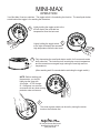
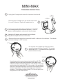
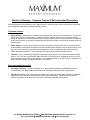
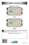
MINI-MAX INSTALLATION PROPER INSTALLATION IS IMPORTANT. IF YOU NEED ASSISTANCE,CONSULT A CONTRACTOR, ELECTRICIAN OR TELEVISION ANTENNA INSTALLER (CHECK WITH YOUR LOCAL BUILDING SUPPLY, OR HARDWARE STORE FOR REFERRALS). TO PROMOTE CONFIDENCE, PERFORM A TRIAL WIRING BEFORE INSTALLATION. 1 WOOD SCREWS 2 CAULK 8" MIN CABLE CLIP DRIP LOOP Mount the temperature sensor assembly with the two large wood screws. Select a location that is protected from direct sunlight and sheltered. (A north exposure, six feet above the ground will give the best results.) Form a drip loop with the wire at least eight inches below the exit from the sensor and at least eight inches below the point of entry into the building. Anchor any exposed wire with insulated cable clips. Run the wire through the building to the location where the indicator will be located. Caulk any holes when done. LL WA Mount the Brass Readout directly over the Feed-Thru-Hole to avoid crimping the wire under the lip. We recommend mounting the Readout on one of our pre-drilled and 3 centered panels. GREEN GROUNDING CORD PRE-DRILLED PANEL CABLE-HOLE SCREW TO TEMPERATURE SENSOR AC ADAPTOR SCREW 4 Feed the AC Adaptor Cord, Green Grounding Cord and Sensor wire to the Indicator. Connect the two temperature sensor wires to the appropriate terminals (HEX NUTS) as shown in the illustration. The polarity does not matter. Connect the AC adaptor wires to their appropriate terminals (HEX NUTS) as shown in the illustration. The polarity does not matter for these. To prevent static from causing bad readings it is necessary to "EARTH GROUND" you Mini-Max. Proceed as follows: -Turn off the circuit-breaker to the outlet where the ground cord is attached. -Remove the outlet cover screw. -Insert the outlet cover screw through the lug on the green grounding cord and reinsert the outlet cover screw. -Turn on the circuit-breaker to the outlet. -Plug in the AC Adaptor. -Reset the memories as described in the operating instructions (next page). 5 GREEN GROUNDING CORD 30 Samuel Barnett Boulevard New Bedford, MA 02745 (508) 995-2200 LUG SCREW MINI-MAX OPERATION Your Mini-Max II has two switches. The toggle switch is for selecting the function. The small push button switch behind the toggle is for resetting the memories. 1 Lightly holding the toggle switch to the left will display the recorded low temperature since the last reset. Lightly holding the toggle switch 2 to the right will display the recorded high temperature since the last reset. 3 Fully depressing the small push button switch for five seconds resets both memories. The instrument will now display current temperature and the memories once again begin storing the new high and low temperatures. (After resetting wait 10 seconds before activating the toggle switch.) NOTE: Before reading your thermometer, you should lightly tap the case with your finger. A TAP change of 1-2 degrees is a common occurance with any slow moving precision meter movement. 4 The trend register needle can be set by turning the center knob on the indicator dial. 30 Samuel Barnett Boulevard New Bedford, MA 02745 (508) 995-2200 MINI-MAX TROUBLE SHOOTING 1 Unplug the AC adaptor and remove the instrument from the wall. AC ADAPTOR AC VOLTMETER Disconnect the AC adaptor from the indicator and connect it to an AC Voltmeter. Plug the AC adaptor back in. 3 If working properly the AC adaptor will deliver 11.5 to 18VAC. If not working properly please contact the factory. If the AC adaptor is working properly, continue with the next steps. 4 Unplug the AC adaptor and reconnect it to the indicator. Plug the AC adaptor back into a 110V outlet. 5 2 Disconnect the sensor wires from terminals #1 and #2 on the back of the indicator. The indicator pointer should drop to -35 F or below. 6 Use a jumper wire (a paper clip will do) to connect across the sensor terminals #1 and #2. The indicator should read 120 F. If so, disconnect this jumper and proceed to the next step. Use a jumper wire to connect across terminals #2 and #3. The 7 calibration test point has been hand-written on the back of the indicator just above terminals #2 and #3. If the indicator is in proper working order it will read within 2 F of this number. We recommend that you re-mount the instrument in this mode for several hours and observe it periodically. This will help to detect most intermittent problems. If the indicator registers within 2 F of the test point, then the problem is in the sensor or wire. 30 Samuel Barnett Boulevard New Bedford, MA 02745 (508) 995-2200 IMPORTANT ADDITIONAL INFORMATION Components: Along with the indicator, the following components are included with this instrument: AC Adaptor: This instrument requires its own AC Adaptor. Due to the various power requirements of each Maximum instrument, attempting to run more than one instrument on a single adaptor could cause improper operation and/or damage to the instrument(s) thereby voiding your 5-year warranty. Brass Case: Your brass case is solid brass A70-30 Holloware quality, with a durable lacquer finish. It is in fact a piece of jewelry and should be treated as such. It should be cleaned at least once a week to keep airborne pollutants (dust, etc…) and any moisture from collecting on the case thereby attacking the lacquer. At no time should you use an abrasive cleaner or cloth on the brass case. Simply use a soft cloth or soft paper towel with a mild glass cleaner to wipe the case clean. If your instruments are in a summer home, and you are not able to clean them regularly, simply lay a small cloth or towel across the top two-thirds so that dust cannot settle on the finish. Specifications: All instrumentation or measuring devices have accuracy tolerances and specifications. Making comparisons between different pieces of equipment is appropriate provided the specified accuracies of both are known. Temperature (Indicator) Temperature (Sensor) Measurement Range -35 to 120°F Guaranteed Accuracy ±.5°C., 1°F ±.5°C., 1°F Electrical Damage – Common Causes & Recommended Prevention Electrical damage can be caused by many different factors. Below are some of the more common causes and some suggested methods of minimizing potential problems. Common Causes: Storm Activity – lightening in your area can do damage to your instruments in different ways. The obvious way is due to a direct or nearby strike. In addition, lightening storms, dust storms, dry snowstorms and strong dry winds can all cause static electricity to build up on and around your external sensors. Regardless of the cause, this built up electricity can discharge itself through the cable connecting the external sensors to the instrument. Power Surges – A surge may come from the electric company’s switching generators or power grids, from local industries or after power interruption when accumulated power suddenly surges back through AC lines. Even the on-and-off switching of large electrical appliances, such as refrigerators or clothes dryers can create damaging fluctuations. This is especially true with sensitive weather recording devices. Yourself – Are you constantly giving and/or receiving a shock every time you touch a doorknob or another person? If so, you have a great deal of static electricity in your environment. Depending on where you live, static electricity may be a year round problem or only a seasonal problem. In either case, it is possible for a person to carry enough of a charge to damage an instrument. Recommended Prevention: Use Surge Protectors – For the AC adapter, a UL 1449 rated surge protector with EMI/RFI filtering is recommended. This rating will be clearly listed on the packaging of all good quality surge protector. Discharge Yourself – If the instruments are located in an environment where static electricity is a problem, make sure that you discharge yourself before touching the instrument(s). The shock that you get from touching a doorknob or another person can often be sufficient to damage an instrument. 30 SAMUEL BARNET BOULEVARD NEW BEDFORD, MASSACHUSETTS 02745 U.S.A. TEL. 508.995.2200 WWW.MAXIMUM-INC.COM FAX 800.989.2580