1
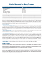
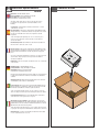
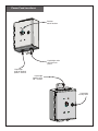
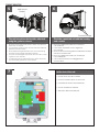
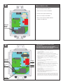
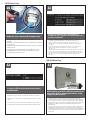
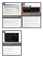
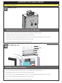
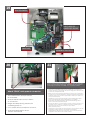
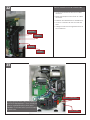
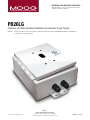
Installation and Operation Instructions
Before attempting to connect or operate this product, please
read these instructions completely.
PB26LG
Aluminum City-Wide Surveillance Wireless Communication Power Solution
PB26LG..........Liberty Series wireless power box that includes a cellular router and power supply. 110/220VAC input. Designed to work with Moog IP Ready Series of IP camera housings
Moog Inc.
Sensor and Surveillance Systems
© 2013, Moog Inc. All Rights Reserved
3650 Woodhead Drive Northbrook, IL. USA 60062
+1.847.498.0700 Fax: +1.847.498.1258 www.moogS3.com
81-IN5459 111913
IMPORTANT SAFEGUARDS
1
Read these instructions.
2
Keep these instructions.
3
Heed all warnings
4
Follow all instructions.
5
Do not use this apparatus near water.
6
Clean only with damp cloth.
7
Do not block any of the ventilation openings. Install in accordance with the
CAUTION
RISK OF ELECTRIC SHOCK
DO NOT OPEN
manufacturers instructions.
8
9
SAFETY PRECAUTIONS
Cable Runs- All cable runs must be within permissible distance.
CAUTION: TO REDUCE THE RISK OF
ELECTRIC SHOCK, DO NOT REMOVE
COVER ( OR BACK). NO USER- SERVICEABLE PARTS INSIDE. REFER SEVICING
TO QUALIFIED SERVICE PERSONNEL.
Mounting - This unit must be properly and securely mounted to a supporting
structure capable of sustaining the weight of the unit.
Accordingly:
a. This installation should be made by a qualified service person and should conform
to all local codes.
b. Care should be exercised to select suitable hardware to install the unit, taking into
account both the composition of the mounting surface and the weight of the unit.
10 Do not install near any heat sources such as radiators, heat registers, stoves, or other
apparatus ( including amplifiers) that produce heat.
11 Do not defeat the safety purpose of the polarized or grounding-type plug. A
polarized plug has two blades with one wider than the other. A grounding type
plug has two blades and a third grounding prong. The wide blade or the third
prong are provided for your safety. When the provided plug does not fit into your
outlet, consult an electrician for replacement of the obsolete outlet.
12 Protect the power cord from being walked on or pinched particularly at plugs,
convenience receptacles, and the point where they exit from the apparatus.
13 Only use attachment/ accessories specified by the manufacturer.
14 Use only with a cart, stand, tripod, bracket, or table specified by the manufacturer,
or sold with the apparatus. When a cart is used, use caution when moving the cart/
apparatus combination to avoid injury from tip-over.
15 Unplug this apparatus during lighting storms or when unused for long periods of time.
16 Refer all servicing to qualified service personnel. Servicing is required when the
apparatus has been damaged in any way, such as power-supply cord or plug is
damaged, liquid has been spilled of objects have fallen into the apparatus, the
The lightning flash with an arrowhead symbol,
within an equilateral triangle, is intended to
alert the user to the presence of non-insulated
“dangerous voltage” within the product’s
enclosure that may be of sufficient magnitude
to constitute a risk to persons.
Este símbolo se piensa para alertar al usuario a la presencia
del “voltaje peligroso no-aisIado” dentro del recinto de los
productos que puede ser un riesgo de choque eléctrico.
Ce symbole est prévu pour alerter I’utilisateur à la presence
“de la tension dangereuse” non-isolée dans la clôture de
produits qui peut être un risque de choc électrique.
Dieses Symbol soll den Benutzer zum Vorhandensein der
nicht-lsolier “Gefährdungsspannung” innerhalb der
Produkteinschließung alarmieren die eine Gefahr des
elektrischen Schlages sein kann.
Este símbolo é pretendido alertar o usuário à presença “di
tensão perigosa non-isolada” dentro do cerco dos produtos
que pode ser um risco de choque elétrico.
Questo simbolo è inteso per avvertire I’utente alla presenza
“di tensione pericolosa” non-isolata all’interno della
recinzione dei prodotti che può essere un rischio di scossa
elettrica.
apparatus has been exposed to rain or moisture, does not operate normally, or
has been dropped.
Be sure to periodically examine the unit and the supporting structure to make sure that the integrity
of the installation is intact. Failure to comply with the foregoing could result in the unit separating
from the support structure and falling, with resultant damages or injury to anyone or anything struck
by the falling unit.
UNPACKING
Unpack carefully. Electronic components can be
damaged if improperly handled or dropped. If an item
appears to have been damaged in shipment, replace
it properly in its carton and notify the shipper.
Be sure to save:
1 The shipping carton and packaging material.
They are the safest material in which to make future
shipments of the equipment.
2 These Installation and Operating Instructions.
SERVICE
If technical support or service is needed, contact us at
the following number:
TECHNICAL SUPPORT
AVAILABLE 24 HOURS
1 - 800 - 554 -1124
The exclamation point within an equilateral
triangle is intended to alert the user to
presence of important operating and
maintenance (servicing) instructions in the
literature accompanying the appliance.
Este símbolo del punto del exclamation se piensa para
alertar al usuario a la presencia de instrucciones importantes
en la literatura que acompaña la aplicación.
Ce symbole de point d’exclamation est prévu pour alerter
l’utilisateur à la presence des instructions importantes dans
la littérature accompagnant l’appareil.
Dieses Ausruf Punktsymbol soll den Benutzer zum
Vorhandensein de wichtigen Anweisungen in der Literatur
alarmieren, die das Gerät begleitet.
Este símbolo do ponto do exclamation é pretendido alertar o
usuário à presença de instruções importantes na literatura
que acompanha o dispositivo.
Questo simbolo del punto del exclamaton è inteso per
avvertire l’utente alla presenza delle istruzioni importanti nella
letteratura che accompagna l'apparecchio.
MADEIN
USA
BUY AMERICA COMPLIANT • COUNTRY OF ORIGIN U.S.A.
Product Warranty Registration
Register Your Products Online
www.moogS3.com/technical-support/product-registration
Moog values your patronage. We are solely committed to providing you with the highest quality products and
superior customer service. With 3-Year and 5-Year warranties (depending on the product purchased) we stand
behind every product we sell.
See full warranty details at www.moogS3.com/technical-support/warranty-plan/
:
• Simple and Trouble-Free RMA process
• Product / software updates
• Special promotions
• Eliminate the need to archive purchase documents such as receipts, purchase orders, etc.
Limited Warranty for Moog Products
Moog - Decatur Operations, subsequently referred to as “Manufacturer,” warrants these products to be free from defects in material or workmanship as follows:
PRODUCT CATEGORY
PARTS \ LABOR
All Enclosures and Electronics
Five (5) Years
Accessory Brackets
Five (5) Years
Controllers
Three (3) Years
Power Supplies / IR Illuminators
Three (3) Years
Poles / PolEvators / CamEvator
Three (3) Years
Warrior Series™ / Q-View™
Three (3) Years
™
Three (3) Years 6 months if used in auto scan / tour operation
SView Series
™
DeputyDome , NiteTrac , Igloo Dome, PurgeDome
Three (3) Years 6 months if used in auto scan / tour operation
EXO Series™ Dome and Fixed Camera Systems*
Three (3) Years 6 months if used in auto scan / tour operation
EXO Series™ GeminEye Visible and Thermal Camera Systems
One (1) Year
™
™
™
During the labor warranty period, to repair the Product, Purchaser will either return the defective product, freight prepaid, or deliver it to Manufacturer at Moog Decatur
Operations, 2525 Park Central Boulevard, Decatur, Georgia, 30035. The Product to be repaired is to be returned in either its original carton or a similar package affording
an equal degree of protection with a RMA # (Return Materials Authorization number) displayed on the outer box or packing slip. To obtain a RMA# you must contact our
Technical Support Team at 800.554.1124, extension 101. Manufacturer will return the repaired product freight prepaid to Purchaser. Manufacturer is not obligated to
provide Purchaser with a substitute unit during the warranty period or at any time. After the applicable warranty period, Purchaser must pay all labor and/or parts charges.
The limited warranty stated in these product instructions is subject to all of the following terms and conditions.
TERMS AND CONDITIONS
1. NOTIFICATION OF CLAIMS: WARRANTY SERVICE: If Purchaser believes that the Product is defective in material or workmanship, then written notice with an explanation
of the claim shall be given promptly by Purchaser to Manufacturer. All claims for warranty service must be made within the warranty period. If after investigation,
Manufacturer determines the reported problem was not covered by the warranty, Purchaser shall pay Manufacturer for the cost of investigating the problem at its then
prevailing per incident billable rate. No repair or replacement of any Product or part thereof shall extend the warranty period of the entire Product. The specific warranty on
the repaired part only shall be in effect for a period of ninety (90) days following the repair or replacement of that part or the remaining period of the Product parts warranty,
whichever is greater.
2. EXCLUSIVE REMEDY: ACCEPTANCE: Purchaser’s exclusive remedy and Manufacturer’s sole obligation is to supply (or pay for) all labor necessary to repair any Product
found to be defective within the warranty period and to supply, at no extra charge, new or rebuilt replacements for defective parts.
3. EXCEPTIONS TO LIMITED WARRANTY: Manufacturer shall have no liability or obligation to Purchaser with respect to any Product requiring service during the warranty
period which is subjected to any of the following: abuse, improper use, negligence, accident, or acts of God (i.e., hurricanes, earthquakes), modification, failure of the
end-user to follow the directions outlined in the product instructions, failure of the end-user to follow the maintenance procedures recommended by the International Security
Industry Organization, written in product instructions, or recommended in the service manual for the Product. Furthermore, Manufacturer shall have no liability where a
schedule is specified for regular replacement or maintenance or cleaning of certain parts (based on usage) and the end-user has failed to follow such schedule; attempted
repair by non-qualified personnel; operation of the Product outside of the published environmental and electrical parameters, or if such Product’s original identification
(trademark, serial number) markings have been defaced, altered, or removed. Manufacturer excludes from warranty coverage Products sold AS IS and/or WITH ALL FAULTS
and excludes used Products which have not been sold by Manufacturer to the Purchaser. All software and accompanying documentation furnished with, or as part of the
Product is furnished “AS IS” (i.e., without any warranty of any kind), except where expressly provided otherwise in any documentation or license agreement furnished with
the Product. ANY COST ASSOCIATED WITH REMOVAL OF DEFECTIVE PRODUCT AND INSTALLATION OF REPLACEMENT PRODUCT IS NOT INCLUDED IN THIS WARRANTY.
4. PROOF OF PURCHASE: The Purchaser’s dated bill of sale must be retained as evidence of the date of purchase and to establish warranty eligibility.
DISCLAIMER OF WARRANTY
EXCEPT FOR THE FOREGOING WARRANTIES, MANUFACTURER HEREBY DISCLAIMS AND EXCLUDES ALL OTHER WARRANTIES, EXPRESS OR IMPLIED, INCLUDING, BUT
NOT LIMITED TO ANY AND/OR ALL IMPLIED WARRANTIES OF MERCHANTABILITY, FITNESS FOR A PARTICULAR PURPOSE AND/OR ANY WARRANTY WITH REGARD TO ANY
CLAIM OF INFRINGEMENT THAT MAY BE PROVIDED IN SECTION 2-312(3) OF THE UNIFORM COMMERCIAL CODE AND/OR IN ANY OTHER COMPARABLE STATE STATUTE.
MANUFACTURER HEREBY DISCLAIMS ANY REPRESENTATIONS OR WARRANTY THAT THE PRODUCT IS COMPATIBLE WITH ANY COMBINATION OF NON-MANUFACTURER
PRODUCTS OR NON-MANUFACTURER RECOMMENDED PRODUCTS PURCHASER MAY CHOOSE TO CONNECT TO THE PRODUCT.
LIMITATION OF LIABILITY
THE LIABILITY OF Manufacturer, IF ANY, AND PURCHASER’S SOLE AND EXCLUSIVE REMEDY FOR DAMAGES FOR ANY CLAIM OF ANY KIND WHATSOEVER, REGARDLESS
OF THE LEGAL THEORY AND WHETHER ARISING IN TORT OR CONTRACT, SHALL NOT BE GREATER THAN THE ACTUAL PURCHASE PRICE OF THE PRODUCT WITH RESPECT
TO WHICH SUCH CLAIM IS MADE. IN NO EVENT SHALL MANUFACTURER BE LIABLE TO PURCHASER FOR ANY SPECIAL, INDIRECT, INCIDENTAL, OR CONSEQUENTIAL
DAMAGES OF ANY KIND INCLUDING, BUT NOT LIMITED TO, COMPENSATION, REPLACEMENT LABOR COSTS, REIMBURSEMENT, OR DAMAGES ON ACCOUNT OF THE LOSS
OF PRESENT OR PROSPECTIVE PROFITS OR FOR ANY OTHER REASON WHATSOEVER.
* NOTE
Moog will repair or replace, at its option, any equipment which is damaged by transient voltage surge/spike or lightning strike (an “Occurrence”), while properly connected
to wired AC power line with protective ground. Any repair or modification of the equipment done by someone other than Moog voids the warranty.
Form 500-911 081913
Electrical Specifications
PB26LG
English
Input Power: 110 VAC/220VAC 1A/.5A
Power Consumption: 1Amp (120 Watts) at 120 VAC
Power Output: 96 VA at 24 VAC 52 Watts
Heater/Blower 32 Watts Camera Power
An all pole main switch with a contact of at least 3mm in each
pole shall be incorporated in the electrical installation of the
building.
Tools Required: .150” Flathead Screwdriver 7/16 Wrench or Socket
9/16 Wrench or Socket
Español
Energía De Entrada: 110 Consumo De Energía de VAC/220VAC 1A/.5A:
1Amp (120 vatios) en 120 VAC de salida de energía: VA 96 en 24 VAC
52 vatios de Heater/Blower 32 vatios de energía de la cámara
fotográfica
Todo el interruptor principal del poste con un contacto de por lo
menos 3m m en cada poste será incorporado en la instalación
eléctrica del edificio.
Herramientas Requeridas: destornillador de cabeza llana del 150"7/16
llave de la llave o del zócalo 9/16 o zócalo
Français
Puissance D'entrée : 110 Puissance D'Énergie de VAC/220VAC 1A/.5A :
1Amp (120 watts) à 120 VCA de rendement de puissance: VA 96 à 24
VCA 52 watts de Heater/Blower 32 watts de puissance d'appareilphoto
Un tout le commutateur principal de poteau avec un contact au moins
de 3mm dans chaque poteau sera incorporé dans l'installation
électrique du bâtiment.
Outils Requis: tournevis à tête plate de 150"7/16 clé de clé ou de douille
9/16 ou douille
Deutsch
Zugeführte Energie: 110 VAC/220VAC 1A/.5A
Leistungsaufnahme: 1Amp (120 Watt) bei 120 VAC
Abgabeleistung: VA 96 bei 24 VAC 52 Watt
Heater/Blower 32 Watt Kamera-Energie
Ein aller Pfostenhauptschalter mit einem Kontakt von 3mm mindestens
in jedem Pfosten wird in der elektrischen Installation des Gebäudes
enthalten.
Werkzeuge Erforderten: 150"Flachkopfschraubenzieher 7/16 Schlüsseloder Einfaßung 9/16 Schlüssel oder Einfaßung
Portuguese
Poder De Entrada: 110 Consumo De Potência de VAC/220VAC 1A/.5A:
1Amp (120 watts) em 120 VAC de saída de poder: VA 96 em 24 VAC
52 watts de Heater/Blower 32 watts de poder da câmera
Todo o interruptor principal do pólo com um contato ao menos de
3mm em cada pólo será incorporado na instalação elétrica do edifício.
As Ferramentas Requereram: chave de fenda flathead do 150"7/16 de
chave da chave ou do soquete 9/16 ou soquete
Italiano
Alimentazione in ingresso Di Entrata: 110 Assorbimento di corrente Di
energia di VAC/220VAC 1A/.5A: 1Amp (120 watt) a 120 VCA di uscita
di alimentazione: VA 96 a 24 VCA 52 watt di Heater/Blower 32 watt di
alimentazione della macchina fotografica
Tutto l'interruttore principale del palo con un contatto almeno di 3mm
in ogni palo sarà compreso nell'installazione elettrica della costruzione.
Attrezzi Richiesti: cacciavite a testa piatta del 150"7/16 di chiave dallo
zoccolo o dalla chiave 9/16 o zoccolo
Contents of Box
Power Feed Locations:
Pendant
mount location
Liquid tight strain
relief for main
power
Liquid tight
plug for optional
power / antenna
Liquid tight
modem cover
3G - 4G units
Liquid tight
security latch
WALL MOUNTING
1
Attach unit securely with (4) ⅜” bolts.
• Ate la unidad con seguridad con (4) pernos del ⅜ los”.
• Attachez l'unité solidement avec (4) boulons
de ⅜ des ».
• Bringen Sie Maßeinheit sicher mit (4) ⅜“
Schraubbolzen an.
• Una a unidade firmemente com (4) parafusos do ⅜”.
• Attacchi saldamente l'unità con (4) bulloni del ⅜„.
3
POLE MOUNTING
2
Step One: Attach the pole clips to the mounting
tabs as shown. Use hardware provided.
• Paso uno: Ate los clips del poste a las lengüetas del montaje
como se muestra. Utilice el hardware proporcionado.
• Étape une : Attachez les agrafes de poteau aux étiquettes de
support comme montrées. Utilisez le matériel fourni.
• Schritt einer: Bringen Sie die Pfostenclips zu den
Montagevorsprüngen wie gezeigt an. Benutzen Sie die
bereitgestellte Hardware.
• Etapa uma: Una os grampos do pólo às abas da montagem
como mostradas. Use a ferragem fornecida.
• Punto uno: Attacchi le clip del palo alle linguette del
montaggio come indicate. Utilizzi i fissaggi forniti.
4
Step Two: PB26LG is ready to mount. Use slots
to attach steel straps.
Step Three: Use steel straps to mount the
unit to a pole.
• Paso dos: PB26LG está listo para montar. Utilice las
ranuras para atar las correas de acero.
• Étape deux : PB26LG est prêt à monter. Employez les
fentes pour attacher les courroies en acier.
• Schritt zwei: PB26LG ist bereit anzubringen. Benutzen Sie
Schlitze, um Stahlbügel anzubringen.
• Etapa dois: PB26LG está pronto para montar. Use
entalhes para unir as cintas de aço.
• Punto due: PB26LG è pronto a montare. Usi le
scanalature per attaccare le cinghie d'acciaio.
• Paso tres: Utilice las correas de acero para montar la
unidad a un poste.
• Étape trois : Employez les courroies en acier pour
monter l'unité à un poteau.
• Schritt drei: Benutzen Sie Stahlbügel, um die Maßeinheit
zu einem Pfosten anzubringen.
• Etapa três: Use as cintas de aço para montar a
unidade a um pólo.
• Punto tre: Usi le cinghie d'acciaio per montare l'unità
ad un palo.
PENDANT MOUNTING
5
Wall Mount
Gasket
6
Conduit Fittings
The wall mount bracket must be attached
using the gasket as shown.
This is the assembled unit with the housing
and conduit.
• El soporte del montaje de la pared se debe atar usando la
junta como se muestra.
• La parenthèse de bâti de mur doit être attachée utilisant la
garniture comme montrée.
• Der Wandeinfassungshaltewinkel muss unter Verwendung
der Dichtung wie gezeigt angebracht werden.
• O suporte da montagem da parede deve ser unido usando
a gaxeta como mostrado.
• La staffa del supporto della parete deve essere attaccata
per mezzo della guarnizione come indicata.
• Ésta es la unidad montada con la cubierta
y el conducto.
• C'est l'unité assemblée avec le logement
et le conduit.
• Dieses ist die zusammengebaute Maßeinheit mit dem
Gehäuse und dem Rohr.
• Esta é a unidade montada com a carcaça
e a canalização.
• Ciò è l'unità montata con l'alloggiamento
ed il condotto.
7
Inside view of the unit.
• Dentro de la vista de la unidad.
• Dessus à l'intérieur de la vue de l'unité.
• Innerhalb der Ansicht der Maßeinheit.
• Dentro da ideia da unidade.
• All'interno della vista dell'unità.
8
Remove barrier cover.
• Quite la cubierta de la barrera.
• Enlevez la couverture de barrière.
• Entfernen Sie Sperrenabdeckung.
• Remova a tampa da barreira.
• Rimuova la copertura della barriera.
o della vista dell'unità.
Remove
barrier
cover
9
ON/OFF switch
(will not turn off
wireless circuit)
1. Move the 115//240VAC selector switch (3) to the
desired position
2. Insure that the ON/OFF switch (2) is in the off position
3. Attach the in coming “main” power to the 120/240 VAC input
4. Move the ON/OFF switch (2) to the ON position.
120/240VAC
Aux. output
•
1. Mueva el interruptor de selector 115//240VAC (3) a
la posición deseada
2. Asegure que el interruptor CON./DESC. (2) está en la
posición de reposo
3. Ate en energía “principal” que viene a la entrada de 120/240
VAC 4. Mueva el interruptor CON./DESC. (2) a la posición de trabajo.
•
1. Déplacez le sélecteur 115//240VAC (3) à la position désirée
2. Assurez-vous que le commutateur "MARCHE/ARRÊT" (2) est dans la
position de repos
3. Attachez dans la prochaine puissance « principale » à l'entrée de
120/240 VCA
4. Déplacez le commutateur "MARCHE/ARRÊT" (2) à la
position de fonctionnement.
•
1. Verschieben Sie den Schalter des Wähl 115//240VAC (3) auf die
gewünschte Position
2. Versichern Sie, dass der Ein/Aus-Schalter (2) in der Ausschaltstellung ist
3. Bringen Sie in kommender „Haupt“ Energie zum 120/240 VACEingang an
4. Verschieben Sie den Ein/Aus-Schalter (2) auf die Arbeitsstellung.
•
1. Mova o interruptor de seletor 115//240VAC (3) para a
posição desejada
2. Segure que o interruptor DE LIGAR/DESLIGAR (2) está no
posição de repouso
3. Una no poder “principal” de vinda à entrada de 120/240 de VAC
4. Mova o interruptor DE LIGAR/DESLIGAR (2) para o
posição de functionamento.
•
1. Sposti l'interruttore di selettore 115//240VAC (3) alla posizione voluta
2. Assicuri che l'interruttore acceso/spento (2) è nella posizione di riposo
3. Attacchi nel potere “principale„ venente all'input da 120/240 di VCA
4. Sposti l'interruttore acceso/spento (2) alla posizione di funzionamento.
24VAC
Aux. output
120/240VAC
input
115/240VAC
selector switch
12VDC output
3G/4G Camera Prep
10
11
Assign your camera the static TCP/IP address of
192.168.1.50 with a subnet mask of 255.255.255.0 and a
gateway of 192.168.1.1.
Connect to your camera with a laptop or pc
• Conecte con su cámara con un ordenador portátil o
una PC.
• Reliez à votre appareil-photo à un ordinateur portable
ou à un PC.
• Schließen Sie an Ihre Kamera an einen Laptop oder an
einen PC an.
• Conecte a sua câmera com um portátil ou um PC.
• Colleghi alla vostra macchina fotografica con un
computer portatile o un pc.
•
•
•
•
•
Asigne a su cámara la dirección estática del TCP/IP de 192.168.1.50 con
un subnet mask de 255.255.255.0 y una entrada de 192.168.1.1.
Assignez à votre appareil-photo l'adresse statique de TCP/IP de
192.168.1.50 avec un subnet mask de 255.255.255.0 et un passage de
192.168.1.1.
Weisen Sie Ihrer Kamera die statische IP-Adresse von 192.168.1.50 mit
einem subnet mask von 255.255.255.0 und einem Zugang von
192.168.1.1 zu.
Atribua a sua câmera o endereço de estática do TCP/IP de 192.168.1.50
com um subnet mask de 255.255.255.0 e uma passagem de 192.168.1.1.
Assegni alla vostra macchina fotografica l'indirizzo statico del TCP/IP di
192.168.1.50 con un subnet mask di 255.255.255.0 e un ingresso di
192.168.1.1.
USB 3G/4G Card Prep
12
Change to HTTP port from the default port 80 to
the port 12345.
• Cambie al puerto del HTTP del puerto 80 del defecto al puerto 12345.
• Changez en le port de HTTP du port 80 de défaut en port 12345.
• Ändern Sie zum HTTP-Hafen vom Rückstellungshafen 80 zum Hafen
12345.
• Mude ao porto do HTTP do porto 80 do defeito ao porto 12345.
• Cambi all'orificio del HTTP dall'orificio 80 di difetto all'orificio 12345.
13
When ordering your service with your provider, have
them add a static ip address to the service <extra
charge may be involved>
• Al pedir su servicio con su abastecedor, haga que agreguen un IP
address estático al servicio (el recargo puede estar implicado).
• En commandant votre service avec votre fournisseur, faites-ajouter les
un IP address statique au service (le supplément peut être impliqué).
• Wenn Sie Ihren Service mit Ihrem Versorger bestellen, lassen Sie sie ein
statisches IP address dem Service hinzufügen (Extragebühr kann
beteiligt sein) .
• Ao requisitar seu serviço com seu fornecedor, mande-os adicionar um
IP address de estática ao serviço (a sobretaxa pode ser involvida.
• Nell'ordinare il vostro servizio con il vostro fornitore, facciali aggiungere
un IP address statico al servizio (la carica supplementare può essere
implicata).
14
Some users may require WiFi access to the unit as well. Connect to the WiFi
network by selecting the SSID that contains the word Videolarm and a
combination of three letters and numbers. An example is Videolarm2A0 as
shown above. The encryption key for the network is password.
•
•
•
•
•
Algunos usuarios pueden requerir el acceso de WiFi a la unidad también. Conecte con la red de
WiFi seleccionando el SSID que contiene la palabra Videolarm y una combinación de tres letras y
números. Un ejemplo es Videolarm2A0 como se muestra arriba. La llave de encripción para la red
es contraseña.
Quelques utilisateurs peuvent avoir besoin de l'accès de WiFi à l'unité aussi bien. Reliez au réseau de
WiFi en choisissant le SSID qui contient le mot Videolarm et une combinaison de trois lettres et
nombres. Un exemple est Videolarm2A0 comme montré ci-dessus. La clef de chiffrage pour le
réseau est mot de passe.
Einige Benutzer können WiFi Zugang zur Maßeinheit außerdem fordern. Schließen Sie an das WiFi
Netz an, indem Sie das SSID vorwählen, das das Wort Videolarm und eine Kombination von drei
Buchstaben und von Zahlen enthält. Ein Beispiel ist Videolarm2A0 wie gezeigt oben. Der
Verschlüsselungschlüssel für das Netz ist Kennwort.
Alguns usuários podem exigir o acesso de WiFi à unidade também. Conecte à rede de WiFi
selecionando o SSID que contem a palavra Videolarm e uma combinação de três letras e
números. Um exemplo é Videolarm2A0 como mostrado acima. A chave de cifragem para a rede
é senha.
Alcuni utenti possono richiedere l'accesso di WiFi all'unità pure. Colleghi alla rete di WiFi
selezionando lo SSID che contiene la parola Videolarm e una combinazione di tre lettere e numeri.
Un esempio è Videolarm2A0 come indicato sopra. La chiave di crittografia per la rete è parola
d'accesso.
16
Advanced configuration options for changing the WiFI settings, etc. are
available through the admin interface.
•
Las opciones de configuración avanzadas para cambiar los ajustes de WiFI, el etc.
están disponibles a través del interfaz del admin.
•
Les options de configuration avancées pour changer les arrangements de WiFI,
etc. sont disponibles par l'interface d'admin.
•
Vorgerückte Konfigurationswahlen für das Ändern der WiFI Einstellungen, des etc.
sind durch die admin-Schnittstelle vorhanden.
•
As opções de configuração avançadas para mudar os ajustes de WiFI, etc. estão
disponíveis através da relação do admin.
•
Le opzioni di configurazione avanzate per il cambiamento le regolazioni di WiFI,
ecc. sono disponibili attraverso l'interfaccia di admin.
15
Connecting to the WiFI network allows a connection to the admin interface
on the address http://192.168.1.1 as well as local access to the camera on
address http://192.168.1.50:12345. The username for the admin interace is
root with a password of admin.
•
La conexión con la red de WiFI permite una conexión al interfaz del admin en la
dirección http://192.168.1.1 así como el acceso local a la cámara en la dirección
http://192.168.1.50:12345.
El username para el interace del admin es raíz con una contraseña del admin.
•
Se relier au réseau de WiFI permet un raccordement à l'interface d'admin sur
l'adresse http://192.168.1.1 aussi bien que l'accès local à l'appareil-photo sur
l'adresse http://192.168.1.50:12345. L'username pour l'interace d'admin est racine
avec un mot de passe d'admin.
•
Die Verbindung an das WiFI Netz erlaubt einen Anschluss zur admin-Schnittstelle auf
der Adresse http://192.168.1.1 sowie lokalen Zugang zur Kamera auf Adresse
http://192.168.1.50:12345. Das username für das admin interace ist Wurzel mit
einem Kennwort von admin.
•
Conectar à rede de WiFI permite uma conexão à relação do admin no endereço
http://192.168.1.1 assim como o acesso local à câmera no endereço
http://192.168.1.50:12345. O username para o interace do admin é raiz com uma
senha do admin.
•
Collegandosi alla rete di WiFI permette un collegamento all'interfaccia di admin
sull'indirizzo http://192.168.1.1 così come accesso locale alla macchina fotografica
sull'indirizzo http://192.168.1.50:12345. Il username per il interace di admin è radice
con una parola d'accesso del admin.
SUPPORT FOR 3G/4G CARDS:
The PB26LG can support cards up to 5.25” x 1.45” x .5” ( L x W x D ) in size. Some cards may have intermittent service operating
at temperatures above (122°F).
17
MODEM - INSTALL
Use the provided velcro to mount and secure the USB modem.
• Utilice el Velcro proporcionado para montar y para asegurar el módem del USB.
• Employez le Velcro fourni pour monter et fixer le modem d'USB.
• Benutzen Sie den zur Verfügung gestellten Flausch, um das USB-Modem anzubringen und zu sichern.
• Use o Velcro fornecido para montar e fixar o modem do USB.
• Usi il Velcro fornito per montare e fissare il modem del USB.
18
LID - INSTALL (3G - 4G)
SCREW
SPLIT WASHER
FLAT WASHER
CLAMP RING
CARD COVER
FLAT WASHER
GASKET
HEX NUT
Assemble the modem cover as shown.
• Utilice el Velcro proporcionado para montar y para asegurar el módem del USB.
• Employez le Velcro fourni pour monter et fixer le modem d'USB.
• Benutzen Sie den zur Verfügung gestellten Flausch, um das USB-Modem anzubringen und zu sichern.
• Use o Velcro fornecido para montar e fixar o modem do USB.
• Usi il Velcro fornito per montare e fissare il modem del USB.
19
INPUT FOR CAMERA
24VAC POWER FOR
CAAMERA AND HOUSING
120VAC INPUT
ALARM INPUT FOR IP RESET
20
21
Connect down and camera power to this connector green wire and yellow
wire are for housing heater and blower. Red/black and orange/black are
for camera power. Because it is 24VAC. It is not polarity sensative.
•
Conecte abajo y la energía de la cámara a este alambre del verde del
conectador y al alambre amarillo está para el calentador y el soplador de la
cubierta. Rojo/negro y naranja/negro esté para la energía de la cámara. Porque
es 24VAC. No es polaridad sensative.
•
Reliez vers le bas et la puissance d'appareil-photo à ce fil de vert de connecteur
et à fil jaune sont pour le réchauffeur et le ventilateur de logement. Rouge/noir et
orange/noir soyez pour la puissance d'appareil-photo. Puisque c'est 24VAC. Ce
n'est pas polarité sensative.
•
Schließen Sie unten an und Kameraenergie zu diesem Verbindungsstückgründraht und zum gelben Draht sind für Gehäuseheizung und -gebläse.
Rot/Schwarzes und Orange/Schwarzes seien Sie für Kameraenergie. Weil es
24VAC ist. Es ist nicht die sensative Polarität.
•
Conecte para baixo e o poder da câmera a este fio do verde do conector e ao
fio amarelo é para o calefator e o ventilador da carcaça. Vermelho/preto e
laranja/preto seja para o poder da câmera. Porque é 24VAC.
Não é polaridade sensative.
•
Colleghi giù ed il potere della macchina fotografica a questo legare di verde del
connettore ed a legare giallo è per il riscaldatore ed il ventilatore
dell'alloggiamento. Rosso/nero ed arancio/nero sia per potere della macchina
fotografica. Poiché è 24VAC. Non è polarità sensative.
Attach 120VAC main power to connector.
• Ate la alimentación principal 120VAC
al conectador.
• Attachez l'alimentation secteur 120VAC
au connecteur.
• Bringen Sie Netzspannung 120VAC zum
Verbindungsstück an.
• Una o poder 120VAC principal ao conector.
• Attacchi la alimentazione di rete
120VAC al connettore.
22
Connect network camera to network cable.
• Conecte la cámara de red con el cable
de la red.
• Reliez l'appareil-photo de réseau au câble
de réseau.
• Schließen Sie Netzkamera an Netzkabel an.
• Conecte a câmera de rede ao cabo da
rede.
• Colleghi la macchina fotografica di rete al
cavo della rete.
WAN INPUT
LAN INPUT
LAN INPUT
LAN INPUT
23
IP RESET ALARM WIRES
Connect appropriate alarm output of the camera to
the IP Reset alarm input wires. Please consult your
cameras operating instruction to insure proper
installation. Color codes for the ip reset are located
on device cover
IP RESET DEVICE
Replacement Parts
PB26LG
Liberty Series
1
2
3
4
5
6
7
8
9
10
11
12
13
14
15
16
17
18
PART #
RP30VL3744
RP30VL2742
RP30VL3740
RP70TRANS12
RP30VL3737
RP70LF3VR3
RPSPPA405
RP110IPR01
RP76VL2007
RP70VL3727
RP76RCNEX1
RP71BLEH220
RP30VL3736
RP96GK3745
RP30VL3742
RPPB26PLUG
RP94FSSR04
RPPBLOCK
DESCRIPTION
PB26LG POWER BOX
POLE MOUNT CLIPS
ELECTRONICS MOUNTING PLATE
TRANSFORMER, 96 VA
SURGE BRACKET
120/240V 50-60 Hz LINE FILTER
15A PARALLEL SURGE PROTECTOR
IP RESET
4G POWER AND CONNECTION BOARD ASSEMBLY
BOARD SHIELD, LIBERTY SERIES
MOBILE ROUTER
BLOWER, 115VAC 60mm
BLOWER BRACKET
MODEM LID GASKET
MODEM LID
½” PLUG, 94-FSUP09, 94-FSRT03, 96-REORG19
CABLE STRAIN RELIEF
TAMPER PROOF, LOCK, PB26