1
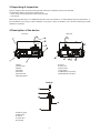
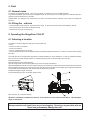
Version 1.1
StageFaze 1500 AT
Table of contents
1.Introduction...................................................................................................................... 3
2.Cautions ........................................................................................................................... 3
3.Unpacking & Inspection.................................................................................................. 4
4.Description of the device................................................................................................ 4
5. Fluid ................................................................................................................................. 5
5.1 General notes ...........................................................................................................................................5
5.2 Filling the fluid tank....................................................................................................................................5
6. Operatting the StageFaze 1500 AT ............................................................................... 5
6.1 Selecting a location ...................................................................................................................................5
6.2 Putting into operation ................................................................................................................................6
6.2 Switching the StageFaze 1500 AT off.......................................................................................................6
7. Cleaning,care and maintenance ................................................................................... 9
8. Troubleshooting ............................................................................................................. 9
9. Specifications ................................................................................................................. 9
2
1.Introduction
Thank you for choosing an ROBE StageFaze 1500 AT. You now own a rugged and powerful state-of-the-art machine. Prior to use,
we suggest that you carefully read all of the instructions. By following the suggestions found in this user manual, you can look forward
to the reliable and satisfactory performance of your ROBE Stage Faze 1500 AT machine for years to come.
Please follow these operation, safety and maintenance instructions to ensure a long and safe life for your fog machine.
2.Cautions
Risk of electric shock. Disconnect the appliance from the electric supply before
removing the cover.
Note: there are no user serviceable parts inside.
Danger of Electric Shock
Keep this device dry.
For inside use only. Not designed for outside use.
Prior to use take care to determine that the unit is installed at the rated voltage.
Always unplug your ROBE Faze machine before filling its tank.
Keep fog machine upright.
Unplug the machine when not in use.
This machine is not water - or splash-proof. If moisture, water, or fog liquid gets inside the housing, immediately unplug
the unit and contact a service technician or your ROBE distributor before using it again.
No user serviceable parts inside. Refer to your ROBE distributor or other qualified service personnel.
Danger of Burns
For adult use only. Never leave the unit running unattended.
Never aim at persons directly and keep a minimum distance of 3 m to the nozzle.
Faze machine output area is very hot. Avoid coming within 60 cm of the output nozzle during operation.
Keep a minimum distance of 60 cm to all flammable, combustible objects and objects sensitive to heat.
Locate the Faze machine in a well-ventilated area. Never cover the unit's vents.
Never aim the output nozzle at open flames.
If the supply cord is damaged, it must be replaced by manufacturer or its service agent or similarly qualified personnel in
order to avoid a hazard.
Always allow your StageFaze 1500 AT to cool down before attempting to clean or service it.
Danger of Explosion
Never add flammable liquids of any kind (oil, gas, perfume) to the Faze liquid.
Use only original liquid recommended by ROBE distributor.
Spilled fluid or splashed fluid droplets can cause slip hazard.
Always make sure there is sufficient liquid in the Faze liquid tank. Operating this unit without liquid will cause damage
to the pump as well as over-heating of the heater.
If your ROBE Faze machine fails to work properly, discontinue use immediately. Drain all fog liquid from the tank, pack the
unit securely (preferably in the original packing material), and return it to your ROBE distributor for service.
Always drain tank before mailing or transporting this unit.
Never drink fog liquid. If it is ingested, call a doctor immediately. If fog liquid comes in contact with skin or eyes, rinse thoroughly with
water.
Pay attention to all warning labels and instructions printed on the exterior of
StageFaze 1500 AT
People with health problems or problems of therespiratory tract or with an inclination for allergies should avoid any contact with artificially-made fog.
3
3.Unpacking & Inspection
Open the shipping carton and verify that all equipment necessary to operate the system has arrived intact.
The StageFaze 1500 AT comes with the following items:
- 1 tank, lid with quick connector,silicon tube and air valve filter
- 1 user manual
Before beginning initial setup of your ROBE Faze machine, make sure that there is no evident damage caused by transportation. In
the event that the unit's housing or cable is damaged, do not plug it in and do not attempt to use it until after contacting your ROBE
distributor for assistance.
4.Description of the device
Front view
Rear view
1-Nozzle
2-Control panel
3-Handle
4-Fluid tank
5-Fluid tube
6-Fluid tube inlet
7-Mounting bracket
8- Tilt-lock
9- Power cord
10-Powe switch
11-Fuse holder
12- DMX IN/OUT (3-pin XLR)
13-DMX IN/OUT (5-pin XLR)
Tank lid
14-Brass coupling
15-Brass collar
16-Tank lid
17-Check valve
18-Fluid filter
4
5. Fluid
5.1 General notes
The ready-to-use StageFaze 1500 AT fluid for use in this device is available from your local ROBE distributor.
To guarantee trouble-free operation the special “StageFaze 1500 AT“ must be used. Use of other liquids will void the manufacturer‘s
warranty and can be dangerous to your health.
PLEASE NOTE: The vaporizer of the machine does not have to be cleaned! Cleaners, available on the market, can damage the
vaporizer!
5.2 Filling the fluid tank
– Unscrew the tank lid [16] of the tank [4] and remove the empty fluid tank from the tank housing of the StageFaze 1500 AT
– Fill the tank and place the full tank into the tank housing
– Screw the tank lid [16] up into the tank [4]
6. Operating the StageFaze 1500 AT
6.1 Selecting a location
The location in which the StageFaze 1500 AT is to be operated must
– be dry,
– be free from dusty or polluted air,
– be free from vibrations,
– be a non-flammable place or surrounding,
– be well-ventilated with Faze-free air keeping the ambient operating temperature between 10° C and 40° C and the relative humidity
below 80%.
This model includes a mounting bracket designed for overhead installation, it may be installed at floor level or suspended overhead.
If the unit is to be mounted using the bracket, it is important that the fog does not shoot directly at any one's face.
Overhead installation:
1)Bolt the clamp (C) to the omega holder (D).
2)Fix the omega holder on the mounting bracket (A) by means of 2 quick-lock fasteners.
3)Mount the StageFaze 1500 AT on a truss using the clamp (C).For overhead use, always install a safety rope that can hold at least 10
times the weight of the device. You must only use safety ropes with screw-on carabines. Pull the safety rope through the two apertures
on the bottom side of the StageFaze 1500 AT base and over the trussing system etc.
4)Adjust the tilt angle using the tilt-lock (B).
5)Use the adjusting knob (E) to set the faze shutter position .
Note: The clamp (C) is not part of delivery.
Whatever installation method you choose, do not allow the unit to have more than a +30/-30 degree
angle of inclination.
Important!
Always monitor tank liquid level as you are fogging. Running a fog machine with no
liquid can permanently damage the unit.
5
6.2 Putting into operation
Warning: Never connect the StageFaze 1500 AT to a dimmer or switchpack! This may destroy the machine.
Connect the power plug to the mains supply. Make sure the correct voltage is selected.Switch on the power switch (10).
A P and two figures appear on the LED display e.g.:
After 60 Seconds, the StageFaze 1500 AT is heated up. Press the Enter-button once to start the Faze process. The green Active-LED will be lit. After
a short delay the machine begins to Faze.
After 30 Seconds the display will go dark. To re-activate it, press one of the buttons on the display.
6.2 Switching the StageFaze 1500 AT off
Press the Mode-button till „OFF” appears on the display and press the Enter-button.
On the display a small moving red line will appear.
Switch off the power switch (10)
When you switch off the DMX signal, the fan will be switched off automatically after 15 seconds.
Note:
Please make sure that the StageFaze 1500 AT will not be switched off too early to allow the fan to run until the device has cooled down. This will
ensure that no fluid remains in the vaporizer to come out as droplets when the device is switched on next time.
6.3 Control Choices
Profile/Timer-LED,red
LED display
Active-LED,green
DMX-LED,yellow
Mode-button Up-button Down-button Enter-button
Fig.1: Adjusting the pump output
Fig.2: Adjusting the fan output
Fig.4: Changing to the Profile-Mode
Fig.5: Switching the device Off
Fig.3: Adjusting the DMX start address
You may control the StageFaze 1500 AT externally through the 3-pin or 5-pin XLR sockets .
Please note: You can‘t hold down the Mode-button for scrolling through the Menu. The Mode-button has to be pressed only momentarily. If the Mode-button is pressed more than two seconds, the machine will change into the Timer-Mode.
An outstanding feature is the adjustable output of the StageFaze 1500 AT. The pump and the fan can be easily and separately adjusted and regulated
in 99 steps via buttons.Any desired effect can be achieved in steps of 1%: from the finest mist to a thick Faze, similar to fog. To achieve the thickest
effect the pump must run at 99%, the fan at 1%. The finest Faze can be achieved with lower pump and higher fan settings. The data can be readjusted
whenever you want to.
6
6.4 Operating via DMX 512
Connecting the StageFaze 1500 AT to a DMX desk, use the 3XLR sockets [12], at the rear side of the fixture. As soon as the machine receives a
correct DMX signal, the yellow DMX LED will be lit.
Please note: The StageFaze 1500 AT uses two channels on your DMX desk! First Channel = Pump, second Channel =Fan
Adjusting the DMX start address
1) Press the Mode-button [14] at the control panel until three figures appear on the LED-display [17] (see Fig. 3).
2) Adjust the required start address by pressing the Up- or Down-button [15].
3) Save the start address by pressing the Enter-button [16] once. The start address will now also be saved when you disconnect the machine from
the mains supply.
Adjusting the pump and fan output
If you run the machine via a DMX desk you can adjust the pump and the fan directly from the desk from 1 to 99%.
The adjusted channel controls the pump, the following one controls the fan.
6.5 Stand alone
The StageFaze 1500 AT can be used in the Stand alone mode. In this mode all data for the pump and the fan must be adjusted directly at the machine.
Adjusting the pump and fan output
1) Press the Mode-button at the control panel until a P and two figures appear on the LED-display (see Fig. 1).
2) Adjust the desired data (1 - 99%) by pressing the Up- or Down-button .
3) Press the Mode-button again until an F and two figures appear on the display (see Fig. 2).
4) With the Up- or Down-button the fan data can now be adjusted.
5) Press the Enter-button once to start the machine. The green Active-LED will be lit.
6.6 Faze-Density Control System(HDCS)
Fig. 6: Adjusting the Pause (Pre-Runtime)
Fig. 7: Adjusting the pump
Fig. 8: Start the profile
Fig. 9: Quit the profile
With the HDCS, an individual profile for a show can be programmed. Two Levels (Level A and B) with different pump and fan values and different
run-times can be programmed (Level A = settings 2, 3, 4 / Level B = settings 5, 6, 7). Also a pre-runtime can be programmed in (setting 1) which tells
the machine when it should start to run.
For example: The machine shall start to run after 30 Minutes (setting 1). Then the stage should be filled with Faze within 10 Minutes. Therefore a high
pump and fan output should be adjusted and a time of 10 Minutes (setting 2, 3, 4).
After 10 Minutes high output, pump and fan shall go down automatically to a lower step and fill the stage with Faze for another hour (setting 5, 6, 7).
See diagram on page 8 also.
The following Profile settings can be adjusted:
1. Pause (Pre-Runtime) 0 - 99 min
2. Pump (Level A) 1 - 99 %
3. Fan (Level A) 1 - 99 %
4. Run-Time (Level A) 0 - 99 min
5. Pump (Level B) 1 - 99 %
6. Fan (Level B) 1 - 99 %
7. Run-Time (Level B) 0 - 99 min
Using the profile
1) Press the Mode button repeatedly until „Pro“ appears on the display (seeFig. 4).
7
2) Press the Enter button once to switch to the HDCS Menu. The red Timer/Profile-LED will be lit.
3) Adjust settings 1 to 7 according to the chart below, using the Up/Down buttons and pressing the Mode button to switch between
the settings.
These settings are stored in non-volatile memory. You don‘t have to run the Profile or press the Enter button in order to „save“ the
settings. All settings can be changed as described at any time.
4) To start the Profile with the adjusted values, press the Mode button until „run“ appears on the display (Fig. 8), then press the Enter
button.
The Timer/Profile-LED flashes, indicating that the Profile is running. The green Active-LED lights as soon as the adjusted Pause (Pre-Runtime) has passed and level A has started.
5) To leave the HDCS menu or quit the Profile, first press the Mode button until „ESC“ appears on the display (Fig. 9). Then press the
Enter button once to return to the main menu.
6.7 Operating the internal Timer
Fig.10: Adjusting the Pause (Wait-time)
Fig.11: Adjusting the faze time
Fig.12:Adjusting the fan
Fig.13:Adjusting the pump
Fig. 14: Quit the Timer-Mode
With the internal timer, the Faze time and wait time can be adjusted in minutes (0.1 - 99), the pump and fan output can be adjusted in per cent (0
- 99).
To start the Timer-Mode, press and hold the Mode button for more than 2 seconds. The red Timer/Profile-LED ] will blink as soon as the machine has
switched to the Timer-Mode. As long as the timer is in operation, the red Timer/Profile-LED blinks.
The adjusting of the output, Faze time or wait time is the same as in the Standard-Menu. This means you have to press the Mode button repeatedly
until you reach the required function.
With the Up/Down buttons you can adjust the required functions, then press the Enter button to start the timer. Please note that P and F control Pump
and Fan, whereas P. and F. control Pause time and Faze (Fog) time (Figs. 10 - 13).
The timer cycle starts with the time shown on the display when you press the Enter button (i. e. P.xx = Starts with wait time, F.xx = Starts with Faze
time). The timer cycle will not start if you press the Enter button while the pump or fan output setting is shown on the display.
You can switch back to the Standard-Menu by pressing the Mode button for more than 2 seconds or by pressing the Mode button repeatedly until
„ESC“ shows on the display and then press the Enter button once.
8
Auto start
If the timer is in operation and you disconnect the machine from the mains cable, the StageFaze 1500 AT will re-start in the Timer-Mode as soon
as it‘s reconnected to the mains. To stop this press the Mode-button for more than 2 seconds or by switching to „ESC“ in the Timer-Mode and then
press the Enter-button.
7. Cleaning,care and maintenance
Remove the filter, which protects the fan against dust and dirt, from time to time and clean it.
– After several hours of operation, some droplets of condensation will have formed at the nozzle. That is normal and not a malfunction.
Please note: Remove fluid droplets at the nozzle only when the machine has completely cooled off. During operation the nozzle gets very hot!
– Do not let the StageFaze 1500 AT run without any fluid as the pump will run dry.
– Check the state of the fluid filter [18] from time to time and clean or replace it when necessary.
– PLEASE NOTE: The vaporizer of the machine does not have to be cleaned! Cleaners, available on the market, can damage the vaporizer!
8. Troubleshooting
Trouble: The pump runs, but little or no Faze is produced.
Cause: The pump sucks no or too little fluid.
- Check whether the tank is empty
- Check whether the brass collar is properly connected with the brass coupling
- Check whether the fluid filter in the tank is clogged
- Check whether the fluid tube is twisted or defective
Trouble: The yellow LED at the machine does not light up (only when running via DMX)
Cause: Connection from the machine to the desk is faulty.
- Check whether the plug is plugged in correctly
- Check whether the cable is defective
- Check whether the DMX start address is adjusted correctly
Trouble: During operation the StageFaze 1500 AT fails to work for a long time
Cause: The overtemperature protection device is activated.
- Check whether the fan is clogged
Trouble: E-4 appears on the LED display:
Cause: The machine is getting too hot. The heating switches off and the machine cools down.
Solution: Disconnect the machine from the mains supply for a moment and then re-connect it.
Trouble: E-8 appears on the LED display:
Solution: The vaporizer is clogged.
Cause: Please send the machine to your local dealer.
Trouble: E-1 appears on the LED display:
Solution: Please send the machine to your local dealer.
9. Specifications
Power requirement: 1500 Watt
Voltage: 230 V/ 50 Hz or
Fuse: 8A at 230 V
Warm up time: approx. 60 Seconds
Fluid tank capacity: 2 liters
Integrated Fan: > 6000 l/min.
Faze density: variable
Control: DMX 512
Weight (without liquid):12 kg
Max. tilt inclination:+30°/-30°
Dimensions:
Accessories: Omega holder (No.99010420).............1pcs
Specifications are subject to change without notice.
9