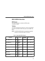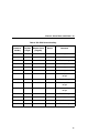
1
RFID Labeling Reference Manual
SL5000r MP and MP2
RFID Smart Label Printers
™
SL5000 r MP and MP2
RFID Smart Label Printers
RFID Labeling Reference Manual
Printronix makes no representations or warranties of any kind regarding this material, including, but not limited
to, implied warranties of merchantability and fitness for a particular purpose. Printronix shall not be held
responsible for errors contained herein or any omissions from this material or for any damages, whether
direct, indirect, incidental or consequential, in connection with the furnishing, distribution, performance or use
of this material. The information in this manual is subject to change without notice.
This document contains proprietary information protected by copyright. No part of this document may be
reproduced, copied, translated or incorporated in any other material in any form or by any means, whether
manual, graphic, electronic, mechanical or otherwise, without the prior written consent of Printronix.
COPYRIGHT © 2005, 2006 PRINTRONIX, INC. All rights reserved.
Trademark Acknowledgements
Alien and Alien Technology are registered trademarks of Alien Technology Corporation.
Avery is a trademark of Avery Dennison Corporation.
Impinj is a registered trademark of Impinj, Inc.
Manhattan Associates is a registered trademark of Manhattan Associates, Inc.
Matrics is a registered trademark of Matrics, Inc.
Omron is a trademark of OMRON Corporation.
Printronix, PGL, and PrintNet are registered trademarks of Printronix, Inc.
Rafsec is a registered trademark of Rafsec.
SATO is a registered trademark of SATO America, Inc.
SL5000r is a trademark of Printronix, Inc.
Symbol is a registered trademark of Symbol.
TI is a trademark of Texas Instruments Incorporated.
Uniform Code Council, Inc. is a registered trademark of Uniform Code Council, Inc.
Zebra and ZPL are trademarks of Zebra Technologies Corporation.
Zuma is a trademark of Impinj, Inc.
Table of Contents
1 RFID Smart Label Application
And Reference Notes ................................ 9
Overview............................................................................... 9
What To Expect When Running Your RFID Application..... 11
Factors Affecting Smart Label Performance ................ 11
Overstruck Smart Labels.............................................. 11
Smart Label Characteristics ......................................... 12
Transitioning From UCC/GTIN Applications Using
Printronix Software Migration Tools (SMT)......................... 14
How Printronix Makes It Easy ...................................... 14
How It Works ................................................................ 14
Hardware/Infrastructure Considerations ............................. 15
Contact Information ............................................................ 16
Printronix Professional Services .................................. 16
How To Order More Smart Labels ............................... 16
Printronix Customer Support Center ............................ 16
Corporate Offices ......................................................... 17
Useful Industry Web Links ........................................... 18
2 Smart Label Development....................... 19
Overview............................................................................. 19
RFID CONTROL Menu....................................................... 20
RFID CONTROL Menu Items ...................................... 23
Admin User Menu Items............................................... 30
Requesting An RFID Report ............................................... 34
RFID PGL Commands........................................................ 35
RFWTAG...................................................................... 35
RFRTAG ...................................................................... 45
VERIFY ........................................................................ 48
Write Tag...................................................................... 52
Read Tag ..................................................................... 54
5
Table of Contents
RFID PPI/ZGL Commands ..................................................55
Read Tag ......................................................................55
Write Tag ......................................................................56
Write or Read RFID Format ..........................................57
Calibrate RFID Transponder Position ...........................58
Define EPC Data Structure ...........................................58
Enable RFID Motion......................................................59
Specify RFID Retries for a Block...................................59
RFID Setup ...................................................................59
Set RFID Tag Password ...............................................60
Host Verification ............................................................61
PPI/ZGL EPC Programming Examples.........................61
RFID PPI/STGL Commands................................................63
Return Status Port ...............................................................64
Software Migration Tools (SMT)..........................................65
Tools List.......................................................................65
Selecting The Tools ......................................................67
Error Messages ...................................................................68
Troubleshooting...................................................................70
3 MP2 RFID................................................ 71
New Coupler System...........................................................71
Adjusting The Coupler Position.....................................72
64 Bit And 96 Bit EPC Data Formats...................................73
Class 1 Gen 1 ...............................................................73
Gen 2 ............................................................................73
Class 0+, Class Zuma, and Class 1.19.........................73
Moving From 64 Bit Tags To 96 Bit Tags ............................76
When 64 Bit Data Is Sent To A 96 Bit Tag: PGL...........76
When 64 Bit Data Is Sent To A 96 Bit Tag: ZGL...........77
PGL .....................................................................................78
Multiple Read/Write Commands On One Label ............78
The VERIFY Command is not RFID Specific................79
6
Table of Contents
Splitting the EPC................................................................. 79
Customer Scenario ...................................................... 79
Using The Advanced RFID Calibration............................... 81
Tag Profiler................................................................... 81
Custom Tag Configurator ............................................. 82
Auto Inlay Locater ........................................................ 82
7
Table of Contents
8
1
RFID Smart Label
Application And
Reference Notes
Overview
NOTE: For the latest version of this reference manual, visit the
Services & Support page at www.printronix.com.
This manual covers the following products:
•
•
•
Printronix SL5000r DK Smart Label Developer's Kit
•
Printronix SL5000r MP2 Multi-protocol RFID printer, supporting
Class 0/0+, Class 1, Class 1.19 RFID, Class Gen 2, and
Class Zuma™ RFID tags and labels
Printronix SL5000r DK2 Smart Label Developer's Kit
Printronix SL5000r MP Multi-protocol RFID printer, supporting
Class 0/0+, Class 1, Class 1.19 RFID, Class Gen 2, and
Class Zuma™ RFID tags and labels
9
Chapter 1 Overview
The Printronix SL5000r DK/DK2 Smart Label Developer’s Kit
contains:
•
•
SL5000r MP/MP2 multiprotocol RFID printer
•
Software Migration Tools that permit the seamless encoding of
smart labels
•
Media starter kit (100 4 inch x 6 inch standard labels, 50 m
8500 thermal premium wax resin ribbon, and a printhead
cleaning pen)
•
•
•
1000 Class 1 RFID smart labels
•
•
•
•
Programming manuals (CD)
Integrated RFID UHF encoder supporting Class 0/0+, Class 1,
Class 1.19, Class Gen 2, and Class Zuma RFID tags and
labels
One 625 m thermal premium wax ribbon
Network interface card, which includes Printronix’s PrintNet®
Enterprise, a remote network printer management software
application.
RFID Labeling Reference Manual (this manual)
Application and reference notes (this chapter)
Technical support
The intent of the kit is to provide a complete environment for the
printing and encoding of RFID smart labels right out of the box.
Printronix has specifically designed this kit to help you fast track
your RFID printer application through the use of a suite of Software
Migration Tools (SMT).
10
Factors Affecting Smart Label Performance
What To Expect When Running Your RFID Application
Factors Affecting Smart Label Performance
Smart labels are based on an EEPROM technology that requires
some time to be programmed. You may notice this minor pause
between labels. This time is necessary to better ensure consistent
quality and improved reliability.
When dealing with smart labels, it is possible that an occasional
RFID tag may need to be written and verified more than once (retry)
before being considered acceptable. In this event each retry time
will be added to the inter-label pause.
Static electricity can damage the smart labels. Open the media
cover of the printer and touch an unpainted metal part of the printer
before you handle smart labels. This will discharge any static
electricity that may have built up on your hands.
Overstruck Smart Labels
If an RFID tag within a smart label is deemed unacceptable after
execution of the defined number of retries, what occurs next
depends upon the Error Handling setting. See “Error Handling” on
page 27.
11
Chapter 1 What To Expect When Running Your RFID Application
Smart Label Characteristics
IMPORTANT
Purchase additional smart labels directly from Printronix to
assure the highest level of performance and reliability. See
“How To Order More Smart Labels” on page 16.
Supported Tag Types
Printronix RFID SL5000 MP and MP2 printers support a number of
RFID protocols and coupler configurations.
For a list of Certified RFID Smart Labels available from Printronix,
and a complete list of tag types supported by Printronix RFID
SL5000 MP and MP2 printers:
1. Go to www.printronix.com and select your Country/Language
of choice.
2. Under SOLUTION OFFERINGS, click RFID Printers.
3. Under RFID Smart Labels, click View Series.
a. For a list of Certified RFID Smart Labels available from
Printronix, click Certified RFID Labels.
b. For a complete list of supported RFID tag types,
click Supported RFID Tags.
These web pages will be updated regularly to include newly
supported RFID tag types and newly Certified RFID Smart Labels
available from Printronix.
Currently supported smart labels have the following characteristics:
General Tag Type
•
12
UHF 869/915 MHz radio frequency
Smart Label Characteristics
Technology Tag Class
•
•
•
•
EPC Class 0 tags – 64 data bits Read Only
EPC Class 0 tags – 96 data bits Read Only
EPC Class 0+ tags – 64 data bits Read/Write
EPC Class 0+ tags – 96 data bits Read/Write
NOTE: For EPC Class 0+, Class 1.19, and Class Zuma tags, the
AWID multi-protocol reader used by Printronix enforces the
EPC format in the following manner:
•
•
•
•
•
•
•
For 96–bit data, the two most significant bits must be 0.
For 64–bit data, the two most significant bits must be 1.
EPC Class 1 tags – 64 data bits Read/Write
EPC Class 1 tags – 96 data bits Read/Write
EPC Class 1.19 tags – 96 data bits Read/Write
EPC Class Gen 2 tags – 96 data bits Read/Write
Impinj® Zuma tags – 96 data bits Read/Write
Label Size
4 x 2, 4 x 4, 4 x 6, 4 x 8 inch label stock
13
Chapter 1 Transitioning From UCC/GTIN Applications Using Printronix Soft-
Transitioning From UCC/GTIN Applications Using
Printronix Software Migration Tools (SMT)
It is likely that your software is already set up to create bar codes.
You may have also spent a lot of time creating compliance label
templates & integrating them into your system. The Smart Label
Developer’s Kit Software Migration Tools will allow you to
effortlessly transition from printing compliance labels to smart
labels.
How Printronix Makes It Easy
If you are printing bar codes now, you can print smart labels — no
change to your host datastream or existing compliance templates is
required.
How It Works
A set of Software Migration Tools has been created to intercept the
bar code data in the host datastream and copy the data to a smart
label RFID tag according to a set of rules. Each tool has been
designed for a specific end-use application. By simply selecting the
desired Software Migration Tool from the printer’s control panel,
you automatically enable the printer to create an RFID smart label
from your existing software application even if the software does
not have the functionality to program RFID tags. The tools include:
14
•
GTIN: Copies the Global Trade Identification Number (GTIN)
bar code data for case and pallet labels onto the smart label’s
RFID tag.
•
EAN-8, EAN13, UPCA, and UCC128: These tools copy the
data from their respective bar code symbologies to a smart
label’s RFID tag. This enables the achievement of supply-chain
efficiencies with RFID-ready trading partners while at the same
time remaining compatible with those who are not.
How It Works
•
EPC: This tool allows EPC data to be directly encoded into the
smart label’s RFID tag. Simply have your existing software
application write the desired EPC number to a Code 3 of 9
barcode. The printer will then write the EPC data to the RFID
tag without printing the bar code.
The existing toolset will meet the needs of many RFID early
adopters. If you have a requirement for a Software Migration Tool
not included in this kit, feel free to contact Printronix.
To select and use the tools, see “Software Migration Tools (SMT)”
on page 65.
Hardware/Infrastructure Considerations
Once your smart labels have been applied to their target container
or pallet you will need external readers to track them through your
supply chain. Such readers are typically networked devices that are
deployed at key points in the warehouse or distribution center to
track incoming and outgoing packages. The readers are managed
through a server for gathering and filtering all the RFID information.
Readers may have multiple couplers to maximize read range and
reliability.
The readers you purchase must be compatible with the smart
labels programmed by the printer. Specifically, they should be EPC
Class 0, Class 0+, Class 1, Class 1.19, Class Gen 2, and Class
Zuma compliant. Handheld readers with integrated couplers can be
purchased from AWID (www.awid.com).
The data that are gathered by the reader servers must be managed
for tracking and archiving purposes. Software applications that
perform these tasks are available from companies such as
Manhattan Associates® (www.manh.com).
15
Chapter 1 Contact Information
Contact Information
Printronix Professional Services
Printronix can partner with you on your RFID pilot project to make
your existing software applications RFID/smart label capable. We
specialize in smart label print and apply configuration and
integration, RFID pilot implementation, and transition from RFID
pilots to full production rollouts.
Call the Printronix Customer Support Center at (714) 368-2686 and
ask for Professional Services Support.
How To Order More Smart Labels
Contact the Printronix Supplies Department for genuine Printronix
supplies.
Americas
(800) 733-1900
Europe, Middle East, and Africa
(33) 1 46 25 1900
Asia Pacific
(65) 6548 4116 or
(65) 6548 4182
http://www.printronix.com/supplies-parts.aspx
Printronix Customer Support Center
IMPORTANT
16
Please have the following information available prior to calling
the Printronix Customer Support Center:
•
•
•
Model number
•
Configuration printout (see “Printing A Configuration” in the
Quick Setup Guide)
•
Is the problem with a new install or an existing printer?
Serial number (located on the back of the printer)
Installed options (i.e., interface and host type if applicable to the
problem)
Corporate Offices
•
•
Description of the problem (be specific)
Good and bad samples that clearly show the problem (faxing of
these samples may be required)
Americas
(714) 368-2686
Europe, Middle East, and Africa
(31) 24 6489 311
Asia Pacific
(65) 6548 4114
http://www.printronix.com/support.aspx
Corporate Offices
Printronix, Inc.
14600 Myford Road
P.O. Box 19559
Irvine, CA 92623-9559
Phone: (714) 368-2300
Fax: (714) 368-2600
Printronix, Inc.
Nederland BV
P.O. Box 163, Nieuweweg 283
NL-6600 Ad Wijchen
The Netherlands
Phone: (31) 24 6489489
Fax: (31) 24 6489499
Printronix Schweiz GmbH
42 Changi South Street 1
Changi South Industrial Estate
Singapore 486763
Phone: (65) 6542 0110
Fax: (65) 6546 1588
Visit the Printronix web site at www.printronix.com
17
Chapter 1 Contact Information
Useful Industry Web Links
Printronix, Inc.
www.printronix.com
Alien Technology® Corporation
www.alientechnology.com
Applied Wireless Identifications Group, Inc.
www.awid.com
EPCglobal, Inc.
www.epcglobalinc.org
RFID Journal
www.rfidjournal.com
Uniform Code Council, Inc.®
www.uc-council.org
18
2
Smart Label
Development
Overview
This chapter describes how to use the RFID encoder. The RFID
encoder is designed to be transparent to the printer operation. It
provides the capability of programming smart labels (with
embedded RFID tags) while printing the label format. The smart
labels are provided with the printer or purchased separately from
Printronix.
There are several ways to program RFID tags in smart labels:
•
Use the Software Migration Tools (SMT) to enable the printer to
automatically create RFID commands from your existing bar
code commands. These tools are described on page 65.
•
Incorporate RFID commands into new or existing Printronix
PGL® programs. Command details start on page 35.
•
Incorporate RFID commands into new or existing ZPL™
programs. By selecting the Printronix PPI/ZGL emulation you
can seamlessly upgrade from Zebra™ printers. Command
details start on page 55.
•
Incorporate RFID commands into new or existing SATO®
printer language programs. By selecting the Printronix
PPI/STGL emulation you can seamlessly upgrade from SATO
printers. Command details start on page 63.
19
Chapter 2 RFID CONTROL Menu
RFID CONTROL Menu
RFID CONTROL
RFID Reader
Tag Type
Enable*
Disable
Alien Squig 64 1
Alien M-TAG 64 1
Alien Squig 96*
Alien M-TAG 96 1
RAF Omni 313 64 1 RAF Omni 432 96 1 Matrics1020 64 1 Matrics1020 96 1
Matrics2020 64 1
Matrics2020 96 1
EPC Gen2 96 1
Omron Wave 1
Avery AD410 IN 1
RAFUCode 450 96
Rafsec 478 1
Avery BL 1, 2
ImpZ Prop 96 1
X-Ident PH58 96
Alien Itag 96 1, 2
Alien SupS 96 1
TI Dallas G2
Avery AD220 G2 1
Imp Banjo G2 1, 3
Imp Prop G2 1, 3
Alien Squig G2
RAF Square G2 1, 3
RAF Short G2 1, 3
X-Ident PH60 96
ImpZ Triflex 96 1, 3
Flex Wing 1, 2
Avery AD810 96 1, 3
Avery AD210 1
KSW Excal G2 1, 3
Flex Wing G2 1
Omron Loop 1
Sym 4T G2 1, 3
RAF Frog G2 1, 3 Alien 9334-02 1, 3 Sym Trident G2 1, 3 Alien 9460 Omni 3
Omron Wave G2 3
EPC G2 Phil3 3
KSW Templar G2 1, 3
EPC G2 Phil2 3
EPC G2 Phil4 3
Error Handling
Overstrike*
None
Label Retry
10*
1 to 10
Max Retry Error
Enable*
Disable
Stop
Notes:
* = Default.
1
Appears only if an AWID 915 encoder
(USA/Canada) is installed.
2
Appears only on six inch printers.
3
Appears only on MP2 RFID printers.
(cont. on next page)
20
EPC G2 Phil1 3
RFID CONTROL
(cont. from previous page)
Tag Write Cnt 1
Failed Tag Cnt 1
Tag Void Cnt 1
Tag Read Cnt 1
Clear Tag Stat
Read Tag
Read Tag&Eject
PreErase Class 0+ 2
Enable*
Disable
Auto Retry
2*
1 to 9
Precheck Tags
Disable*
Enable
Overstrike Style
Grid*
Custom Tag
Duplicate*
F/W-Version 1
(cont. on next page)
Error Type Msg
Disable
Enable
Notes:
* = Default.
Italicized items appear only when Admin User is set
to Enable (in the PRINTER CONTROL menu).
1
Display item only.
2
Appears only if Tag Type is set to Matrics2020 64
or Matrics2020 96.
21
Chapter 2 RFID CONTROL Menu
RFID CONTROL
(cont. from previous page)
Custom Write Pwr
6*
1 to 20
Custom Read Pwr
5*
1 to 20
Custom Tag Len
12*
8 to 32
Custom Tag Class
Class 1*
Gen 2
Custom Rd Tries 1
Infinite*
1 to 10
Custom Wr Tries 1
9*
1 to 10
Cust Early Write 1
0.00 inches*
Class 0
Class 0+
Class 1.19
Class Zuma
0.00 to 99.00 inches
Custom Run Cal 1
Custom Tag Pos 1
0.0 inches*
–1.5 to 5.0 inches
Custom Start Pos 1
0.0 inches*
0.0 to 5.0 inches
Custom Scan Len 1
3.0 inches*
0.0 to 5.0 inches
Custom Min Pwr 1
1*
1 to 20
Custom Max Pwr 1
20*
1 to 20
EPC Mgr Report
Disable*
Enable
Non-RFID Warning
Disable*
Enable
Notes:
* = Default.
Italicized items appear only when Admin
User is set to Enable (in the PRINTER
CONTROL menu).
1
22
Appears only on MP2 RFID printers.
RFID CONTROL Menu Items
RFID CONTROL Menu Items
RFID Reader
This menu item enables or disables the RFID encoder.
The default is Enable.
Tag Type
This menu item selects the tag type in use. Table 1 lists supported
tags types in alphabetical order. Other types may be added in the
future.
NOTE: The “RFID CONTROL Menu” on page 20 lists supported
tags types in the order they appear in the menu.
Table 1. Supported RFID Tag Types
Tag Name
Bits
Protocol
Custom
Tag Class
Menu Selection
Alien® 9334 (2 x 2)
96
Class 1,
Gen 1
Class 1
Alien 9334-02
Alien 9460 Omni
96
Class 1,
Gen 2
Gen 2
Alien 9460 Omni
Alien Gen 2 Squiggle
96
Class 1,
Gen 2
Gen 2
Alien Squig G2
Alien I-Tag
96
Class 1,
Gen 1
Class 1
Alien Itag 96
Alien M-Tag
64
Class 1,
Gen 1
Class 1
Alien M-TAG 64
Alien M-Tag
96
Class 1,
Gen 1
Class 1
Alien M-TAG 96
Alien Squiggle
64
Class 1,
Gen 1
Class 1
Alien Squig 64
23
Chapter 2 RFID CONTROL Menu
Table 1. Supported RFID Tag Types
Tag Name
Bits
Protocol
Custom
Tag Class
Menu Selection
Alien Squiggle
96
Class 1,
Gen 1
Class 1
Alien Squig 96
Alien Squiggle 2
(aka Super Squiggle)
96
Class 1,
Gen 1
Class 1
Alien SupS 96
Avery™ AD-210 (aka Strip)
96
Class 1,
Gen 1
Class 1
Avery AD210
Avery AD-220
(aka Runway)
96
Class 1,
Gen 2
Gen 2
Avery AD220 G2
Avery AD-410 (aka IN)
96
Class 1,
Gen 1
Class 1
Avery AD410 IN
Avery AD-610 (aka BL)
96
Class 1,
Gen 1
Class 1
Avery BL
Avery AD-620 (aka Triflex)
96
Class Zuma
Generic Philips
(coupler yellow)
96
Generic Philips
(coupler orange)
Class Zuma
ImpZ Triflex 96
Class 1,
Gen 2
Gen 2
EPC G2 Phil1
96
Class 1,
Gen 2
Gen 2
EPC G2 Phil2
Generic Philips
(coupler red)
96
Class 1,
Gen 2
Gen 2
EPC G2 Phil3
Generic Philips
(coupler blue)
96
Class 1,
Gen 2
Gen 2
EPC G2 Phil4
Impinj Gen 2 Banjo
96
Class 1,
Gen 2
Gen 2
Imp Banjo G2
Impinj Propeller
96
Class Zuma
Class Zuma
ImpZ Prop 96
Impinj Gen 2 Propeller
96
Class 1,
Gen 2
Gen 2
Imp Prop G2
24
RFID CONTROL Menu Items
Table 1. Supported RFID Tag Types
Tag Name
Bits
Protocol
Custom
Tag Class
Menu Selection
KSW Gen 2 Excalibur
96
Class 1,
Gen 2
Gen 2
KSW Excal G2
KSW Gen 2 Templar
96
Class 1,
Gen 2
Gen 2
KSW Templar G2
Omron™ Loop
96
Class 1,
Gen 1
Class 1
Omron Loop
Omron Wave
96
Class 1,
Gen 1
Class 1
Omron Wave
Omron Gen 2 Wave
96
Class 1,
Gen 2
Gen 2
Omron Wave G2
Rafsec® 313
64
Class 1,
Gen 1
Class 1
RAF Omni 313 64
Rafsec 432
96
Class 1,
Gen 1
Class 1
RAF Omni 432 96
Rafsec 450
96
Class 1.19
Class 1.19
RAFUCode 450 96
Rafsec 478
96
Class 1,
Gen 1
Class 1
Rafsec Gen 2 Frog
(3000790)
96
Class 1,
Gen 2
Gen 2
RAF Frog G2
Rafsec Short Dipole
(OneTenna)
96
Class 1,
Gen 2
Gen 2
RAF Short G2
Rafsec Square Dipole
(OneTenna)
96
Class 1,
Gen 2
Gen 2
RAF Square G2
RF IDentics Flex Wing
96
Class Zuma
RF IDentics Gen 2
Flex Wing
96
Class 1,
Gen 2
Class Zuma
Gen 2
Rafsec 478
Flex Wing
Flex Wing G2
25
Chapter 2 RFID CONTROL Menu
Table 1. Supported RFID Tag Types
Bits
Symbol® Class 0 Read-Only
(aka Matrics® X1020)
64
Class 0
Class 0
Matrics1020 64
Symbol Class 0 Read-Only
(aka Matrics X1020)
96
Class 0
Class 0
Matrics1020 96
Symbol Class 0+
(aka Matrics X2020)
64
Class 0+
Class 0+
Matrics2020 64
Symbol Class 0+ 4T Glacier
(aka Matrics X2020)
96
Class 0+
Class 0+
Matrics2020 96
Symbol Gen 2 Four T
96
Class 1,
Gen 2
Gen 2
Sym 4T G2
Symbol Gen 2 Trident
96
Class 1,
Gen 2
Gen 2
Sym Trident G2
TI™ Gen 2 Dallas
96
Class 1,
Gen 2
Gen 2
TI Dallas G2
X-ident PH 58
96
Class 1.19
Class 1.19
X-Ident PH58 96
X-ident PH 60
96
Class 1.19
Class 1.19
X-Ident PH60 96
26
Protocol
Custom
Tag Class
Tag Name
Menu Selection
RFID CONTROL Menu Items
Error Handling
This menu item selects the error handling mode for RFID failures.
The default is Overstrike.
In Overstrike mode, each failed label prints with the Overstrike
pattern and the form retries on a new label until the Label Retry
count is exhausted. Whether or not an error message will display or
the failed label will reprint depends upon the Max Retry Error
setting.
In None mode, no specific action is taken when a tag fails to be
programmed.
In Stop mode, when a tag fails to be programmed, the printer will
halt and display the error message “RFID Error: Check Media.” The
label is discarded and reprinting of the label (if desired) must be
initiated from the host. When the error is cleared, the label with the
failed tag moves forward until the next label is in position to be
printed.
Label Retry
NOTE: Label Retry only applies when the Error Handling mode is
set to Overstrike.
This menu item selects the number of label retries that the RFID
encoder will attempt before declaring a fault. This may indicate a
problem with the RFID encoder, the coupler assembly, the printer
setup, or the label stock. The default is 10.
Max Retry Error
This menu item enables or disables Max Retry Error. If it is set to
Disable, errors are not declared and the print content for the current
label is discarded. The default is Enable.
Tag Write Cnt
This menu item displays on the control panel’s LCD the number of
tags attempted to be written since the last Clear Tag Stat operation
has been initiated. (See “Clear Tag Stat” below.)
27
Chapter 2 RFID CONTROL Menu
Failed Tag Cnt
This menu item displays on the control panel’s LCD the number of
failed tag write attempts since the last Clear Tag Stat operation has
been initiated. (See “Clear Tag Stat” below.)
Tag Void Cnt
This menu item always displays 0 unless the RFID encoder is used
with an attached online data validator. When used with a validator,
Tag Void Cnt represents how many valid RFID tags were
overstruck due to bad bar code scanning. Refer to the Online Data
Validator User’s Manual.
Tag Read Cnt
This menu item displays the number of tags read since the last
Clear Tag Stat (below).
Clear Tag Stat
This menu item clears the Tag Write Cnt, Failed Tag Cnt, Tag Void
Cnt, and Tag Read Cnt menu items.
F/W-Version
This menu item displays on the control panel’s LCD the reader
firmware version.
Precheck Tags
NOTE: This menu item applies to Class 1 tags only.
When this menu item is set to Enable, the RFID encoder checks the
tags for a pre-programmed quality code. If the code is absent, the
tag immediately fails and the selected Error Handling mode is
performed (Overstrike, None, or Stop). The default is Disable.
28
RFID CONTROL Menu Items
Overstrike Style
This menu item selects the style of the overstrike pattern.
The default is Grid.
When it is set to Grid, a grid pattern prints when it overstrikes.
When it is set to Error Type Msg, an error message prints that
indicates which error occurred (see Table 2).
IMPORTANT
If you are using a validator, set the RFID Overstrike Style
different than the validator Overstrike Style (in the VALIDATOR
menu). This will help you differentiate between an RFID error
and a validator error.
Table 2. Printed Overstrike Error Messages
Error Message
Explanation
Tag R/W Err x
Check media
The printer software attempted to write to or read from the
RFID tag, but the RFID encoder indicated that the tag could
not be written to or read from.
Tag Comm Err x
Check cable
The printer software temporarily lost communication with the
RFID encoder, or communication between the printer
software and the RFID encoder was not synchronized and
had to be forced.
Precheck Fail x
Check media
This failure occurs only when the Precheck Tags menu item
is set to Enable. It indicates that the RFID tag was
automatically failed since it did not contain the correct
pre-programmed quality code.
NOTE: The x in the error messages represents a number code that
identifies the area in the printer software or RFID encoder
where the failure occurred.
29
Chapter 2 RFID CONTROL Menu
Admin User Menu Items
To see these menu items, set Admin User to Enable in the
PRINTER CONTROL menu. (Refer to the User’s Manual.)
IMPORTANT
Admin User menu items should only be used by authorized
personnel.
Read Tag
IMPORTANT
This menu item does not position the RFID tag over the
coupler. Make sure to position the tag over the coupler to
receive an accurate reading.
This menu item reads the tag in range of the internal RFID coupler
and reports the tag data to the debug port and momentarily displays
it on the control panel’s LCD. It is primarily intended for
development verification by checking that the system is working.
Read Tag&Eject
IMPORTANT
This menu item does not position the RFID tag over the
coupler. Make sure to position the tag over the coupler to
receive an accurate reading.
The menu item works exactly the same as Read Tag (above),
except that after the printer reads the tag, it feeds the label to the
next top-of-form.
PreErase Class 0+
IMPORTANT
If you set PreErase Class 0+ to Disable, no erase cycle will
occur and pre-programmed tags are not guaranteed to
program correctly.
This menu item enables or disables an automatic erase cycle
forced on a Class 0+ tag before the tag is programmed. If an error
occurs during the initial encoding, the ensuing retries will also
include an automatic erase cycle.
30
Admin User Menu Items
If the tags are used and are known to have been previously written
to, an erase cycle will be necessary. Many virgin Class 0+ tags are
delivered pre-programmed, also requiring an erase cycle.
The default is Enable.
Auto Retry
This menu item selects the number of automatic (internal) retries
that the printer will attempt on the same tag before declaring a tag
error and performing the Error Handling mode selected (Overstrike,
Stop, or None). The default is 2.
Custom Tag
This menu item enables or disables the custom tag menus (all
menu items that begin with Custom or Cust). The default is Disable.
The custom tag menus allow the RFID encoder to work with tag
types that are not listed in the Tag Type menu item.
NOTE: Printronix cannot guarantee the performance of tag types
not certified by Printronix.
When Custom Tag is set to Disable, the settings in the custom tag
menus are ignored by the RFID encoder.
When it is set to Enable, the RFID encoder uses the settings in the
custom tag menus, which must be set to match the characteristics
of the custom tag.
When it is set to Duplicate, the settings of the selected Tag Type
menu item are copied into the custom tag menus, but are ignored
by the RFID encoder.
Custom Write Pwr
NOTE: To enable this menu item, set Custom Tag to Enable.
This menu item selects the write power level to be used in the RFID
encoder. 1 is the lowest power level setting, and 20 is the highest.
The default is 6.
31
Chapter 2 RFID CONTROL Menu
Custom Read Pwr
NOTE: To enable this menu item, set Custom Tag to Enable.
This menu item selects the read power level to be used in the RFID
encoder. 1 is the lowest power level setting, and 20 is the highest.
The default is 5.
Custom Tag Len
NOTE: To enable this menu item, set Custom Tag to Enable.
This menu item selects the number of bytes in the tag.
The default is 12.
Custom Tag Class
NOTE: To enable this menu item, set Custom Tag to Enable.
This menu item selects the class of the custom tag. Class 1,
Class 0+, Class 1.19, Class Gen 2, and Class Zuma tags are
read/write. Class 0 tags are read only. The default is Class 1.
Custom Rd Tries
NOTE: To enable this menu item, set Custom Tag to Enable.
This menu item selects how many times the RFID encoder will try
each read command. The default is infinite, which causes the
encoder to try until the operation times out.
Custom Wr Tries
NOTE: To enable this menu item, set Custom Tag to Enable.
This menu item selects how many times the RFID encoder will try
each write command. The default is 9.
Cust Early Write
NOTE: To enable this menu item, set Custom Tag to Enable.
This menu item selects how early the RFID encoder will write the
next tag before it completes the printing on the current label.
32
Admin User Menu Items
Certain tag types are designed to allow early tag writing for
maximum print speed. The default is 0.00 inches.
IMPORTANT
Change this menu item with caution. If the write is performed
too early, the wrong tag will be written.
Custom Run Cal
This menu item causes the printer to run calibration for the current
RFID tags installed in the printer. After the calibration is complete,
the custom settings are changed to work with the tags installed.
These settings do not take effect until Custom Tag is set to Enable.
Custom Tag Pos
This menu item determines how far the RFID tag position of the
currently installed custom tags differs from the RFID tag position of
the standard Printronix tag. Printronix printers print at maximum
speed with RFID labels that have RFID tags in the standard
position. The default is 0.0 inches.
Custom Start Pos
This menu item determines where on the label the RFID calibration
will begin. By default, the calibration procedure will start at the
beginning of the label (0.0 inches). To make the calibration work
faster, change this value to force the calibration to begin after the
beginning of the label.
Custom Scan Len
The menu item determines how much of the label will be scanned
during the RFID calibration procedure. The default is 3.0 inches.
Custom Min Power
The menu item determines the minimum power level that the
calibration procedure will use when attempting to find the ideal
power level. To make the calibration work faster, increase this
value to exclude the lower power levels. The default is 1.
33
Chapter 2 Requesting An RFID Report
Custom Max Power
The menu item determines the maximum power level that the
calibration procedure will use when attempting to find the ideal
power level. To make the calibration work faster, decrease this
value to exclude the higher power levels. The default is 20.
EPC Mgr Report
This menu item enables EPC and label information to be sent out
the network port. This information can be used by an RFID tag data
and labels manager program. The default is Disable.
Non-RFID Warning
When this menu item is set to Enable, the printer checks to make
sure that non-RFID jobs are not being printed on RFID labels (to
prevent RFID labels from being wasted).
If RFID labels are installed in the printer, and a job is printed with at
least one form that contains no RFID commands, a fault will be
declared and the data for the forms that contain no RFID
commands will be absorbed.
The default is Disable.
Requesting An RFID Report
This procedure prints a summarized RFID report. (This report also
includes validator data if the printer has a validator.)
1. Press the PAUSE key to take the printer offline.
2. If necessary, press ↓ and ↵ at the same time to unlock the
↵ key.
3. Press TEST PRINT. Printer Tests displays.
4. Press + until ODV/RFID Report displays.
5. Press ↵ to print the report.
6. Press ↓ and ↵ at the same time to lock the ↵ key, then press
PAUSE to take the printer offline.
7. Press PAUSE again to put the printer online.
34
RFWTAG
RFID PGL Commands
IMPORTANT
For all examples make sure Label Length in the QUICK SETUP
menu matches the physical length of the installed media.
RFWTAG
Purpose
The RFWTAG command is used to program an RFID
tag (embedded in a smart label) using structured data
format. The data structure of an RFID tag can consist
of one or more bit fields. Each bit field specifies its own
field length, the data format, the field type plus
additional options if the type is incremental, and finally
the field value.
Mode
CREATE
Format
RFWTAG[;LOCKn[;format]];size[;mem bank]
(Bit Field)+
STOP
RFWTAG
Specifies the RFWTAG command, enter
RFWTAG;
LOCKn[;format]
Optional parameter to lock the data block
to prevent it from being overwritten. By
default, the data are not locked initially. n
is the passcode. The acceptable values
for n are 1 to FFFFFFFF in hex, a 4 bytes
data. When the LOCKn option is used to
lock any memory bank, which at the
same time is programmed with the write
data, the same passcode will be written
on ACS memory bank. The ACS memory
bank will also be locked if ACS is not
locked at the time of the operation. If
ACS is already locked at the time of the
operation, the passcode needs to match
the current content of ACS so that the
memory bank lock takes effect. The
passcode (n) can also be in dynamic
format. For dynamic format, enter
35
Chapter 2 RFID PGL Commands
LOCK<DFn>, where DFn is the dynamic
field defined in EXECUTE mode.
format is an optional parameter to specify
the format for the passcode data. Enter B
for binary, D for decimal, and H for
hexadecimal. The default is decimal if
format is not specified.
size
A decimal number specifying the overall
bit length of the memory bank.
mem bank
Specifies which tag logical memory area
that this command will be applied. If
omitted, it defaults to the EPC memory
area. Other areas include Identification,
User Data, Access area and Kill area.
Enter one of the following values:
‘EPC’ – EPC 12 bytes data area (default)
‘TID’ – Tag identification 8 bytes area
(currently not applicable for RFWTAG)
‘USR’ – User 32 bytes area
‘ACS’ – 4 bytes access code area
‘KIL’ – 4 bytes kill code area
Bit Field
A line description of a bit field and must
have one of the following syntax formats:
1. For non-incremental data (both static
and dynamic)
length;[DFn;]format;(D)datafield(D)
2. For incremental fixed data
length;I;format;STEP[idir]step;[RPTn;]
[RSTn;](D)startdata(D)
3. For dynamic incremental data
length;IDFn;format;
length
36
A decimal number specifying the bit
length of a field within a tag. The
maximum length for each DFn field is 64
bits for binary or decimal format. For
hexadecimal format, the bit length can be
up to the maximum bit length specified
for the corresponding memory bank.
RFWTAG
DFn
Optional parameter to indicate this field
has dynamic data. Replace n with a
number ranging from 1 to 512 to identify
the field number of this particular field. If
this option is used, datafield is ignored,
and dynamic data must be entered via
the DF command in the EXECUTE
mode.
IDFn
Enter IDF to indicate this field is a bit field
with dynamical assignment of increment
(or decrement) data. The step and
startdata parameters will be supplied by
the IDF command in the EXECUTE
mode. Replace n with a number ranging
from 1 to 512 to identify the field number
of this bit field. Dynamically enter the
step and startdata parameters using the
IDF command in the EXECUTE mode.
NOTE: 1. The same field number cannot be used in both DFn and
IDFn.
2. If a field is defined as IDFn, it must be referenced as
IDFn later for consistency. The same applies for DFn.
3. If <IDFn> syntax is used for merging data into AFn or
BFn, neither DFn, AFn, or BFn will be incremented. The
increment only takes place in the ~DFn command where
the STEP is specified.
format
A letter specifying the format of the data field.
B – binary, D – decimal, H – hexadecimal
(D)
Delimiter designating the start and end of static data for
this bit field. Replace (D) with any printable character,
except the SFCC and the slash character (/).
datafield
The static data of this static field. It is a mandatory
parameter of bit field with static data.
I
Identifies this field is an incremental bit field.
STEP
Specifies that the incremental data field will use the
step method. Enter STEP;. The STEP option replaces
the STEPMASK option that is used in Alpha and
Barcode.
37
Chapter 2 RFID PGL Commands
idir
Enter a plus sign (+) or leave the field blank to
increment (default). Enter a minus sign (–) to
decrement.
step
A decimal number specifies the amount to increment/
decrement each time the form is executed. The
increment is at bit level and will automatically wrap
based on the field size.
RPTn
The optional incremental repeat count parameters to
specify the number of times a particular field value is
repeated before it is incremented. The default repeat
count parameter n is 1, which will increment the field
value each time it prints. The repeat count can range
from 1 to 65535.
RSTn
The optional incremental reset count parameter to
specify the number of times an incremented field is
printed before it is reset to the starting value. By
default, there is no reset count. The reset count
parameter n can range from 1 to 65535.
startdata
Defines the value of the field or the starting value of the
incremented field. If the field is dynamic, the value will
be specified later in the EXECUTE mode. The data
must be specified within a pair of delimiters (D). The
delimiter (D) cannot be a “/” or SFCC character since
the “/” will comment out the rest of the line and SFCC is
reserved for PGL commands. If “R” or “S” is used as
delimiters, the data pattern must not comprise of the
keywords in the incrementing options. Since the
delimiters could be different from one value to another,
proper care must be taken to avoid one of the letters
mentioned above.
NOTE: 1. The RFWTAG command cannot be mixed with
RFWRITE in the same form.
2. Each field structure must be specified in a single line and
in the order it appears in the RFID tag from MSB bits to
LSB bits (left to right). The sum of all the field lengths must
match the size of the tag.
3. The host data are read in as ASCII characters. They
would be converted to binary representation for the base
38
RFWTAG
field on the field format. Therefore, if the converted value is
larger than the maximum value that a field can hold, an
error will be reported. If the data vaue is smaller than the
specified field length, on the other hand, the field will be
padded to the left with zero bits.
4. Unlike the Alpha and Barcode command which use
STEPMASK for incremental data, RFWTAG uses the
STEP which will increment or decrement at bit level.
5. 432 IGP dots in the ~CREATE line specifies a 6 inch
label. 6 inches = 432 (IGP dots)/72 (dpi)
Use 144 for 2 inch labels and 288 for 4 inch labels.
6. ACS and KIL are similar to other memory banks. ACS
contains the passcode which is used for LOCK and
UNLOCK operations. KIL contains the killcode which is
used to kill a tag. The user can write to or read from KIL
memory bank, but the functionality of killing a tag is not
currently applicable. Also, once ACS and KIL are locked,
both cannot be written to or read from. For other memory
banks, EPC, USR, and TID, once locked, they can be read
from but not written to.
7. There are two ways to program the ACS memory area.
One is to write to the ACS memory area directly with
RFWTAG. The other is to use the LOCK option while
writing to other memory banks. If ACS is not previously
locked, then LOCk option will lock the memory bank and
also write the passcode to ACS and lock ACS. When write
to ACS with RFWTAG, ACS is not automatically locked. To
lock ACS, use LOCKn with RFWTAG, where the passcode
(n) should be the same as the write data to ASC.
8. There is only one passcode, the content of ACS memory
bank, for each tag. The same passcode is used to lock or
unlock any memory bank in that tag.
9. For LOCKn and UNLOCKn, the passcode (n) (which
includes the dynamic format <DFn>) does not accept
incremental data. This also applies to the ACS and KIL
memory banks. The write data to the ACS and KIL memory
39
Chapter 2 RFID PGL Commands
banks do not accept incremental data because the ACS
memory bank contains passcodes for LOCK and UNLOCK
operations, and the KIL memory bank contains a killcode to
kill a tag. Incremental data do not apply to passcodes or
killcodes.
10. When LOCK<DFn> and UNLOCK<DFn> are used in
the same form, the dynamic format <DFn> needs to be a
different dynamic number for LOCK and UNLOCK since it
is designed where a unique dynamic number can be linked
to only one object type. In this case, LOCK is linked to
RFWTAG object and UNLOCK is linked to RFRTAG
option. Although both options use the same passcode, the
dynamic format needs to be in a different dynamic number
in the same form.
11. The NOMOTION parameter of the CREATE command
is used primarily in RFID applications. Refer to “CREATE”
in the IGP/PGL Programmer’s Reference Manual.
Example 1
The following example programs an SGTIN–64 value
into the RFID tag that is embedded in a 4x6 smart
label. Assume that the SGTIN–64 value is provided as
a single number.
~CREATE;SGTIN–64;432
RFWTAG;64
64;H;*87D0034567ABCDEF* /EPC number
STOP
END
~EXECUTE;SGTIN–64;1
~NORMAL
Example 2
Same as Example 1, except the EPC number is broken
into its component parts. Assume that the SGTIN–64
value has the Header = 2d, Filter Value = 5d, EPC
Manager Index = 15383d, Object Class = 703710d or
0xABCDE, and the Serial Number = 0123456d.
~CREATE;SGTIN–64;432
RFWTAG;64
2;B;*10*
40
/Header
RFWTAG
3;D;*5*
14;D;*15383*
20;H;*ABCDE*
25;D;*0000123456*
STOP
END
~EXECUTE;SGTIN–64;1
~NORMAL
/Filter Value
/EPC Manager Index
/Object Class
/Serial Number
Example 3
Same as Example 2, except it uses a dynamic method.
This example also shows how to program another
RFID tag without redefining the data structure of the
SGTIN–64.
~CREATE;SGTIN–64;432
RFWTAG;64
2;DF1;B
3;DF2;D
14;DF3;D
20;DF4;H
25;DF5;D
STOP
ALPHA
AF1;18;10;5;3;3
STOP
END
~EXECUTE;SGTIN–64
~DF1;*10*
~DF2;*5*
~DF3;*15383*
~DF4;*ABCDE*
~DF5;*0000123456*
~AF1;<DF5>
/Header
/Filter Value
/EPC Manager Index
/Object Class
/Serial Number
/Header
/Filter Value
/EPC Manager Index
/Object Class
/Serial Number
/Print serial number on
label
~NORMAL
~EXECUTE;SGTIN–64
~DF1;*10*
~DF2;*5*
~DF3;*15383*
~DF4;*ABCDE*
~DF5;*0000123456*
/Header
/Filter Value
/EPC Manager Index
/Object Class
/Serial Number
41
Chapter 2 RFID PGL Commands
~AF1;<DF5>
/Print serial number on
label
~NORMAL
Example 4
This example shows how to program a roll of 1500
smart labels with SGTIN–64 values, where the Header
= 2d, Filter Value = 5d, EPC Manager Index = 15383d,
Object Class = 703710d or 0xABCDE, and the Serial
Number starting from 0000000 to 0001499d.
~CREATE;SGTIN–64;432
RFWTAG;64
2;B;*10*
/Header
3;D;*5*
/Filter Value
14;D;*15383*
/EPC Manager Index
20;H;*ABCDE*
/Object Class
25;I;D;STEP1;*0*
/Serial Number
STOP
END
~EXECUTE;SGTIN–64;ICNT1500
~NORMAL
Example 5
This example shows how to program a 96 bit RFID tag.
A SGTIN–96 format is used and the EPC number is
broken into its component parts. Assume that the
SGTIN–96 value has the Header = 2d, Filter Value =
5d, EPC Manager Index = 15383d, Object Class =
703710d or 0xABCDE, and the Serial Number =
0123456d.
NOTE: 96 bit tags must be broken up as in Examples 2, 3, and 4,
and no field can be more than 64 bits in length if the format
is binary or decimal. There is no restriction on the bit length
if the format is hexadecimal.
~CREATE;SGTIN–96;432
RFWTAG;96
8;B;*00110000*
3;D;*5*
3;D;*6*
20;D;*123456*
24;D;*7777777*
42
/Header
/Filter Value
/Partition
/Company Prefix
/Item Reference
RFWTAG
38;D;*123456*
STOP
END
~EXECUTE;SGTIN–96;1
~NORMAL
/Serial Number
Example 6
This example shows memory bank usage, where
multiple RFWTAG and RFRTAG can be used.
~CREATE;SGTIN;216
SCALE;DOT;203;203
RFWTAG;96;EPC
96;IDF1;H
STOP
RFRTAG;96;EPC
96;DF3;H
STOP
RFWTAG;256;USR
256;IDF2;H
STOP
RFRTAG;256;USR
256;DF4;H
STOP
ALPHA
IAF1;24;POINT;90;60;16;6
IAF2;64;POINT;130;60;16;4
STOP
BARCODE
C3/9;X1;IBF1;64;170;60
PDF
STOP
VERIFY;DF1;H;*EPC
VERIFY;DF3;H;*EPC
VERIFY;DF2;H;*USR
VERIFY;DF4;H;*USR
W= *;*\r\n*
R= *;*\r\n*
W= *;*\r\n*
R= *;*\r\n*
END
~EXECUTE;SGTIN;ICNT4
~IDF1;STEP+1;*313233343536373839414243*
~IDF2;STEP+1;*313233343536373839414243444546
4748494A4B4C4D4E4F*
43
Chapter 2 RFID PGL Commands
~IAF1;<DF3>
~IAF2;<DF4>
~IBF1;<DF3>
~NORMAL
Example 7: This example shows memory bank usage with LOCK
and UNLOCK option, where multiple RFWTAG and
RFRTAG can be used, and the passcode for lock and
unlock can be in dynamic format.
~CREATE;SGTIN;432
SCALE;DOT;203;203
RFWTAG;LOCK<DF6>;D;96;EPC
96;DF1;H
STOP
RFRTAG;UNLOCK<DF7>;H;96;EPC
96;DF2;H
STOP
RFWTAG;LOCK313233;H;32;KIL
32;DF3;H
STOP
RFRTAG;UNLOCK3224115;32;KIL
32;DF4;H
STOP
RFWTAG;LOCK<DF6>;D;32;ACS
32;DF6;D
STOP
RFRTAG;UNLOCK<DF7>;H;32;ACS
32;DF8;H
STOP
ALPHA
AF1;24;POINT;400;60;16;6
AF2;7;POINT;600;60;16;6
AF3;6;POINT;800;60;16;6
AF4;8;POINT;1000;60;16;6
STOP
VERIFY;DF1;H;*DF1 = *;*\r\n*
VERIFY;DF2;H;*DF2 = *;*\r\n*
VERIFY;DF4;H;*DF4 = *;*\r\n*
VERIFY;DF5;H;*DF5 = *;*\r\n*
VERIFY;DF6;H;*DF6 = *;*\r\n*
VERIFY;DF7;H;*DF7 = *;*\r\n*
44
RFRTAG
VERIFY;DF8;H;*DF8 = *;*\r\n*
END
~EXECUTE;SGTIN;FCNT3
~DF1;*313233343536373839414243*
~DF3;*3435363738*
~DF6;*3224115*
~DF7;*3132333*
~AF1;<DF2>
~AF2;<DF6>
~AF3;<DF7>
~AF4;<DF8>
~NORMAL
RFRTAG
Purpose
To read the content of an RFID tag (embedded in a
smart label) into a dynamic field. This command cannot
be mixed with the RFREAD command.
Mode
CREATE
Format
RFRTAG[;UNLOCKn[;format]];size[;mem bank]
(Bit Field)+
STOP
RFRTAG
Specifies the RFRTAG command, enter
RFRTAG;
size
A decimal number specifying the overall
bit length of the RFID tag memory bank.
UNLOCKn[;format]
Optional parameter to unlock the data
block so it can be overwritten later. n is
the passcode. The acceptable values for
n are 1 to FFFFFFFF in hex, a 4 bytes
data. The value of n should be the same
passcode used for the LOCK option to
unlock the protected data block. When
the UNLOCKn option is used to unlock
any memory bank, which at the same is
programmed to read the tag, the
operation UNLOCKn will not unlock ACS
memory area. The passcode (n) can also
45
Chapter 2 RFID PGL Commands
be in dynamic format. For dynamic
format, enter LOCK<DFn>, where DFn is
the dynamic field defined in EXECUTE
mode.
format is the optional parameter to
specify the format for the passcode data.
Enter B for binary,
D for decimal, and H for hexadecimal.
The default is decimal if format is not
specified.
46
mem bank
Specifies which tag logical memory area
that this command will be applied. If
omitted, it defaults to the EPC memory
area. Other areas include Identification,
User Data, Access area, and Kill area.
Enter one of the following values:
‘EPC’ – EPC 12 bytes data area (default)
‘TID’ – Tag identification 8 bytes area
‘USR’ – User 32 bytes area
‘ACS’ – 4 bytes of access code area.
‘KIL’ – 4 bytes of kill code area
Bit Field
A line description of a bit field; must have
one of the following syntax formats:
length;DFn;format
length
A decimal number
specifying the bit length of
a field within a tag. The
maximum length is 64 bits
for binary or decimal
format. For hexadecimal
format, the bit length can
be up to the maximum bit
length specified for the
corresponding memory
bank.
DFn
Indicate dynamic data
field to store the read
result. Replace n with a
number ranging from 1 to
512 to identify the field
RFRTAG
number of this particular
field.
format
A letter specifying the
representation format of
the field data.
B – binary, D – decimal,
H – hexadecimal
NOTE: 1. Multiple RFRTAG commands are allowed in the same
form but the same DFn field cannot be defined multiple
times.
2. The DF field length is restricted to 64 bits for binary or
decimal format and must be a multiple of 8 bits. The sum of
all field lengths must be equal to the tag size.
3. The first field always start at the MSB bit. The bit length
of a field dictates the start bit of the next field, etc. As a
result, DF fields will not overlap each other.
4. RFRTAG does not allow incremental fields (with the “I”
prefix).
5. 432 IGP dots in the ~CREATE line specifies a 6 inch
label. 6 inches = 432 (IGP dots)/72 (dpi)
Use 144 for 2 inch labels and 288 for 4 inch labels.
Example
Same as Example 4 on page 42, except the increment
is dynamic and the result is merged into Alpha to print
on the smart label.
~CREATE;SGTIN–64;432
RFWTAG;64
2;B;*10*
3;D;*5*
14;D;*15383*
20;D;*123456*
25;IDF1;H
STOP
RFRTAG;64
64;DF2;H;
STOP
ALPHA
IAF1;16;3;12;0;0
/Header
/Filter Value
/EPC Manager Index
/Object Class
/Serial Number
47
Chapter 2 RFID PGL Commands
STOP
END
~EXECUTE;SGTIN–64;ICNT1500
~IDF1;STEP+1;*0*
~IAF1;<DF2>
~NORMAL
NOTE: 1. The <IDF1> usage does not increment the DF1 field. It
merges the DF1 content into the AF1 field, keeping the
same representation previously defined for IDF1.
2. The use of IAF1 is to print alpha on every label. If AF1 is
used instead, only the first label is printed. The AF1 field is
not incremented either since it is using the result from the
DF1 merge.
VERIFY
IMPORTANT
This command requires the use of the Return Status port. See
“Return Status Port” on page 64.
Purpose
Request the printer to send to the host the ASCII
representation of a dynamic field. The dynamic field
could be one of AFn, BFn, or DFn, but cannot be RFn.
Mode
CREATE
Format
VERIFY;field;format;(D)ASCIIheader(D)
[;(D)ASCIITrailer(D)]
VERIFY
The command to verify data of a dynamic
field, enter VERIFY;
field
The dynamic field AFn, BFn, or DFn that
contains the data to be sent to the host.
format
A letter specifying the format of the
outgoing data to be sent to the host.
B – binary, D – decimal, H –
hexadecimal, S – string
Based on the incoming format of the data
field, a format conversion may be
performed if the outgoing format is not
the same. The AFn and BFn format is
48
VERIFY
always S type. The DFn format could be
either B, D, or H. Due to the possible
conversion the outgoing datastream
could be longer than the incoming one.
The maximum length for the outgoing
data is 512 bytes. If the format request
will result in a datastream exceeding the
maximum length, an error would be
reported.
ASCIIheader
A mandatory parameter to specify an
ASCII string of characters, which is
followed by the RFID data, to be sent by
the printer to the host.
(D)
Delimiter designating the start and end of
a character string. Replace (D) with any
printable character, except the SFCC
and the slash character (/). The string
could be empty, i.e. there are not
headers preceeding the field data.
ASCIITrailer
Optional parameter to append an ASCII
string of characters to the RFID data.
You can insert the LF/CR characters \r\n
into the string.
NOTE: 1. The DFn field must be defined previously in the CREATE
mode before it can be specified in the VERIFY command
otherwise it will be considered as a syntax error and the
VERIFY command will abort.
2. All RFID Read/Write commands are executed first in the
order they appear in CREATE mode, followed by Alpha
and Barcode commands, and finally VERIFY commands.
The VERIFY commands are always executed last although
they may appear before other commands in the CREATE
mode. The reason for this is to make sure the data are sent
back to the host only if other commands are completed and
the form is not aborted.
3. If the data comes from a DFn field, the DFn format is the
original format before any conversion. If the VERIFY
49
Chapter 2 RFID PGL Commands
command specifies a different format, the data would then
be converted to the new format. If the data comes from an
AFn or BFn, the original format is S format.
4. 432 in the ~CREATE line specifies a 6 inch label.
Use 144 for 2 inch labels and 288 for 4 inch labels.
5. Below is the possible syntax for header and trailer string:
1. VERIFY;DF2;H;*Head = *
2. VERIFY;DF2;H;*Head = *; *Tail*
3. VERIFY;DF2;H;**;*Tail*
4. VERIFY;DF2;H;*Head = *;**
//Header only
//Header & trailer
//Trailer only
//Header only
To insert the CR/LF character, add “\r” and “\n” as CR/LF
characters, such as
VERIFY;DF2;H;*Head=*; *Tail\r\n* //this will display
“Head=<tag
data>Tail<CR><LF>”
If the user wants to display “\r” or “\n” as normal text
character, do the following:
VERIFY;DF2;H;*Header\\r\\n*
//this will display
“Header\r\n” on the
screen, where double
back slash “\\”
(0x5C0x5C) will be
replaced with one
back slash “\” (0x5C).
The characters \r and \n can be inserted anywhere in the
header string and trailer string.
To summarize,
\r –> 0x0D
\n –> 0x0A
\\ –> \
//CR
//LF
//one back slash
Example 1
This example requests the printer to send to the host
the content of the RFID tag, in hexadecimal format,
both before and after the RFWTAG command writes
data to the tag. Also, the label is not moved.
50
VERIFY
~CREATE;VERIFY;432;NOMOTION
RFRTAG;64
64;DF1;H
STOP
VERIFY;DF1;H;*TagBefore=*
RFWTAG; 64
2;B;*01*
6;D;*29*
24;H;*466958*
17;H;*ABC*
15;D;*1234*
STOP
RFRTAG;64
64;DF2;H
STOP
VERIFY;DF2;H;*TagAfter=*
END
~EXECUTE;VERIFY;1
~NORMAL
TagBefore=A5A500005D055E04
TagAfter=5D466958055E04D2
<== Whatever data inside
the tag before
<== Should match with
RFWTAG command
Example 2
This example reads a roll of 1500 pre-programmed
smart labels.
~CREATE;READONLY;432
RFRTAG;64
64;DF1;H
STOP
VERIFY;DF1;H;**
END
~EXECUTE;READONLY;1500
~NORMAL
A5A500005D055E04
A5A50000000550D4
<== Whatever data....
another 1498 lines of RFID
data.................
<== Whatever data
51
Chapter 2 RFID PGL Commands
Example 3
This example requests the printer to program a roll of
2000 smart labels using the RFWTAG command with
incremental field. Then, it sends the actual data from
each of the 2000 tags to the host.
~CREATE;SIMPLE;432;NOMOTION
RFWTAG;64
2;B;*01*
6;D;*29*
24;H;*466958*
17;H;*ABC*
15;I;D;STEP+1;*0000*
STOP
RFRTAG; 64
64;DF1;H
STOP
VERIFY;DF1;H;*Data=*
END
~EXECUTE;SIMPLE;ICNT2000
~NORMAL
Data=5D466958055E0000
Data=5D466958055E0001
Data=5D466958055E07CE
Data=5D466958055E07CF
<== Should be the newly
programmed data.
....another 1996 lines of
RFID data.................
<== Should be the newly
programmed data.
Write Tag
IMPORTANT
This command is still supported but no longer in development.
We recommend you develop your application using the
RFWTAG command as defined on page 35.
Purpose
To program non-incremental data into an RFID tag
(embedded in a smart label).
Mode
CREATE
Format
52
Write Tag
RFWRITE;[HEX;][EPCm;][RFn;L;][LOCK;]ATp;[(D)datafield(D)]
RFWRITE;
The RFID Write Tag command.
HEX;
Optional parameter to indicate that the
text in datafield is in hexadecimal format
and that it will be converted to binary
format.
EPCm;
Optional parameter to indicate that the
data in datafield should be converted to
an EPC number. When this parameter is
used, the HEX option is automatically
enabled and the data field is limited to a
maximum of 14 digits. The AT parameter
is ignored. The tag is then programmed
as follows:
Bits 0 to 1 are programmed with the
EPC value 0 to 3, specified in m.
Bits 2 to 57 are programmed with the
hexadecimal characters in the data field
(14 maximum). If the data field has less
than 14 hexadecimal characters, zeros
are assumed for the remaining digits.
Bits 58 to 63 are set to zero.
RFn;L;
Optional parameter to indicate that this
field has dynamic data. Replace n with a
number ranging from 1 to 512 to identify
the field number of this RFWRITE field.
Replace L with the length of the dynamic
data string. If this option is used, the
datafield is ignored, and dynamic data
must be entered via the RF command in
the EXECUTE mode. The length of the
dynamic data must be equal to L.
LOCK;
Optional parameter to write-protect the
data. Currently not supported.
ATp;
p specifies the decimal start position
where data will be written to the tag.
Subsequent bits will be shifted and
previous bits are nulled.
53
Chapter 2 RFID PGL Commands
(D)
Delimiter designating the start and end of
static data for the RFWRITE field.
Replace (D) with any printable character,
except the SFCC and “/” (the slash
character).
datafield
The static data of the RFWRITE field.
NOTE: RFWRITE fields are not expandable in VDUP and/or
HDUP sections.
Read Tag
IMPORTANT
This command is still supported but no longer in development.
We recommend you develop your application using the
RFRTAG command as defined on page 45.
Read Tag is not a command, but an element of the ALPHA and
BARCODE commands. See “Alphanumerics” and “Bar Codes” in
the IGP/PGL Programmer’s Reference Manual for more
information.
54
Purpose
Embed RFID data into an ALPHA or BARCODE data
field.
Format
<RDI>position,length[,format];
<RDI>
The RFID Data Indicator character, as
defined by the RFREAD parameter in the
ALPHA or BARCODE commands. See
the ALPHA and/or BARCODE command
description for details.
position
The decimal number that specifies the
starting position of the data inside the
transponder.
length
The decimal number that specifies the
length of the data to be read.
format
Replace the optional format parameter
with any non-zero number to convert the
data to hexadecimal format.
Read Tag
RFID PPI/ZGL Commands
IMPORTANT
For all examples make sure Label Length in the QUICK SETUP
menu matches the physical length of the installed media.
Read Tag
Purpose
This command allows data from the RFID tag
(embedded in the smart label) to merge into any
previously defined dynamic data field. It is equivalent to
the Field Number command (^FN) except that the data
come from the RFID tag.
Format
^RT x, start, length, hex, retries, motion, reserved
^RT
Read Tag command.
x
Specified Field Number (value assigned
to the field). The default is 0. The
acceptable value range is 0 to 9999.
start
Location where data will be read from the
RFID tag. The PPI/ZGL only supports
Alien Technology Class 1a tags, which
have only one 8–byte or 12–byte block.
Therefore, start will be set to 0,
regardless of the specified value.
length
The number of blocks to be read from the
RFID tag. The PPI/ZGL only supports
Alien Technology Class 1a tags, which
have only one 8–byte or 12–byte block.
Therefore, length will be set to 1,
regardless of the specified value.
hex
This flag indicates whether the data, after
being read from the RFID tag, should be
translated into hexadecimal format. The
default is 0, meaning the data will not be
translated. The other acceptable value is
1, meaning the data will be translated
into hexadecimal format.
55
Chapter 2 RFID PPI/ZGL Commands
retries
The number of automatic attempts to
read data from the tag if previous reads
failed. The PPI/ZGL absorbs the number
and uses the value on the control panel’s
LCD.
motion
Set this flag to 1 to read data from the tag
without moving the label. The printer may
adjust the label position while it reads
data from the tag, but this adjustment will
reverse before any subsequent normal
label movement. Even if this flag is set to
1, other commands (i.e., alpha or
barcode) may move the label.
The default is 0.
reserved
This is a reserved flag. The PPI/ZGL
absorbs this number.
Comments
This command is only executed by the demand for
data from any dynamic field. The PPI/ZGL absorbs this
command if there are no demands for the data.
Write Tag
56
Purpose
This command programs data into an RFID tag
(embedded in the smart label).
Format
^WT start, retries, motion, protect, data format,
reserved
^WT
Write Tag command.
start
Starting block location where data will be
programmed into the RFID tag. The PPI/
ZGL only supports Alien Technology
Class 1a tags, which have only one
8–byte or 12–byte block. Therefore, start
will be set to 0, regardless of the
specified value.
retries
The number of automatic attempts to
write data into the tag if previous writes
failed. The PPI/ZGL absorbs the number
Write or Read RFID Format
and uses the value on the control panel’s
LCD.
motion
Set this flag to 1 to program data into the
tag without moving the label. The printer
may adjust the label position while it
writes data into the tag, but this
adjustment will reverse before any
subsequent normal label movement.
Even if this flag is set to 1, other
commands (i.e., alpha or barcode) may
move the label.
protect
This flag indicates whether the data
should be protected from being
overwritten later. The default is 0,
meaning the data are not protected.
Other acceptable values are 1 to 255,
meaning the data are protected using
this number as the LOCK password.
data format
0 (ASCII) or 1 (hex). The default is 0.
reserved
This is a reserved flag. The PPI/ZGL
absorbs this number.
Write or Read RFID Format
Purpose
This command allows you to write or read to an RFID
tag.
Format
^RFa,b,c,d
^RF
Write or Read RFID command.
a
Specifies the read or write option. The
default is W.
W = write to the tag
L = write with LOCK
R = read the tag
b
Specifies the data format. The default is H.
A = ASCII
H = Hex
E = EPC format
57
Chapter 2 RFID PPI/ZGL Commands
c
Specifies the starting block number. The
default is 0. Since there are currently only
8–byte or 12–byte blocks, the starting
block number can only be 0.
d
Specifies the number of blocks to read.
This option is valid only for the read
operation. Since there are currently only
8–byte or 12–byte blocks, the number of
blocks to be read can only be 1.
Calibrate RFID Transponder Position
Purpose
This command initiates an RFID RFID transponder
calibration for a specific RFID label and returns the
results to the host computer.
Format
^HRa,b
^HR
Calibrate RFID command.
a
The start string to appear before the
returned result. The default is “start”. The
acceptable value is any string less than 65
characters.
b
The end string to appear after the returned
result. The default is “end”. The acceptable
value is any string less than 65 characters.
Define EPC Data Structure
58
Purpose
This command defines the structure of EPC data,
which can be read from or written to an RFID
transponder.
Format
^RBp0,p1,p2...,p15
^RB
EPC Data command.
n
Total bit size of the field. The default is 96.
The acceptable value range is 1 to n,
where n is the total bit size of the tag.
p1...p15
Specifies each partition size. These must
add up to the total bit size. The default is 1.
Enable RFID Motion
The acceptable value range is 1 to 64 bits
for each partition.
Enable RFID Motion
Purpose
This command enables or disables RFID paper motion.
Be default, labels automatically print at the end of the
format. This command allows you to inhibit the label
from moving.
Format
^RMa
^RM
Enable RFID Motion command.
a
The default is Y. The acceptable values
are Y (Yes, move the label) or N (No, do
not move the label).
Specify RFID Retries for a Block
Purpose
This command specifies the number of times that the
printer attempts to read from or write to a particular
block of a single RFID tag. The number will reflect in
the Auto Retry menu.
Format
^RRa
^RR
Specify RFID Retries command.
a
The default is 2. The acceptable value
range is 1 to 9.
RFID Setup
Purpose
This command sets up parameters including tag type,
read/write position of the transponder, and error
handling.
Format
^RSa,b,c,d,e,f,g,h
^RS
RFID Setup command.
a
Selects the tag type. The acceptable
values range is 0 to 5. (This option is
currently not supported.)
59
Chapter 2 RFID PPI/ZGL Commands
b
Sets the read/write position of the
transponder in the vertical (Y axis) in dot
rows from the top of the label. Set to 0 if
the transponder is already in the effective
area without moving the media. The
default value is label length minus 1 mm.
The acceptable value range is 0 to label
length.
c
Sets the length of the void printout in dot
rows. The acceptable value range is 0 to
label length. (This option is currently not
supported.)
d
Sets the number of retries that will be
attempted in case of read/write failure. The
number will reflect in the Label Retry
menu.
e
Error handling. Enter N for no action. Enter
P to place the printer in Pause mode. Enter
E to place the printer in Error mode. (This
option is currently not supported.)
f
Signals on applicator. Enter S to single
signal. Enter D for double signal. (This
option is currently not supported.)
g
Certify tag with a pre-read. (This option is
currently not supported.)
h
Sets the print speed at which “VOID” will
be printed across the label. (This option is
currently not supported.)
Set RFID Tag Password
60
Purpose
This command defines the password for the tag during
writing.
Format
^RZa
^RZ
Set RFID Tag Password command.
a
The default is 00. The acceptable value
range is 00 to FF (hexadecimal).
Host Verification
Host Verification
IMPORTANT
This command requires the use of the Return Status port. See
“Return Status Port” on page 64.
Purpose
This command sends back the data in a ^FN (Field
Number) field to the host.
Format
^HVx,y,<ASCII>
^HV
Host Verification command.
x
Specified Field Number. The default is 0.
The acceptable value range is 0 to 9999.
y
Number of characters to be returned.
The default is 64. The acceptable value
range is 0 to 256.
<ASCII>
Header (in uppercase ASCII characters).
The default is None. The acceptable
value range is 0 to 256 characters.
Example of Use
^XA
^WT0^FDHELLOTAG^FS
^RT3,0,1,1^FS
^FO100,100^A0N,60^FN3^FS
^HV3,16,TAGNO = ^FS
^XZ
Example of Response
TAGNO = 48454C4C4F544147
PPI/ZGL EPC Programming Examples
IMPORTANT
For all examples make sure Label Length in the QUICK SETUP
menu matches the physical length of the installed media.
Example 1
This programming example programs data into an
RFID tag and prints the encodation onto a smart label.
^XA
//Begin ZPL form.
61
Chapter 2 RFID PPI/ZGL Commands
^WT0^FH^FD_87_D0_03_45_67_AB_CD_EF^FS
//Write Tag with data = “87D0034567ABCDEF”
//(hex format).
^RT1,0,1,1^FS
//Read Tag into data element 1, 8–byte (16 characters)
//long (hex format).
^FO100,100^A0N,60^FN1^FS
//Print data in element 1.
^XZ
//End and print label.
Example 2
Same as Example 1, except an alternative PPI/ZGL
syntax that does not require underscores between the
hex characters is used.
^XA
//Begin ZPL form.
^WT0,,,,1FDN^FD87D0034567ABCDEF^FS
//Write Tag with data = “87D0034567ABCDEF”
//(hex format).
^RT1,0,1,1^FS
//Read Tag into data element 1, 8–byte (16 characters)
//long (hex format).
^FO100,100^A0N,60^FN1^FS
//Print data in element 1.
^XZ
//End and print label.
Example 3
This example uses the ^RF command to write and read
the tag.
^XA
//Begin ZPL form.
^RFW,H,0^FD31323334^FS
//Write tag data 31323334 in hex.
^FO100,100^A0N,60,60^FN1^FS
//Print tag data in FN1.
62
PPI/ZGL EPC Programming Examples
^FN1^RFR,H,0^FS
//Read tag data and store into FN1.
^XZ
//End and print label.
Example 4
This example uses the ^RF command to write and read
the tag with EPC format.
^XA
^RMY
^RB64,16,16,16,16
^RZ01^RR3^RFW,E^FD12594,13108,13622,14136^FS
^FO50,150^A0N,50^FN0^FS
^FN0^RR4^RFR,E^FS
^XZ
RFID PPI/STGL Commands
<ESC>RK 1,a,b,D16,c.c
<ESC>RK 1,a,b,D24,c.c – RFID Write
a
RFID tag Error Ignore. 0 = Disable, 1 = Enabled,
2 to 9 = Auto retry on tag error.
This command is ignored for STGL. The error handling
for all RFID commands on all supported emulations is
set according to the RFID menu on the front panel.
Using the RFID menu, the user can set the error
handling, number of retries, and tag type.
b
Write Protector Designation. Valid range is 0 to 1.
0 = Fixed.
D
Writes data size in number of characters. Valid data
size is 16 or 24 characters.
c
EPC data. Valid range is 0 to 9 or A to F only.
Example
<ESC>RK1,0,0,D16,ABCDEF1234567543
63
Chapter 2 Return Status Port
Return Status Port
The IGP/PGL VERIFY command (page 48) and PPI/ZGL ^HV
command (page 61) require the use of the Return Status port. Set
this port using Ret. Status Port in the IGP/PGL SETUP or PPI/ZGL
SETUP menu.
NOTE: If you are using the IGP/PGL SETUP menu, you must set
Admin User to Enable in the PRINTER CONTROL menu.
If you set Ret. Status Port to Serial, you must set all SERIAL PORT
menu settings (i.e., Port Type, Baud Rate, Stop Bits, Parity, etc.) to
match the serial port settings in the application.
If you set Ret. Status Port to E-NET Data Port or E-NET Stat Port,
you must set the application to connect using TCP/IP. The Host
Address must match the IP Address SEG 1 through IP Address
SEG 4 settings in the ETHERNET ADDRESS menu. Set the Port
Number to 9001 for E-NET Data Port, or 3002 for E-NET Stat Port.
64
Tools List
Software Migration Tools (SMT)
There are SMTs for six separate end-use applications supporting
both PGL and PPI/ZGL datastreams with 64 and 96 bit tag options
for a total of 24 tools. Each tool intercepts bar code data in a host
datastream and copies the data to an RFID tag (embedded in a
smart label) according to a set of rules as defined below. SMTs
assume that only one bar code of the type being processed is
present. In the event that there is more than one of a given type of
barcode present, only the first is processed.
Bar code information encoded as dynamic data is supported. To
avoid ambiguity, where bar code data is provided in the form of
dynamic data, the RFID tag will be encoded with only the contents
of the first variable bar code field. It is your responsibility to ensure
that the first variable bar code is the desired bar code.
NOTE: Dynamic data is variable data entered into specific
locations on each form definition. Each time the form prints,
a single command enters new data into those locations
supplied in the datastream after form definition has been
completed.
Tools List
•
GTIN (64 bit) / GTIN_96 (96 bit): According to Uniform Code
Council standards there are two permissible bar codes on
standard case labels: UCC-128 and Interleaved Two of Five
(ITF14). These are the typical bar code carriers for the GTIN
(Global Trade Identification Number). This tool copies data
from either an ITF14, or from a UCC-128 barcode with an
Application Identifier of 01 (which indicates an SCC-14) to an
RFID tag. If barcode checksum data is included in your
datastream, it will be encoded onto the tag. If your datastream
requests the printer to calculate the bar code checksum, it will
not be encoded onto the tag. In the case of the UCC bar code,
the (01) application identifier is not written to the tag. Data
written to the RFID tag is right justified and zero padded.
65
Chapter 2 Software Migration Tools (SMT)
•
UCC128 (64 bit) / UCC128_96 (96 bit): Copies data from a
UCC-128 bar code with an application identifier (AI) in the
range of 90-99 to an RFID tag. These AI’s are reserved for
internal applications. The AI is not written to the RFID tag. Data
written to the RFID tag is right justified and zero padded.
Checksum data calculated by the printer is not encoded onto
the tag. Bar code data beyond the 16th digit is truncated
without an error message.
•
EAN8 (64 bit) / EAN8_96 (96 bit): Copies data from an EAN8
bar code to an RFID tag. EAN 8+2 and EAN 8+5 variants are
both supported. Data written to the RFID tag is right justified
and zero padded. Checksum data calculated by the printer is
not encoded onto the RFID tag.
•
EAN13 (64 bit) / EAN13_96 (96 bit): Copies data from an
EAN13 bar code to an RFID tag. EAN 13+2 is also supported
but EAN 13+5 variant is not supported. Data written to the RFID
tag is right justified and zero padded. Checksum data
calculated by the printer is not encoded onto the RFID tag.
•
UPC-A (64 bit) / UPC-A_96 (96 bit): Copies data from a UPCA, UPC-A+2 or UPC-A+5 bar code to an RFID tag. Data written
to the RFID tag is right justified and zero padded. Checksum
data calculated by the printer is not encoded onto the RFID tag.
•
EPC (64 bit) / EPC_96 (96 bit): This tool allows EPC data
carried by a Code 3 of 9 bar code to be encoded onto an RFID
tag. Data beyond the 16th digit is not allowable for an EPC and
is truncated. Data must be numeric only.
•
zGTIN (64 bit) / zGTIN_96 (96 bit), zEPC (64 bit) / zEPC_96
(96 bit), zUCC128 (64 bit) / zUCC_96 (96 bit), zEAN8 (64 bit)
/ zEAN8_96 (96 bit), zEAN13 (64 bit) / zEAN13_9 (96 bit),
and zUPCA (64 bit) / zUPCA_96 (96 bit): These are all PPI/
ZGL emulation specific tools identical in function to those of
their corresponding names above.
NOTE: SMTs are available only for RFID enabled printers. SMTs
and CSTs are mutually exclusive: the loading of any CST
will cause the SMTs to be ignored. For a description of
CSTs, refer to the Remote Management Software
Advanced Tool Kit User’s Manual.
66
Selecting The Tools
Selecting The Tools
1. Press
..
.
until QUICK SETUP displays.
2. If necessary, press ↓ and ↵ at the same time to unlock the
↵ key.
3. Press ↓ until SMT: Sel Toolset displays.
4. Press ↓ until Toolset [1] (PGL emulation 64 bit), Toolset [2]
(PPI/ZGL emulation 64 bit), Toolset [3] (PGL emulation 96 bit),
or Toolset [4] (PPI/ZGL emulation 96 bit) displays.
5. Press ↵ to select it.
6. Press ↓ until SMT: Select Tool displays.
7. Press ↓ until the desired tool displays.
8. Press ↵ to select it.
9. Press ↓ and ↵ at the same time to lock the ↵ key, then press
PAUSE to take the printer offline.
10. Press PAUSE again to put the printer online.
67
Chapter 2 Error Messages
Error Messages
The RFID encoder can detect a number of errors. When one of
these errors occurs, the RFID encoder alerts the printer to perform
the currently selected error action (see “Error Handling” on
page 27) and display the appropriate error message on the control
panel’s LCD (see Table 3).
Table 3. Control Panel Error Messages
Error Message
Explanation
Solution
NON-RFID DATA
On Rfid Tag
A job was printed that had no
RFID commands on at least
one form of the job while
RFID tags were installed in
the printer and the Non-RFID
Warning menu item is set to
Enable.
Press PAUSE to clear the
message.
Set Non-RFID Warning to
Disable, print a job with
RFID commands on every
form, or install non-RFID
labels in the printer.
RFID Comm Err
Check Cable
RFID error: communication
cannot be established with
the RFID encoder. Reader
will be set to Disable in the
RFID CONTROL menu and
the previous port settings
restored.
Press PAUSE to clear the
message.
See “Troubleshooting” on
page 70.
RFID FW ERR:
Version Mismatch
The RFID encoder firmware
version is not capable of
operating with the printer
software.
Press PAUSE to clear the
message.
Redownload the program
file to the printer.
RFID LOCK CMD:
Not supported!
A lock command was
executed on a tag which does
not support locking. All
Class 1 tags and most Gen 2
tags support locking. Other
tag classes such as Class 0+,
Class 1.19, and Class Zuma
do not support locking.
Press PAUSE to clear the
message.
Remove the lock command
from the application.
68
Table 3. Control Panel Error Messages
Error Message
Explanation
Solution
RFID MAX RETRY
Check System
Error Handling = Overstrike in
the RFID CONTROL menu,
and the Label Retry count has
been exhausted.
Press PAUSE to clear the
message.
See “Troubleshooting” on
page 70.
RFID TAG ERR:
Read-Only Tag
A write was attempted on a
read-only tag.
Press PAUSE to clear the
message.
Change media to writable
tags or remove the write
command from the
application.
RFID TAG FAILED
Check Media
Error Handling = Stop in the
RFID CONTROL menu, and
the RFID encoder could not
read the RFID tag.
Press PAUSE to clear the
message.
See “Troubleshooting” on
page 70.
RFID UNLOCK CMD:
Not Supported!
An unlock command was
executed on a tag which does
not support locking.
Press PAUSE to clear the
message.
Remove the unlock
command from the
application.
RFID ACS FIELD:
Not Supported!
The ACS field was accessed
on a tag which does not
support the ACS field.
Press PAUSE to clear the
message.
Remove references to the
ACS field from the
application.
RFID KIL FIELD:
Not Supported!
The KIL field was accessed
on a tag which does not
support the KIL field.
Press PAUSE to clear the
message.
Remove references to the
KIL field from the
application.
69
Chapter 2 Troubleshooting
Troubleshooting
If you are having trouble with the RFID encoder, consult Table 4 for
a list of symptoms and possible solutions.
Table 4. Troubleshooting the RFID Encoder
Symptom
No communication between the
printer and the reader
Solution
1. Make sure Reader = Enable in the RFID
CONTROL menu.
2. Use the RFID Test option in the RFID
CONTROL menu (Admin User enabled) to
read and display the current RFID tag
content. Class 1 RFID tags usually contain a
valid entry due to the pre-test process. See
“Read Tag” on page 30.
Tag failed
1. The label could be misaligned. Perform the
Auto Calibrate procedure to ensure the label
is at top-of-form. See “Running Auto
Calibrate” in the Quick Setup Guide.
2. Make sure the media are smart labels with
RFID tags located in the correct position.
3. The RFID tag could be defective. Try
another tag.
4. Make sure the application does not send too
few or too many digits to the RFID tag.
Inconsistent results
Make sure the media is loaded correctly.
See “Loading Media And Ribbon” in the Quick
Setup Guide.
The RFID encoder works, but it
does not meet expectations
Make sure that both Error Handling and Label
Retry are set to desired values in the RFID
CONTROL menu.
70
3
MP2 RFID
New Coupler System
The MP2 RFID has a new coupler design that supports a greater
variety of tag types. The new MP2 coupler is moveable laterally via
a coupler handle centered under the media guard (next to the gap
sensor). See figure on page 72.
The coupler has four positions on a four inch printer and five
positions on a six inch printer. These positions are color coded on
the front of the media guard. The possible positions moving from
inboard (nearest the electronic bay) to outboard (nearest the
window) are as follows:
Yellow: 1st Position (furthest inboard)
Orange: 2nd Position
Red: 3rd Position
Blue: 4th Position (furthest outboard on a 4 inch printer)
Green: 5th Position (this uses a second coupler position indicator
available on six inch printers only)
Once you select a tag type from the front panel, a message will
display above the selected tag type:
Ant Pos x
where x is Yellow, Orange, Red, Blue, or Green.
71
Chapter 3 New Coupler System
Adjusting The Coupler Position
Coupler
Coupler Position Indicator
Media Guard
Coupler Handle
Reach under the media guard to grasp the coupler handle. Slide
the coupler until the correct color displays in the coupler position
indicator.
Four and six inch printers have yellow, orange, red, and blue
coupler positions. Six inch printers have an additional coupler
position indicator (not shown) to accommodate the green coupler
position.
72
Class 1 Gen 1
64 Bit And 96 Bit EPC Data Formats
According to the EPC code standard there are two specific data
type formats: 64 bit and 96 bit. The type of format is defined by the
first two bits of the EPC Header. When the first two bits are set to
00, the EPC format is interpreted as a 96 bit data format. When the
first two bits are not 00, the EPC format is interpreted as a 64 bit
data format.
Each tag class handles this situation differently.
Class 1 Gen 1
The original Class 1 Gen 1 tag was a 64 bit memory designed prior
to the EPC standard. Therefore despite a newer 96 bit tag, the data
dependent indication was ignored. This is true today and therefore
as long as the data fits into the tag memory no check is made of its
format.
Gen 2
The Gen 2 protocol manages data size differently and does not use
the data format to identify the data size. The Protocol Control (PC)
bits (a separate entry in the tag) manages the data size. Therefore
the data format is not restricted to the EPC data format.
Class 0+, Class Zuma, and Class 1.19
These Classes were developed subsequent to the EPC standard
and have 96 bit memories for the EPC code. To distinguish
between 64 bit data and 96 bit data, they conform to the EPC code
format standard.
Three parameters should match for error free operation:
1. EPC Format
2. Selected Tag Data Length
3. Size of Data Request
73
Chapter 3 64 Bit And 96 Bit EPC Data Formats
IMPORTANT
When any of these three parameters are inconsistent then
confusion is likely.
The following tables (Table 5 on page 74 for PGL and Table 6 on
page 75 for ZGL) identify the consequences of mismatched criteria.
Table 5. PGL EPC Format Handling
EPC Format
(based on
header)
Selected
Tag Data
Length
Size of Data
Request (from
program)
Result
Comment
64 bit
64 bit
< 64 bit
OK
Pad 0s to left for 64 bit
64 bit
64 bit
= 64 bit
OK
As is
64 bit
64 bit
> 64 bit
Error
Data too long
64 bit
96 bit
< 64 bit
Read 96 bit
Pad 0s to left for 96 bit
64 bit
96 bit
= 64 bit
Read 96 bit
Pad 0s to left for 96 bit
64 bit
96 bit
64 bit <> 96 bit
Read 96 bit
Pad 0s to left for 96 bit
64 bit
96 bit
= 96 bit
Error
EPC incompatible with
length
64 bit
96 bit
> 96 bit
Error
Data too long
96 bit
64 bit
< 64 bit
Error
EPC incompatible with
length
96 bit
64 bit
= 64 bit
Error
EPC incompatible with
length
96 bit
64 bit
> 64 bit
Error
Data too long
96 bit
96 bit
< 96 bit
OK
Pad 0s to left for 96 bit
96 bit
96 bit
= 96 bit
OK
As is
96 bit
96 bit
> 96 bit
Error
Data too long
74
Class 0+, Class Zuma, and Class 1.19
Table 6. ZGL EPC Format Handling
EPC Format
(based on
header)
Selected
Tag Data
Length
Size of Data
Request (from
program)
Result
Comment
64 bit
64 bit
< 64 bit
OK
Pad 0s on right for 64 bit
64 bit
64 bit
= 64 bit
OK
As is
64 bit
64 bit
> 64 bit
Error
Data too long
64 bit
96 bit
< 64 bit
Read 96 bit
Pad 0s on right for 64 bit
64 bit
96 bit
= 64 bit
Read 96 bit
Pad 0s on right for 64 bit
64 bit
96 bit
64 bit <> 96 bit
Read 96 bit
Pad 0s on right for 64 bit
64 bit
96 bit
= 96 bit
Error
EPC incompatible with
length
64 bit
96 bit
> 96 bit
Error
Data too long
96 bit
64 bit
< 64 bit
Error
EPC incompatible with
length
96 bit
64 bit
= 64 bit
Error
EPC incompatible with
length
96 bit
64 bit
> 64 bit
Error
Data too long
96 bit
96 bit
< 96 bit
OK
Pad 0s on right for 64 bit
96 bit
96 bit
= 96 bit
OK
As is
96 bit
96 bit
> 96 bit
Error
Data too long
75
Chapter 3 Moving From 64 Bit Tags To 96 Bit Tags
Moving From 64 Bit Tags To 96 Bit Tags
When the time comes to upgrade from 64 bit data to 96 bit data the
best solution is to select the 96 bit tag type on the menu (which is
mandatory) and modify the host datastream to write the full 96 bits.
When 64 Bit Data Is Sent To A 96 Bit Tag: PGL
Both the old (RFWRITE) and the new (RFWTAG) commands will
pad zeroes to the right on the physical tag. When the tag is read
back, both the old (RFREAD) and the new (RFRTAG) commands
will recover the correct 64 bits of data. This will then be printed or
verified (sent back to host) correctly.
Example 1
~NORMAL
~CREATE;test1;216
RFWRITE;HEX;RF3;16;AT1;
FONT;FACE 93952;SLANT 0;BOLD 1
ALPHA
RFREAD@;AF1;25;2;2;0;0
STOP
END
~EXECUTE;test1
~RF3;"68656C6C6F746167"
~AF1;*DATA = @1,16,1;*
~NORMAL
Result: printed 68656C6C6F746167
76
When 64 Bit Data Is Sent To A 96 Bit Tag: ZGL
Example 2
~NORMAL
~CREATE;TEST1;216
RFWTAG;64
64;H;*3246494454414744*
STOP
RFRTAG;64
64;DF1;H
STOP
VERIFY;DF1;H;*DF1 = *
END
~EXECUTE;TEST1
~NORMAL
Result: returned DF1 = 3246494454414744
When 64 Bit Data Is Sent To A 96 Bit Tag: ZGL
The data will be written with zeroes padded to the right. However,
when you use the ^HV command to send the data back to the host,
only 16 characters should be sent.
Example
^XA
^WT0,,1^FH^FD_40_3E_3D_3C_3B_00_00_11^FS
^RT0,,,1^FS
^HV0,16,EPC DATA11=
^XZ
Result: returned DATA11=403E3D3C3B000011
77
Chapter 3 PGL
PGL
Multiple Read/Write Commands On One Label
When using RFID commands in PGL, it is only possible to use one
read and one write command in a single form at a time. To access a
single label with multiple reads or writes, split the job into multiple
forms where all but the last form has the NOMOTION flag set. This
will then apply each form to the same label.
Example
~NORMAL
~CREATE;TEST1;NOMOTION
RFRTAG;64
64;DF1;H
STOP
VERIFY;DF1;H;*TagBefore=*
END
~EXECUTE;TEST1
~NORMAL
~CREATE;TEST1
RFWTAG;64
10;B;*101010*
10;D;*255*
10;H;*FF*
10;D;*12*
24;H;*445654*
STOP
RFRTAG;64
64;DF1;H
STOP
VERIFY;DF1;H;*TagAfter=*
END
~EXECUTE;TEST1
~NORMAL
78
The VERIFY Command is not RFID Specific
The VERIFY Command is not RFID Specific
Although the VERIFY command was added to PGL to enable the
sending of RFID data back to a host, it is not actually an RFID
command, since:
1. It does not cause any RFID activity
2. It is not restricted to RFID data.
The VERIFY command can be used to send any data expressed in
a variable (such as bar code data) back to a host.
Splitting the EPC
Customer Scenario
The customer intended to write 362501031109 to the tag as a
decimal number, but when they read the tag back they received
155693006861632597 (not what they expected).
Here Is What They Did
RFWTAG;96
64;D;*36250103*
32;D;*1109*
STOP
The problem is the way in which the decimal number was divided
up. Position matters in arithmetic. One cannot ignore the implied
leading zeros in the 32bit quantity as they are significant when the
64 bit value is non zero.
For example, 002000 is the same value as 2000, since the leading
two zeroes are insignificant. However, 2002 is not the same as 22,
since the zeroes are significant.
So when the customer chose 1109 as the LSB 32 bits, the leading
zeros were padded to the left until 32 bits were filled, resulting in
00001109. This converted to hex so that 00000455 was written into
those bits.
79
Chapter 3 Splitting the EPC
When the customer chose 36250103 as the MSB 64 bits, the
leading zeros were padded to the left until 64 bits were filled,
resulting in 00000000036250103. This converted to hex so that
00000000022921F7 was written into those bits.
This means the full number (minus the insignificant leading zeros)
was hex 22921F700000455 (decimal 155693006861632597),
which is not the number the customer meant.
Simplest Solution
Use the 32 bits first, let it hold the leading zeros, then set the 64 bit
to the desired decimal number.
NOTE: This will only work for numbers less then decimal
18446744073709551615 (hex FFFFFFFFFFFFFFFF).
Example
RFWTAG;96
32;D;*0 *
64;D;*362501031109*
STOP
For numbers greater than this, care must be taken to split the
number in the correct fashion. The easiest method is to use hex (or
at least convert to hex and then back again into decimal).
80
Tag Profiler
Using The Advanced RFID Calibration
Tag Profiler
The Tag Profiler maps the tag position with optimized read and
write power settings.
Before running the Tag Profiler, it is important that the proper Gap
Sensing procedure has been followed. (Refer to “Calibrating The
Printer” in the Quick Setup Guide.)
To use the Tag Profiler, first ensure that the tag type that you have
selected from the Tag Type menu (see “Tag Type” on page 23 for a
list of supported tag types) either matches the tag type you are
about to calibrate or is at least of the same Class and data length
(i.e. 64 or 96 bits). Next, check that Custom Tag is set to Duplicate.
The correct defaults will then be set for Custom Tag Class and
Custom Tag Len (length).
Prior to initiating the calibration cycle, the Tag Profiler can be
optimized by setting appropriate limits on the following four custom
entries:
•
Custom Start Pos. Identifies the starting position of the
calibration scan. The default will start at the Top Of Form
(TOF). To avoid inefficient scanning at points far away from the
target tag, set the Custom Start Pos. within one inch of the
center of the physical tag. E.g., if the center of the tag is
physically three inches from the TOF, set Custom Start Pos. to
2 inches (one inch before the center of the tag).
•
Custom Scan Len. The distance the Tag Profiler will scan to
determine the optimum tag position. For improved
performance, set Custom Scan Len. to 2 inches or less. This
will prevent the printer from looking for a tag far beyond its
actual location.
•
Custom Min. Power. Sets the lower level that will be tested
during calibration. To speed up calibration, set Custom Min.
Power to two points lower than the Custom Read Pwr. that was
set prior to initiating calibration.
81
Chapter 3 Using The Advanced RFID Calibration
•
Custom Max. Power. Sets the upper level that will be tested
during calibration. To speed up calibration, set Custom Max.
Power to two points higher than the Custom Write Pwr. that
was set prior to initiating calibration.
Once the four custom entries have been set, initiate the calibration
cycle: access the Custom Run Cal menu and press ↵ (Enter). The
calibration will proceed using the first three good tags. A calibration
progress indicator will update on the display. At the end of the
calibration cycle, the Tag Profiler will update Custom Write Pwr.,
Custom Read Pwr., and Custom Tag Pos.
Custom Tag Configurator
When Custom Tag is set to Duplicate, you can manually edit all the
custom entries. This allows you to overwrite the values discovered
by the calibration in case you want to experiment further. It is
generally best to accept the calibration values as is unless you are
intimately familiar with the printer and its RFID processes.
Before you leave the Custom Tag Configurator, record the result
from Custom Tag Pos. This will be useful when deriving the
optimum position for your tag with your converter. Tell the converter
to move the tag from the current position by the amount in Custom
Tag Pos. A positive value means move toward TOF, a negative
value means move away from TOF.
Auto Inlay Locater
After you have run the Tag Profiler (using Custom Run Cal) and
recorded the Custom Tag Pos. (offset from optimum position), you
may now set Custom Tag to Enable in preparation to use the media
with the Auto Inlay Locator.
When Custom Tag is set to Enable, the Auto Inlay Locator uses the
results of the Tag Profiler calibration cycle to automatically advance
the label to the correct encoding position, encode the tag with the
correct write/read power, back-feed the label to the TOF, and
proceed normally to print the full label without interruption.
82
*178424-001*
178424-001C