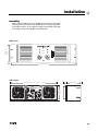
1
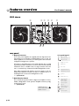
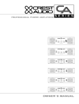
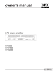
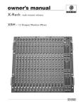
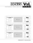
owner’s manual
8002 power amplifier
Professional Power Amplifier
8002
ACL
Signal
Status
-6
-10
-6
-10
-3
-15
-30
-80
Ch A
v. 1.0
*A4400076* 4/29/98
Crest Audio Inc.
100 Eisenhower Dr., Paramus NJ 07652 USA
TEL: 201.909.8700 FAX: 201.909.8744
http://www.crestaudio.com
-3
-15
-1
ØdB
-1
-30
-80
ØdB
Ch B
important precautions
1
Save the carton and packing materials!
Should you ever need to ship the unit,
use only the original factory packing.
¡
For replacement packaging,call Crest Audio’s
Customer Service Department directly.
2
3
4
5
6
Do not parallel- or series-connect
an amplifier output with any
other amplifier output.
Read all documentation before
operating your equipment. Retain all
documentation for future reference.
Follow all instructions printed on
unit chassis for proper operation.
Never hold a power switch in the
on-position, if it won’t stay there
by itself!
Do not use the unit if the electrical
power cord is frayed or broken.
The power supply cords should be
routed so that they are not likely to be
walked on or pinched by items placed
upon or against them.
Always operate the unit with the
AC ground wire connected to the
electrical system ground. Precautions
should be taken so that the means of
grounding of a piece of equipment is not
defeated.
7
Damage caused by connection to
improper AC voltage is not covered
by any warranty. Mains voltage must be
correct and the same as that printed on
the rear of the unit.
8
Do not ground any hot (red) terminal.
Crest Audio is not responsible for damage
to loudspeakers for any reason.
Ô
0
Power down and disconnect units
from mains voltage before making
connections.
Do not drive the inputs with a signal level greater than that
required to enable equipment to
reach full output.
Service Information
Do not remove the cover!
Removing the cover will expose you to
potentially dangerous voltages.There are
no user serviceable parts inside.
Equipment should be serviced by
qualified service personnel when:
A. The power supply cord or the plug has
been damaged.
Do not connect the inputs or outputs of amplifiers to any other
voltage source: such as a battery,
mains source, or power supply, regardless of whether the amplifier is turned
on or off.
B. The equipment has been exposed to rain.
C. The equipment does not appear to oper-
ate normally,or exhibits a marked change in
performance.
D. The equipment has been dropped, or the
£
Connecting amplifier outputs to
oscilloscopes or other test equipment while the amplifier is in bridged
mono mode may damage both the
amplifier and test equipment!
¢
Do not spill water or other liquids
into or on the unit, or operate the
unit while standing in liquid.
ˆ
Do not block fan intake or
exhaust ports.
Do not operate equipment on a
surface or in an environment
which may impede the normal
flow of air around the unit: such as
a bed, rug, weathersheet, carpet, or
completely enclosed rack.
§
If the unit is used in an extremely
dusty or smoky environment: the
unit should be periodically “blown free”
of foreign matter.
¶
Do not use the unit near stoves,
heat registers, radiators, or other
heat producing devices.
ƒ
The power cord of equipment
should be unplugged from the outlet when left unused for a long period of time.
Never connect a hot (red) output to
ground or to another hot (red) output!
9
Do not run the output of any amplifier channel back into another
channel’s input.
enclosure damaged.
To obtain service:
contact your nearest Crest Audio
Service Center, Distributor, Dealer,
or Crest Audio at 201.909.8700 USA
or visit www.crestaudio.com for additional information.
email
[email protected]
This symbol is used to alert
the operator to follow important
procedures and precautions
detailed in documentation.
This symbol is used to warn operators
that uninsulated “dangerous voltages”
are present within the equipment enclosure
that may pose a risk of electric shock.
table of contents
1
how to use this manual
introduction p.3
2
installation
3
features overview
4
5
p.2
p.5
unpacking
mounting
cooling and ventilation
powering
maintenance
p.11
front panel
rear panel
operation modes
p.17
stereo
parallel
bridged
contents
connections
p.21
input
output
6
safety
7
service and support
a
specifications
p.36
b
block diagram
p.37
c
wire gauge charts
p.27
tourclass protection
precautions
user responsibility
p.33
support
contact us
registration
appendixes
p.38
p. 1
1
how to use this manual
conventions
terms
official Crest Audio features and
each indicator or control on the amplifier will appear as: terms
actions
specific actions or selections the user can execute will appear as: actions
tasks
are broken down into steps 1
2
3
warnings
Procedures not to attempt.
Issues or hazards to keep
in mind when operating
the equipment.
a
indicators
What to look for on
the equipment display.
Alerts, indicators, or
prompts that may appear.
®
tips
Prefered methods.
Helpful hints.
Feature insights.
+
see
see—refers to other sections of the manual containing
supplementary information on the current topic or a related issue
note
note—supplimentary feature information
p. 2
Pro II owner’s manual
introduction
1
welcome
Congratulations on your purchase of a new Pro II Series professional
power amplifier, and thank you for your confidence in Crest Audio products.You are among the growing number of audio professionals who have
made Crest Audio one of the world’s leading suppliers of professional and
commercial/industrial audio systems.
For your safety, please read the Important Precautions section before
installing and operating the amplifier.The Crest Audio Pro II Series is based
on the same advanced circuit topologies that have made Crest’s original
Professional Series amplifiers the choice of touring professionals worldwide. Pro II Series amplifiers are designed for high operating efficiency and
accurate sonic performance across the full audio bandwidth, even under
stressful conditions.
The Pro II Series heralds a major advance in amplifier design from Crest
Audio, providing the extreme reliability and hallmark sonic accuracy for
which Crest products are famous, in a rugged package but at only half the
weight of previous models of similar power.These dramatic weight savings
are made possible by PowerLok, a radical new power-supply technology
that provides significant performance and flexibility advances over conventional designs.PowerLok is Crest Audio's unique implementation of Power
Factor Correction, which allows current to be drawn throughout the
entire cycle of the AC line-frequency, providing maximum output power,
while drawing significantly smaller peak currents from the AC line.
Compared with an amplifier using a conventional power-supply, PowerLok
requires less peak power to produce identical output power, and because
PowerLok's current peaks are smaller, a Pro II amplifier can be serviced by
a lower-rated breaker than a conventional amplifier of similar wattage. See
separate literature for full details on the benefits of PowerLok technology.
In order to maintain strict quality assurance standards, all Crest Audio
power amplifiers are built in our state-of-the-art USA manufacturing facility. Internal components are the finest available and key sub-assemblies are
pre-tested before final assembly. Each amplifier is “burned in” and thoroughly tested (using precision audio test equipment) before shipping. In
addition, all Pro II Series amplifiers incorporate Crest’s exclusive TourClass
protection features to safeguard both internal circuitry and connected
loudspeakers.
This proven combination of advanced design, quality construction, and
comprehensive circuit protection is your guarantee of fail-safe reliability.
You can depend on consistent, stable performance even when your Pro II
Series amplifier is subjected to punishing extremes in the most demanding
fixed or mobile sound reinforcement applications.
p. 3
p. 4
installation
/
what to do with the shipping carton
/
proper rack-mounting technique
/
keeping the amplifier cooled
/
grounding the amplifier
/
required AC line voltages
/
routine maintenance practices
2
unpacking
mounting
cooling and
ventilation
powering
maintenance
p. 5
2
installation
Pro II owner’s manual
unpacking
Please inspect the amplifier carefully immediately after unpacking. If you find
any damage, notify your supplier/dealer immediately. Only the shipper may
file a damage claim with the carrier for damage incurred during shipping. Be
sure to save the carton and all packing materials for the carrier’s inspection.
If the packing materials are in good condition, please save them.
If you ever need to ship the unit back to Crest Audio or an authorized service center, you should use only the original factory packing.
For replacement packaging, call Crest Audio’s
Customer Service
Department directly.
+
see—service and support
p. 6
installation
2
mounting
All Pro II Series amplifiers mount in standard 19-inch racks. Four front-panel
mounting holes are provided on each amplifier.Rear mounting ears give additional support, and use of rear supports is highly recommended in all mobile
and touring sound systems. Handles are fitted standard.
8002 shown
Professional Power Amplifier
8002
ACL
front
height
5.25" /
133mm
Signal
Status
-6
-10
-6
-10
-3
-15
-3
-15
-1
-30
-80
ØdB
-1
-30
-80
Ch A
ØdB
Ch B
front width 19"/ 483mm
8002 shown
depth 18"/457mm
rear width 17"/ 432mm (19” /483mm to rack ears)
35mm
rear
height
5.25" /
133mm
p. 7
2
installation
Pro II owner’s manual
cooling and ventilation
Pro II Series amplifiers use a twin-tunnel forced-air cooling system to maintain a low, even operating temperature.
Drawn in by dual 105 CFM (cubic feet-per-minute) DC fans on the rear panel,
air flows through the cooling fins of the channel heat-sinks,dissipating power
transistor heat—then exhausts through the front panel slots.
Heat sink temperature-sensing circuits control the “intelligent” variablespeed fans.Fan speed increases only as required by heat-sink temperatures—
keeping fan noise to a minimum.
Under extreme thermal load, the fans will force a very large volume of air
through the heat sinks. If either heat-sink surpasses the maximum allowed
temperature, the sensing circuit will open the output relay, disconnecting the
load from that channel.
If the power supply overheats, another sensing circuit opens both channel
output relays, until it has cooled to a safe temperature.
p. 8
a
To ensure optimum
cooling of the amplifier,
periodically clean its fan
filters. These are removable
without tools.
Make certain that there is
enough space around the
front of the amplifier
to allow the heated air to
escape. If the amplifier is
rack-mounted, do not use
doors or covers on the front
of the rack; the exhaust air
must not be impeded
In racks with closed backs:
for every four amplifiers,
allow at least one standardrack-space opening in the
front of the rack.
installation
2
powering
Unless otherwise specified when ordered, Pro II amplifiers shipped to customers are configured as follows:
North America 90–255 VAC @ 50–60Hz
Europe
180–255 VAC @ 50–60Hz
Asia
180–255 VAC @ 50–60Hz
Australasia
180–255 VAC @ 50–60Hz
a
Always turn off and disconnect the amplifier from
mains voltage before making audio connections.
As an extra precaution, have
the attenuators turned down
during power-up.
South America 90–255 VAC @ 50–60Hz
Japan
90–255 VAC @ 50–60Hz
maintenance
A Pro II Series amplifier requires no routine maintenance other than the
occasional cleaning or replacement of the fan intake filters on the rear of the
amplifier. (This operation does not require any tools.) Filters must be kept
clear and clean to ensure proper ventilation through the unit.
If the amplifier is used in an extremely dusty or smoky environment, the filter should be cleaned or changed frequently and the unit should be periodically “blown free” (using compressed air) of any foreign matter that may have
penetrated the filter.
Cover removal exposes
the risk of shock, so refer
all servicing to qualified
service technicians authorized by Crest Audio.
a
Users will not need to make any internal adjustments to the amplifier during its lifetime. There are no user-serviceable parts or adjustments that
require opening the power amplifier.
p. 9
p. 10
features overview
/
location of connectors and controls
/
legend of panel symbols
3
front panel
rear panel
p. 11
3
features overview
Pro II owner’s manual
8002 shown
1
2
3
6 7
5
4
8
Professional Power Amplifier
8002
ACL
Signal
Status
-6
-10
-6
-10
-3
-15
-1
-30
-80
Ch A
p. 12
-3
-15
ØdB
-1
-30
-80
ØdB
Ch B
features overview
3
front panel
1 Rack Mounting Ears
Two front-panel mounting holes are provided on each mounting ear.
2 Rack Handles
3 Fan Outlet Grills
Pro II Series amplifiers are cooled by two, rear-mounted fans. Cool air
flows over the heat sinks and exhausts through the front grills. Make
sure these outlets remain clear to allow unrestricted airflow.
4 Signal LED
A variable-intensity LED that illuminates to indicate that a signal (above
a minimum threshold) is present at the amplifier input,and that the signal is being amplified.
5 Input Attenuators
Two input attenuators adjust level for their respective amplifier channels. In Bridged Mono mode, the channel A attenuator controls signal
level.
6 Status LED
A bi-color LED.When green, it indicates that AC power is connected
and the amplifier is turned on.When red,the channel is in Protect mode
(speakers disconnected by output relay).
7 ACL LED
Illuminates at the clipping threshold. Continuous illumination also indicates that ACL ACTIVE CLIP LIMITING protection circuitry is engaged.
8 AC Power Switch/Circuit Breaker
Pro II Series amplifiers have a front-panel combination AC switch/circuit breaker. (No fuses are used.) If the switch shuts off during normal
use,push it back to the on-position once.If it will not stay on,the amplifier needs servicing.
Never try to hold the
circuit breaker/power
switch in the on-position,
if it won’t stay there itself!
a
note—all LEDs are one per channel
p. 13
3
features overview
Pro II owner’s manual
8002 shown
1
2 3 4 5
6
7 8
rear panel
1 Output Connectors
rear panel legend
input connection
2+
1
3-
+
Pro II Series power amplifiers are supplied with both high-current fiveway binding posts and Speakons installed. Binding posts: one pair per
channel. Speakons: one connector per channel, plus a third connector
configured for bridged-mono operation.
XLR
connector polarity
TRS
connector polarity
A
bridged mono mode
AB
Connection to the binding posts can be made with bare wire or spade
lug terminations. Make connections to both the channel A and channel B
terminals for Stereo or Parallel mode, or a single connection across the
red (hot) terminals only of channels A and B for Bridged Mono mode.
A
parallel mode
A B
A B
stereo mode
A B
chassis ground lifted-position
Using cables terminated with Speakon connectors, attach to both the
channel A and channel B connectors for Stereo or Parallel mode, or to
the Bridged mode connector/s for Bridged Mono mode.
dBu
see—operation modes
XLR Pin +
chassis ground grounded-position
GAIN
gain select
Ø 40x 20x
2
XLR pin 2/3 hot (+)
3
2 Mode Selection Switch
This recessed, three-position switch configures the amplifier for Stereo,
Parallel or Bridged Mono mode operation. Amplifiers are factory-configured for Stereo mode.
see—operation modes
output connection
speakon output
A
channel A stereo/parallel
B
channel B stereo/parallel
GAIN
Ø 40x 20x
dBu
A
bridged mono
B
XLR Pin +
Do not adjust the mode
selection switch while the
amplifier is turned-on.
a
five-way binding post
2
+
+
A
B
+
B
p. 14
3
channel A stereo/parallel
A
bridged mono
channel B stereo/parallel
features overview
3
rear panel
3 Female Balanced XLR Input Connectors
4 Male Balanced XLR Input Connectors
These connectors accept input signals on balanced male and female
XLR input plugs. Connectors for each channel are in parallel; any
unused XLR connectors may be used for daisy-chaining input connections to other amplifiers.
In Parallel and Bridge Mono mode a signal applied to channel A’s input
connectors will appear also at channel B’s.
Never connect a hot (red)
output to ground or to
another hot (red) output!
a
5 Input Sensitivity/Gain Switch
The Pro II Series amplifiers come standard set to x40 gain.
The Input Sensitivity/Gain switch allows the user to select either
.775 (0dB) sensitivity, x40, or x20 gain.
6 Fan Inlet Ports and Filters
Cooling air enters the amplifier through the fan inlet ports located on
the rear of the amplifier chassis.Be sure not to block these ports when
installing the amplifier or other associated equipment.Air must flow
unimpeded. Fan filters (removable without tools) are provided to minimize entry of dust and dirt.
7 Input XLR Polarity Switch
Pro II Series amplifiers are supplied standard with the XLR configured
as Pin 2 hot (+). Use the XLR polarity switch to change this setting to
Pin 3 hot (+) if desired.
8 Signal Ground-Lift Switch
The recessed signal ground-lift switch electrically connects signal
ground to the chassis/AC ground. This switch is factory-set to the
ground position (bottom). The top position lifts the amplifier’s signal
ground.In a properly designed system (for safety purposes and to minimize noise),amplifiers should be connected to ground through the AC
line cord.
Whenever possible, the signal source equipment should share the
same AC ground as the amplifier. In some cases this may not be possible, and a ground loop results. If this happens, the first step is to move
the ground-lift switch to the lifted position (top).In this position,the signal ground is lifted and completely isolated from the chassis/AC
ground. Do not change the switch to the lifted position if the amplifier and the signal source equipment are on the same AC ground.
Should the ground loop problem persist after the ground-lift switch
has been set to the lifted position, then the shield on balanced input
lines should be grounded at one end only (usually the signal source).
p. 15
p. 16
operation modes
/
choosing the appropriate mode
/
switching between operation modes
/
keeping the amplifier cooled
/
special considerations when using bridged mode
4
stereo
parallel
bridged
p. 17
4
operation modes
Pro II owner’s manual
mode selection
The three-position, recessed Mode Select switch (located on the rear panel)
configures the amplifier for Stereo, Parallel or Bridged mode. Amplifiers are
factory-configured for Stereo mode.
stereo
In Stereo mode, both channels operate independently, with their input attenuators controlling their respective levels.Signal at Channel A’s input produces
output at Channel A’s output,while signal at Channel B’s input produces output at Channel B’s output.Recommended minimum nominal load impedance
for stereo operation is 2 ohms per channel. Either the male or female XLR
inputs may be used.
parallel
When set to Parallel mode,a signal applied to Channel A’s input will be amplified and appear at outputs for both Channels A and B. Either the male or
female XLR input on Channel A may be used. Individual channel attenuators
control signal level.
bridged
Bridged mode straps both amplifier channels together to make a very powerful, single-channel monaural amplifier. One channel “pushes” and the other
“pulls” equally, doubling the power over that of either channel alone. Signal is
applied to the Channel A input only. Channel A’s attenuator is used to control signal level. Either male or female XLR input may be used.
The channel B input connectors (male or female XLR) may be used to daisychain the channel A signal when in parallel or bridged mono mode. Use
extreme caution when operating the amplifier in Bridged mode. Never
ground either side of the speaker cable when the amplifier is in Bridged
mode; both sides are “hot.”
If an output patch panel is used, all connections must be isolated from each
other and from the panel.The recommended minimum nominal load impedance in the Bridged mode is 4 ohms, which is the equivalent to driving both
channels separately at 2 ohms.
see—connections for examples of mode-specific wirings
p. 18
Driving bridged loads
of less than the recommended minimums will
activate the IGM circuitry,
resulting in a loss of power,
and may also lead to a
thermal protect condition.
a
Connecting amplifier
outputs to oscilloscopes
or other test equipment
while the amplifier is
in bridged mode may
damage both the amplifier
and test equipment!
a
operation modes
4
p. 19
p. 20
connections
/
/
proper wiring schemes for connectors: XLR
speakon
binding post
input
correct signal paths: stereo, parallel, and bridged
output
5
p. 21
5
connnections
Pro II owner’s manual
inputs
Use either male or female XLR connectors on the rear to supply audio signals to the inputs of your Crest Audio Pro II Series amplifier.
Some other Crest Audio
amplifiers are configured
with pin 3 hot.
a
Pro II Series amplifiers are configured standard with pin 2 hot on XLR inputs.
The input XLR polarity switch can configure pin 3 hot if required.
male XLR
1 - Ground ( )
3 - Negative (-)
+
The unused connector
can be used to jumper
the audio input to another
amplifier input.
2 - Positive (+)
female XLR
input sensitivity options
position 1
position 2
position 3
gain
sens
Ø
x40
x20
.775V
2.0V
4.0V
outputs
Speakers are connected using the high-current five-way binding posts
or speakon connectors, or both, depending on preference and model.
stereo/parallel
see—operation modes
p. 22
bridged mono
Very high current is
available at the outputs.
Please connect your
output cable to the + and terminals of each section
precisely as shown.
a
connections
5
stereo mode
five-way binding post connectors
Unused XLR connectors can be
utilized to daisy-chain a signal
source to additional amplifiers.
parallel mode
five-way binding post connectors
bridged mono mode
five-way binding post connectors
Unused XLR connectors can be
utilized to daisy-chain a signal
source to additional amplifiers.
Unused XLR connectors can be
utilized to daisy-chain a signal
source to additional amplifiers.
p. 23
5
connnections
Pro II owner’s manual
stereo mode
speakon output connectors
Unused XLR connectors can be
utilized to daisy-chain a signal
source to additional amplifiers.
parallel mode
speakon output connectors
Unused XLR connectors can be
utilized to daisy-chain a signal
source to additional amplifiers.
bridged mono mode
speakon output connectors
Unused XLR connectors can be
utilized to daisy-chain a signal
source to additional amplifiers.
p. 24
connections
5
p. 25
p. 26
safety
/
the owner’s role in amplifier safety
/
description of TourClass protection features
/
protecting your speakers
6
user
responsibility
speaker
protection
TourClass
p. 27
6
safety
user responsibility
Your Pro II Series amplifier is very powerful and can be potentially dangerous to loudspeakers and operators alike. It is your responsibility to
read important precautions (see the inside-front cover) and make
sure that the amplifier is installed, wired, and operated properly as
instructed in this manual.
Many loudspeakers can be easily damaged or destroyed by overpowering, especially with the high power available from a bridged amplifier.
Always be aware of the speaker’s continuous and peak power capabilities. Crest Audio is not responsible for damage to loudspeakers for
any reason.
see—speaker protection
p. 28
Pro II owner’s manual
safety
6
speaker protection
All loudspeakers have electrical, thermal, and physical limits which must be
observed to prevent damage or failure. Cone or compression drivers can
be damaged (sometimes to the point of failure) from excessive power, low
frequencies applied to high frequency drivers, severely clipped waveforms,
and DC voltage. All Pro II Series amplifiers automatically protect speakers
from DC voltages and subsonic signals.
see—TourClass protection
Mid- and high-frequency transducers—compression drivers in particular—
are highly susceptible to damage from overpowering, clipped waveforms,
or frequencies below their rated passband. When using an electronic
crossover, make absolutely certain that the low and mid bands are connected to the correct amplifiers and drivers—and not accidentally connected to those for a higher or lower frequency band.
The amplifier’s clipping point is its maximum peak output power. At maximum peak output power, Crest Audio Pro II Series amplifiers will deliver
more power than many speakers can safely handle. Be sure the peak
power capability of the amplifier is not excessive for your speaker system.
To ensure that the speakers never receive excessive power,and to prevent
amplifier clipping, use a properly adjusted external limiter (or a compressor with a ratio of 10:1 or higher) to control power output.Use one compressor/limiter for each frequency band in systems with active electronic
crossovers.
The ACL clip limiting circuit will automatically limit the duration of
squared-off, continuous waveforms applied to the speakers.The amplifier
will, however, allow normal musical transient bursts to pass. Of course,
when the amplifier does clip, it is operating at its maximum output power.
Note that some speaker systems are packaged with proprietary “processors” that have power limiting circuits and therefore should not require
additional limiting.Do not drive any low-frequency speaker enclosure with
frequencies lower than its own tuned frequency; the reduced acoustical
damping could cause a ported speaker to “bottom out” even at moderate
power. Consult the speaker system specifications to determine its frequency limits, and employ a roll-off filter if necessary.
recommended speaker cabling
The wire gauge charts will assist you in determining the optimum copper
wire gauge for your speaker cables. Remember that the speaker cable
resistance robs amplifier power in two ways: through power lost directly
to resistance (often referred to as I2R loss), and through increased total
load resistance, which decreases the amount of power available from the
amplifier. Appendix C gives cable length figures in feet/AWG wire gauges
and in metric values.
see—wire gauge
p. 29
6
safety
TourClass ® protection
Every model in the Pro II Series incorporates TourClass protection features. Derived from Crest Audio’s extensive experience with the world’s
largest sound rental companies, the TourClass group of circuits sets the
industry standard for assured protection of internal amplifier circuits and
all connected loads.
ACL ACTIVE CLIP LIMITING
At the amplifier’s full power limit, or clipping point, ACL will be activated.
This is indicated by illumination of the ACL LED.The channel gain is automatically reduced, protecting the loudspeakers from potential damage from
the high power, continuous square waves that would otherwise be produced. ACL may be activated by uncontrolled feedback,oscillations,improper equipment gain settings, or an equipment malfunction upstream from
the amplifier. Only steady or excessive clipping (not normal program transients) will trigger ACL. The circuit is virtually transparent in operation and
full signal bandwidth is maintained.
IGM INSTANTANEOUS GAIN MODULATION
IGM is an innovative circuit that allows the amplifier to operate safely into
loads as low as 2 ohms.When the amplifier sees a load that overstresses the
output stage, the IGM circuit adjusts the channel gain to a safe level. Like ACL,
the IGM circuit is inaudible in normal use.In addition,if extreme and sustained
low impedance is encountered, the amplifier’s output relay will open.
AutoRamp
Auto Ramp operates every time the amplifier is turned on or is reactivated
after a protect condition is corrected. This exclusive Crest Audio feature
gradually increases gain to the attenuator setting avoiding unnecessary stress
on the loudspeakers.
Thermal
Abnormally high heat sink temperatures will engage the Protect circuit for the
overheating channel only. (An output relay disconnects the loudspeakers until
nominal temperature range is restored.) During this time, the Status LED will
light red. If the power supply gets too hot, its thermal sensing circuit will disconnect both channel outputs. During this time, the Active LED will extinguish, the Status LED will remain red, and the cooling fan will continue running at high speed. Normal operation resumes once the power supply cools
to a safe level.
Short Circuit
If an output is shorted (i.e., defective speakers or crossed speaker wires) the
IGM and thermal circuits will automatically protect the amplifier.The IGM circuit senses the short circuit as an extremely stressful load condition and
attenuates the signal, protecting the channel’s output transistors from overcurrent stress. If the short circuit remains, the load will be disconnected by
the thermal protection circuitry (the output relay opens).
p. 30
Pro II owner’s manual
safety
6
DC Voltage
If an amplifier channel detects DC voltage at its output terminals, the output relay will immediately open to prevent loudspeaker damage.The Status
LEDs will turn red.
Subsonic Frequencies
Built-in high pass filtering provides subsonic frequency protection for each
channel. In addition, a relay will open if excessive subsonic energy appears
at the output.
p. 31
p. 32
service and support
/
when to get support
/
ways to contact Crest Audio
7
support
contact us
p. 33
7
service and support
Pro II owner’s manual
support
In the unlikely event that your amplifier develops a problem, it must be
returned to an authorized distributor, service center or shipped directly to
our factory.
To obtain service, contact your nearest Crest Audio Service Center,
Distributor, Dealer, or any of the worldwide Crest Audio offices. For those
with Internet access, please visit the Crest Audio website.
Because of the complexity
of the design and the risk
of electrical shock,
all repairs should be
attempted only by qualified
technical personnel.
a
If the unit needs to
be shipped back to the
factory, it must be sent
in its original carton.
If improperly packed, your
amplifier may be damaged.
a
contact us
customer service
phone 201.909.8700 USA
fax
201.909.8744 USA
email [email protected]
technical support
phone 201.909.8700 USA
fax
201.587.0550 USA
email [email protected]
website
www.crestaudio.com
mail
Crest Audio Inc.
100 Eisenhower Drive
Paramus, NJ 07652 USA
p. 34
For replacement packaging, call Crest Audio’s
Customer Service
Department directly.
+
service and support
7
p. 35
specifications
a
Pro II owner’s manual
8002
Stereo power 8Ω
1kHz, 0.1% THD+N
20Hz–20kHz, 0.1% THD+N
800W
750W
4Ω
1400W
1350W
2Ω
2000W
1900W
Bridged mono power 8Ω
2800W
2700W
4Ω
4000W
3800W
Maximum output voltage
Frequency response 1W @ 8Ω
Power bandwidth rated power @ 4Ω, 1% THD+N
THD+N
SMPTE IMD
Damping factor
Input CMRR
Switch-configurable input options
Input impedance
Hum and noise
Crosstalk
Class
Power supply
Circuit breaker rating 4Ω
Current draw 1/8 power, 4Ω
1/3 power, 4Ω
92V rms, 130V peak each channel
20Hz–20kHz, +0 / -0.3dB, -3dB@135kHz
20Hz–20kHz, +0 / -0.23dB
<0.05% rated power @ 4Ω, 1kHz
<0.01% rated power @ 8Ω, 60Hz and 7kHz
400:1 10–400Hz @ 8Ω
>60dB @ 1kHz
.775V constant sensitivity, x20 or x40 constant gain
>20kΩ balanced, >10kΩ unbalanced
-110dB, A-weighted below rated power
> -80dB @ 1kHz below rated power
H
two versions: 90–255 or 180–255 vac @ 50–60Hz factory configured
PowerLok power supply with active power factor correction
36A
@ 120V
<7.7A
@120V
<17.3A
@120V
at power-up
<50A
@120V
at idle
<1.5A
@120V
Peak current draw
51A
Thermal emissions 1/8 Power, 4Ω
2083 BTU/Hr
1/3 Power, 4Ω
3899 BTU/Hr
Cooling
Input connectors
Output connectors
Controls
back-to-front via two rear-mounted variable-speed DC fans
female and male xlr pin 2+ switch-configurable for pin 3+
speakon connectors and five-way output binding posts
front panel: two attenuators, power switch incorporating magnetic circuit breaker
rear panel: signal ground-lift, mode select, input sensitivity, pin 2/3+
LED indicators
TourClass® protection
Construction
Dimensions
Weight
Warranty
acl, signal, status bi-color: active / protect
acl, igm, autoramp, short circuit, dc voltage, turn-on/-off transient,
current in-rush, sub/ultrasonic input
aluminum chassis
double thickness in rack-ear areas
height x width x depth
5.25” x 19” x 18”
133 x 483 x 457mm
gross: 47lbs 21.7kg
net: 42lbs 19.1kg
five years USA, Canada, United Kingdom, and many other countries
see—connections for input sensitivity options
p. 36
block diagram
b
p. 37
c
wire gauge
stranded cable length
2
5
meters
meters
10
meters
30
p. 38
Pro II owner’s manual
wire gauge
power loss
8Ω load
4Ω load
2Ω load
0.3mm2
2.9%
5.6%
10.8%
0.5
1.74
3.4
6.7
0.75
1.16
2.3
4.5
1.5
0.58
1.16
2.3
2.5
0.35
0.70
1.39
4.0
0.22
0.44
0.87
0.5mm2
4.3%
8.2%
15.5%
0.75
2.9
5.6
10.8
1.5
1.45
2.9
5.6
2.5
0.87
1.74
3.4
4
0.55
1.09
2.2
6
0.37
0.73
1.45
0.5mm2
8.24%
5.5%
28%
0.75
5.6
10.8
19.9
1.5
2.9
5.6
10.8
2.5
1.74
2.9
6.7
4
1.09
1.74
4.3
6
0.73
1.09
2.9
15.5%
0.73%
45%
1.5
8.2
15.5
28
2.5
5.1
9.8
18.2
4
3.2
6.3
12.0
6
2.2
4.3
8.2
10
1.31
2.6
5.1
meters 0.75mm2
wire gauge
stranded cable length
5
feet
10
feet
40
80
feet
feet
wire gauge
c
power loss
8 Ω load
4 Ω load
2 Ω load
18 AWG
0.81%
1.61%
3.2%
16
0.51
1.02
2.0
14
0.32
0.64
1.28
12
0.20
0.40
0.80
10
0.128
0.25
0.51
18 AWG
1.61%
3.2%
6.2%
16
1.02
2.0
4.0
14
0.64
1.28
2.5
12
0.40
0.80
1.60
10
0.25
0.51
1.01
18 AWG
6.2%
11.9%
22%
16
4.0
7.7
14.6
14
2.5
5.0
9.6
12
1.60
3.2
6.2
10
1.01
2.0
4.0
8
0.60
1.20
2.4
18 AWG
11.9%
22%
37%
16
7.7
14.6
26
14
5.0
9.6
17.8
12
3.2
6.2
11.8
10
2.0
4.0
7.7
8
1.20
2.4
4.7
p. 39
owner’s manual
8002 power amplifier
Professional Power Amplifier
8002
ACL
Signal
Status
-6
-10
-6
-10
-3
-15
-30
-80
Ch A
v. 1.0
*A4400076* 4/29/98
Crest Audio Inc.
100 Eisenhower Dr., Paramus NJ 07652 USA
TEL: 201.909.8700 FAX: 201.909.8744
http://www.crestaudio.com
-3
-15
-1
ØdB
-1
-30
-80
ØdB
Ch B