1
SPLIT-TYPE AIR CONDITIONER
INDOOR
OUTDOOR
INDOOR
OUTDOOR
MODEL NAME AR18HSFNCWKNEU AR18HSFNCWKXEU BASIC MODEL AR18HSFSAWKNEU AR18HSFSAWKXEU
AR24HSFNCWKNEU AR24HSFNCWKXEU
AR18HSFSBURNEU AR18HSFSBURXEU
AR24HSFSBURNEU AR24HSFSBURXEU
AIR CONDITIONER
AR24HSFSAWKNEU AR24HSFSAWKXEU
AR18HSFSAWKNEU AR18HSFSAWKXEU
AR24HSFSAWKNEU AR24HSFSAWKXEU
CONTENTS
1. Precautions
3. Alignment and Adjustments
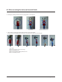
4. Disassembly and Reassembly
5. Disassembly WIFI
6. Electrical Parts List
7. Wiring Diagram
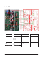
8. PCB Diagram
9. Operating Instructions
10. Troubleshooting
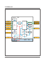
11. Block Diagram
12. Reference Sheet
Refer to the service manual in the GSPN (see the rear cover) for the More information
Contents
1. Precautions ············································································································· 1-1
1-1 Installing the air conditioner··························································································································
1-2 Power supply and circuit breaker·················································································································
1-3 During operation ················································································································································
1-4 Disposing of the unit·········································································································································
1-5 Others ······································································································································································
1-1
1-1
1-1
1-2
1-2
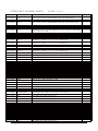
2. Product Specifications······························································································· 2-1
2-1 The Feature of Product ·····································································································································
2-2 Product Specifications ······································································································································
2-3 The Comparative Specifications of Product·····························································································
2-4 Accessory and Option Specifications ·········································································································
2-1
2-2
2-6
2-8
3. Alignment and Adjustments ········································································ 3-1
3-1 Test Mode·······························································································································································
3-2 Outdoor LED Display Error and Check Method ·····················································································
3-3 Setting Option Setup Method·······················································································································
3-4 Setting Option Setup Method·······················································································································
3-1
3-2
3-5
3-9
4. Disassembly and Reassembly ······································································ 4-1
4-1. Indoor Unit···························································································································································· 4-2
4-2. Outdoor Unit························································································································································ 4-12
5. Disassembly WIFI··························································································· 5-1
5-1 WIFI Case·································································································································································
5-2 ASSY CONTROL IN ··············································································································································
5-3 Assy Control Out ················································································································································
5-1
5-2
5-4
6. Electrical Parts List ························································································ 6-1
6-1 INDOOR MAIN PCB (DB92-02873A)·············································································································
6-4 OUTDOOR MAIN PBA(DB92-02866A) - 12K/18K ·····················································································
6-7 OUTDOOR MAIN PBA(DB90-02877A) - 24K······························································································
6-8 ASSY WIFI PCB ······················································································································································
6-1
6-5
6-11
6-20
7. Wiring Diagram······························································································ 7-1
7-1 Indoor Unit·····························································································································································
7-2 Outdoor Unit ························································································································································
7-3 ASSY WIFI KIT ························································································································································
Samsung Electronics
7-1
7-2
7-3
1
Contents
8. PCB Diagram ·································································································· 8-1
8-1 Indoor Unit·····························································································································································
8-2 Outdoor PCB ························································································································································
8-3 Wire connecting the indoor unit terminal blocks ·················································································
8-1
8-2
8-8
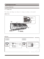
9. Operating Instructions·················································································· 9-1
9-1 Name of Each Part ··············································································································································
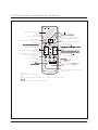
9-2 Wireless Remote Control-Buttons and Display·······················································································
9-1
9-2
10. Troubleshooting ··························································································10-1
10-1 Items to be checked first······························································································································· 10-1
10-2 Communication Error ····································································································································· 10-2
10-3 PCB Inspection Method································································································································· 10-37
10-4 ASSY WIFI KIT Inspection Method············································································································· 10-39
11. Block Diagram ·····························································································11-1
11-1 Indoor unit ·························································································································································· 11-1
11-2 Outdoor unit······················································································································································· 11-2
12. Reference Sheet···························································································12-1
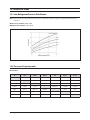
12-1 Low Refrigerant Pressure Distribution·····································································································
12-2 Pressure & Capacity mark······························································································································
12-3 Q & A for Non-trouble·····································································································································
12-4 Cleaning /Filter Change·································································································································
12-5 Installation···························································································································································
12-6 Installation Diagram of Indoor Unit and Outdoor Unit····································································
2
12-1
12-1
12-2
12-5
12-6
12-7
Samsung Electronics
1. Precautions
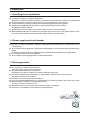
1-1 Installing the air conditioner
O Uses should not install the air conditioner by themselves.
Ask the dealer or authorized company to install the air conditioner except window-type air conditioner in U.S.A and Canada.
O If you don't install the air conditioner properly, it may cause a fire, a water leakage or an electric shock.
O You must install the air conditioner according to the national wiring regulations and safety regulations.
O Install the indoor unit higher than 2.5m from the floor to avoid the injury caused by the operation of the fan.
(except the window-type air conditioner)
O The manufacturer is not responsible for any accidents or injury caused by an incorrect installation.
O When installing the built-in type air conditioner, keep all electric cables such as the power cable and the connection cord in
pipes, ducts, or cable channels to protect them from the danger of impact or any other incidents.
1-2 Power supply and circuit breaker
O If the power cord of the air conditioner is damaged, it must be replaced by the manufacturer or a qualified person in order
to avoid a hazard.
O The air conditioner must be plugged into an independent circuit if applicable or connect the power cable to the auxiliary circuit
breaker.
An all pole disconnection form the power supply must be incorporated in the fixed wiring with a contact opening of>3mm.
O Do not extend an electric cord to the air conditioner.
O The air conditioner must be plugged in after you complete the installation.
1-3 During operation
O Do not repair the air conditioner at your discretion.
It is recommended to contact a service center directly.
O Never spill any kind of liquid on the air conditioner.
If this happens, turn off the air conditioner and contact an authorized service center.
O Do not insert anything between the airflow blades to prevent damage of the inner fan and consequent injury.
Keep children away from the air conditioner.
O Do not place any obstacles in front of the air conditioner.
O Do not spray any kind of liquid into the indoor unit. If this happens, turn off the air conditioner and contact a service center.
O Make sure that the air conditioner is well ventilated at all times.
Do not place a cloth or other materials over it.
O Remove the batteries if you don't use the remote control for a long time. (If applicable)
O Use the remote control within 7 meters from the indoor unit. (If applicable)
Samsung Electronics
1-1
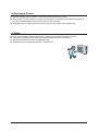
1-4 Disposing of the unit
O Before the throwing out the air conditioner, remove the batteries from the remote control.
O When you dispose of the air conditioner, consult your dealer. If pipes are removed incorrectly, refrigerant may blow out
and cause air pollution. When it contacts with your skin, it can cause skin injury.
O The package of the air conditioner should be recycled or disposed of properly for environmental reasons.
1-5 Others
O
O
O
O
1-2
Never store or load the air conditioner upside down or sideways to prevent the damage to the compressor.
Young children or infirm persons should be always supervised when they use the air conditioner.
Max current is measured according to IEC standard for safety.
Current is measured according to ISO standard for energy efficiency.
Samsung Electronics
2. Product Specifications
2-1 The Feature of Product
䒲 #2 step cooling
- Get cool quickly and keep cool comfortably without shivering
䒲 #Single user mode
- No worrying about the electricity bill, even using it when you're alone.
䒲 #Crystal gloss design
- Uniquely stylish and innovative design to enhance your life and home
䒲 #Smart Wi-Fi
- Control air conditioner anytime and anywhere
䒲 #Smart Installation
- Get the confidence that it's perfectly installed
䒲 #Smart Installation
- Get the confidence that it's perfectly installed
䒲 #Smart Check
- Don’t worry about the trouble-shooting in your home
䒲 #Triple Protector Plus
- Use longer without damage in unsuitable conditions
䒲 #Easy Installation
- Secure the easy Installation of Indoor unit and pipe connection
䒲 #Easy Filter
- Quick and easy to clean filter saves time and effort
Samsung Electronics
2-1
2-2
Operation condition range
NONE
-10ć~46ć
-15ć~24ć
NONE
-15ć~24ć
Heating
1150
-
R410
-10ć~46ć
1500
-
PROPELLER
L = 880mm / 7-9-11-13-14-17 (6turn)
2ROW x 10STEP x L840+
2ROW x 6STEP x L840
1ROW x 8STEP x L840+
1ROW x 4STEP x L840
CROSS-FLOW
Outoor Unit
NONE
NONE
-15ć~24ć
-15ć~24ć
-10ć~46ć
-
R410
1500
-10ć~46ć
BLDC
PROPELLER
52.4
1023*904*413
-
60
Wall-mounted
2-3
L = 880mm / 7-9-11-13-14-17 (6turn)
1500
2ROW x 10STEP x L840+
2ROW x 6STEP x L840
1ROW x 8STEP x L840+
1ROW x 4STEP x L840
BLDC
-
-
-
R410
BLDC
BLDC
Samsung Electronics
L = 880mm / 7-9-11-13-14-17 (6turn)
2ROW x 10STEP x L840+
2ROW x 6STEP x L840
1ROW x 8STEP x L840+
1ROW x 4STEP x L840
Cooling
g
Refrigerant to Change(R410A)
Proterction Device(OLP)
cc
BLDC
BLDC
Samsung Electronics
L = 880mm / 7-9-11-13-14-17 (6turn)
2ROW x 10STEP x L840+
2ROW x 6STEP x L840
1ROW x 8STEP x L840+
1ROW x 4STEP x L840
R410
BLDC
BLDC
motor
Type
CROSS-FLOW
Refrigerant Control Unit
CROSS-FLOW
-
PROPELLER
-
-
-
-
HERMETIC
HERMETIC
HERMETIC
Type
Rated Output(W)
HERMETIC
550±20
15.88 (5/8 inch)
6.35 (1/4 inch)
UG4T200FUAE4
CROSS-FLOW
14.06
UG4T200FUAE4
15.88 (5/8 inch)
6.35 (1/4 inch)
52.4
75/90/95
UG4T200FUAE4
PROPELLER
14.06
1123*354*384
UG4T200FUAE4
L*D
Type
Oil Type
Motor
Type
12.7 (1/2 inch)
15.88 (5/8 inch)
52.4
1023*904*413
75/90/95
550±20
6.35 (1/4 inch)
6.35 (1/4 inch)
14.1
75/90/95
75/90/95
75/90/95
1123*354*384
75/90/95
75/90/95
75/90/95
2.6/9.0/12.5
2.3/10.8/16.5
2.6/8.9/12.5
2.3/10.8/16.5
1.8/6.0/9.7
0.49/2.06/2.8
0.43/2.21/3.65
0.49/2.0/2.8
0.43/2.21/3.65
1.5/6.8/10.5
52.4
3.62
3.3
15/74/100
15/66/88
1.9/8.0/10.0
2.2/6.8/8.0
AR24HSFSRWK/ER
550±20
mm
Gas
14.06
-
51
Wall-mounted
Indoor Unit
1phase, 220-240V~, 50Hz
67
60
Wall-mounted
Outoor Unit
1phase, 220-240V~, 50Hz
3.62
3.4
15/74/100
15/66/88
1.9/8.0/10.0
2.2/6.8/8.0
AR24HSSDBWK/EU
2.6/9.0/13.0
1023*904*413
62
51
Wall-mounted
Indoor Unit
2.3/11.0/16.5
1123*354*384
0.3/1.46/2.1
1023*904*413
0.38/1.28/2.2
0.49/2.06/3.0
0.43/2.35/3.65
4.11
3.4
65
57
Wall-mounted
Outoor Unit
1phase, 220-240V~, 50Hz
3.9
58
46
3.3
67
15/44/73
15/54/75
15/66/88
15/74/100
62
1.2/6.0/8.2
AR18HSSDBWK/EU
1.6/5.0/6.0
Wall-mounted
Indoor Unit
2.2/6.8/8.0
Wall-mounted
Outoor Unit
1.9/8.0/10.0
AR24HSFNBWK/EU
1phase, 220-240V~, 50Hz
1123*354*384
60
51
Wall-mounted
Indoor Unit
550±20
mm
kg
mm
Liquid
Heat Exchanger
Blower
Compressor
Drain Hose
Refrigerant Pipe
Weight(Net)
W*D*H
Cooling
%
Heating (Low/Std/Max)
Power Factor
Gross Dimension
Cooling
A
Heating (Low/Std/Max)
Operating Current
ph-V-Hz
Cooling
KW
Heating (Low/Std/Max)
Heating
Cooling
W/W
(Std)
dB
(H/L)
⭿☚
⭿┮䘖
Hz
(Low/Std/Max)
Cooling
Heating
KW
(Low/Std/Max)
Cooling
Heating
Power Consumtion
Power
Energy Efficiency
Ratio
Noise
Running Frequency
Capacity
Type
MODEL
Freezer Oil Capacity
Size
Pow
Performance
ITEM
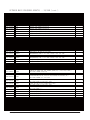
2-2 Product Specifications
Cooling
KW
Hz
L = 880mm / 7-9-11-13-14-17 (6turn)
2ROW x 10STEP x L840+
2ROW x 6STEP x L840
1ROW x 8STEP x L840+
1ROW x 4STEP x L840
2-2
-10 ~46
-15 ~24
Heating
NONE
1500
Cooling
g
-
R410
BLDC
BLDC
Type
motor
Refrigerant to Change(R410A)
Proterction Device(OLP)
PROPELLER
-15 ~24
-10 ~46
NONE
1150
-
R410
L = 880mm
BLDC
PROPELLER
Samsung Electronics
2ROW x 10STEP x L840+
2ROW x 5(6)STEP x L840
BLDC
CROSS-FLOW
-
1123*354*384
-15 ~24
-15 ~24
-15 ~24
-10 ~46
NONE
-10 ~46
NONE
-10 ~46
NONE
1500
1150
2-3
L = 880mm / 7-9-11-13-14-17 (6turn)
R410
BLDC
2ROW x 10STEP x L840+
2ROW x 6STEP x L840
1ROW x 8STEP x L840+
1ROW x 4STEP x L840
PROPELLER
52.4
1023*904*413
-
60
BLDC
880
R410
L = 880mm
BLDC
CROSS-FLOW
-
HERMETIC
UG4T200FUAE4
550±20
15.88 (5/8 inch)
6.35 (1/4 inch)
PROPELLER
14.06
-
HERMETIC
43.5
75/90/95
-
2ROW x 10STEP x L840+
2ROW x 5(6)STEP x L840
BLDC
550±20
12.7 (1/2 inch)
6.35 (1/4 inch)
UG4T150LNBEQ (44TBR150)
CROSS-FLOW
13.2
75/90/95
75/90/95
2.3/10.7/16.5
75/90/95
2.6/10.5/12.5
1.7/6.8/8.5
1.6/7.8/10.8
1023*760*413
0.49/2.12/2.8
0.43/2.16/3.65
0.3/1.45/1.9
0.26/1.66/2.4
1123*354*384
1phase, 220-240V~, 50Hz
3.62
Outoor Unit
W all-mounted
1phase, 220-240V~, 50Hz
3.61
-
51
15/74/100
15/66/88
1.9/7.8/10
2.2/6.8/8
AR24FSFNAWKNFA
3.3
65
58
W all-mounted
Indoor Unit
3.45
15/73/100
15/62/72
1.2/6.0/8.2
W all-mounted
Outoor Unit
-
R410
L = 880mm
BLDC
PROPELLER
Samsung Electronics
2ROW x 10STEP x L840+
2ROW x 5(6)STEP x L840
BLDC
CROSS-FLOW
-
-
-
-
-
HERMETIC
HERMETIC
HERMETIC
UG4T150LNBEQ (44TBR150)
43.5
1023*760*413
UG4T150LNBEQ (44TBR150)
Type
UG4T200FUAE4
550±20
12.7 (1/2 inch)
550±20
12.7 (1/2 inch)
550±20
15.88 (5/8 inch)
13.2
6.35 (1/4 inch)
43.5
6.35 (1/4 inch)
13.2
Rated Output(W)
cc
Operation condition range
1123*354*384
6.35 (1/4 inch)
52.4
CROSS-FLOW
Refrigerant Control Unit
1023*760*413
75/90/95
75/90/95
75/90/95
1123*354*384
75/90/95
75/90/95
75/90/95
1023*904*413
1.7/6.8/8.5
1.6/7.8/10.8
1.7/6.8/8.5
1.6/7.8/10.8
2.6/9.0/12.5
2.3/10.8/16.5
0.3/1.45/1.9
0.26/1.66/2.4
0.3/1.45/1.9
0.26/1.66/2.4
0.49/2.06/2.8
1phase, 220-240V~, 50Hz
0.43/2.21/3.65
3.61
1phase, 220-240V~, 50Hz
1123*354*384
57
3.61
46
W all-mounted
1.6/5.0/6.0
AR18HSFSBUR/EU
Indoor Unit
57
W all-mounted
Outoor Unit
46
3.45
-
57
3.45
3.62
-
1phase, 220-240V~, 50Hz
-
3.3
60
46
15/62/72
15/73/100
15/62/72
15/73/100
15/66/88
1.6/5.0/6.0
15/74/100
W all-mounted
1.2/6.0/8.2
W all-mounted
AR24HSFSBUR/EU
Indoor Unit
1.6/5.0/6.0
W all-mounted
Outoor Unit
1.2/6.0/8.2
-
14.06
AR18HSFNCWKNEU
Indoor Unit
2.2/6.8/8.0
W all-mounted
Outoor Unit
1.9/8.0/10.0
AR24HSFNCWKNEU
51
W all-mounted
Indoor Unit
Type
Oil Type
Motor
Type
L*D
mm
Gas
Heat Exchanger
Blower
Compressor
Drain Hose
Refrigerant Pipe
mm
kg
Weight(Net)
Liquid
mm
%
Heating (Low/Std/Max)
Cooling
Cooling
A
Heating (Low/Std/Max)
Gross Dimension W *D*H
Power Factor
Operating Current
Cooling
KW
Heating (Low/Std/Max)
ph-V-Hz
Power
Power Consumtion
W/W
(Std)
dB
(H/L)
Heating (Low/Std/Max)
Cooling
Heating (Low/Std/Max)
Energy Efficiency Cooling
Ratio
Heating
Noise
Running Frequency
Capacity
Type
MODEL
Freezer Oil Capacity
Size
Pow
Performance
ITEM
2-2 Product Specifications
Design
2-6
Air Purifying System
Noise
Outer Dimension
Net Weight
ITEM
Indoor Unit
Outdoor Unit
Indoor Unit
Outdoor Unit
Indoor Unit
Outdoor Unit
Filter
Outdoor Unit
Indoor Unit
MODEL
14.06
52.4
1123*354*384
1023*904*413
51/60
62/67
FULL HDFILTER
AR24HSFNBWK/EU
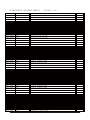
2-3 The Comparative Specifications of Product
Samsung Electronics
14.06
52.4
1123*354*384
1023*904*413
46/58
57/65
FULL HDFILTER
AR18HSSDBWK/EU
Samsung Electronics
Develop Model
14.06
52.4
1123*354*384
1023*904*413
51/62
60/67
FULL HDFILTER
AR24HSSDBWK/EU
14.06
52.4
1123*354*384
1023*904*413
51
60
FULL HDFILTER
AR24HSFSRWK/ER
2-7
Design
Outdoor Unit
Indoor Unit
MODEL
2-6
Net Weight
Indoo r Unit
Outdoor Unit
Indoor Unit
Outer Dimension
Outdoor Unit
I nd o or Un i t
Noise
Outdoor Unit
Filter
Air Purifying System
ITEM
14.06
52.4
1 12 3*3 5 4* 38 4
1023*904*413
51
60
FULL HDFILT ER
AR24HSFNCWKNEU
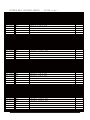
2-3 The Comparative Specifications of Product
Samsung Electronics
13.2
43.5
1 12 3 *35 4* 38 4
1023*760*413
46
57
FULL HDFILT ER
AR18HSFNCWKNEU
Samsung Electronics
13.2
43.5
112 3* 354 *384
10 2 3* 76 0* 41 3
46
57
FULL HDFILT E R
Develop Model
AR18HSFSBURNEU
14.06
52.36
1 123 *354 *384
10 23 * 04 *4 13
5
60
FULL HDFILTER
AR24HSFSBURNEU
14.06
52.36
1 123 *354 *384
10 23 *9 04 *4 13
51
60
FULL HDFILTER
AR24FSFNAWKNFA
2-7
2-4 Accessory and Option Specifications
I t em
Descr iptions
Co d e -N o .
Q 'T Y
Installation Plate
18(24) (05 frame)
DB90-07731A
1
Remote controller
18(24) (05 frame)
DB93-14195A
1
Batteries for Remote controller
4301-000121
2
Manual Users / Manual install
18(24) (05 frame)
DB68-04211A
DB68-04212A
1
Wi-Fi Manual
18(24) (05 frame)
DB68-04215A
1
M4x10 Tapped Screws
DB97-23032A
2
M4 x 16 Tapped Screws
DB97-11984A
2
Drain Plug
DB67-20011A
1
R ema r k
Indoor unit case
Outdoor unit case
Rubber Leg
2-8
DB73-20134A
4
Samsung Electronics
3. Alignment and Adjustments
3-1 Test Mode
Q How to Approach Test Mode
You can approach the test mode by pressing the on/off switch of
indoor unit for 5 seconds.
Q Test mode operation option
After installing the air conditioner, check whether each subordinate is normally operated or not by operating the test mode.
When an Error occurs, display the Error Mode.
● Operation Mode : Cool mode. operate the cool mode by operating the compressor by force without the compressor ON/OFF
according to the set temperature/indoor temperature. (Do not follow the antifreeze control)
● Up-down louver : Up-down swing mode
● Indoor Fan : Turbo
●
●
Note
Because the teat mode operate the cool mode by force not related to the set temperature / indoor
temperature, check whether each subordinate is operated normally or not after completing installation
and must turn off the power of the air conditioner.
Samsung Electronics
3-1
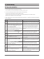
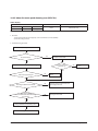
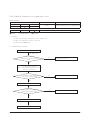
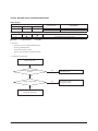
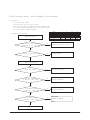
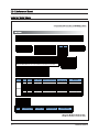
3-2 Display Error and Check Method
3-2-1 Indoor Display Error and Check Method
ER R O R M O D E
E101 / E102
3-2
D ES C R IP T IO N
Communication Error (Indoor Outdoor)
E121
ROOM TH sensor error
E122
INDOOR MID, INDOOR IN PIPE-TH sensor error
E154
Fan Error (Indoor)
E162
EEPROM Error (Indoor)
E163
Option Error
E203
Time out Comm. (Inv Micom
E221
OUT-TH(Outdoor Temperature) Sensor Error
E231
CON-TH(Cond Temperature) Sensor Error
E251
DIS-TH(Discharge Temperature) Sensor Error
E416
DIS-TH(Discharge Temperature) Over Error
E422
EEV or Valve Close error-Self diagnosis
E440
Prohibit Operation Condition Error (Heating)
E441
Prohibit Operation Condition Error (Cooling)
Main Micom)
E458
Fan Error(Outdoor)
E461
Comp Starting Error
E462
AC Input I_Limit Trip Error
E464
IPM Over Current(O.C) Error
E465
Comp V_limit/I_limit Error
E466
DC-Link Voltage Under/Over Error
E467
Comp Wire Missing Error
E468
Current Sensor Error
E469
DC-Link Voltage Sensor Error
E470
EEPROM Data Error (no data)
E471
EEPROM Data Error (Main Micom
E474
Heatsink Sensor Error
E483
Over Voltage Protection Error
E484
PFC Over Load Error
E485
Input Current Sensor Error
E488
AC Input Voltage Sensor Error
E500
Heatsink Over Temperature Error
E554
Gas Leak Error
Inv Micom)
Samsung Electronics
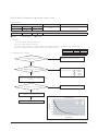
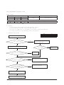
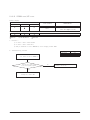
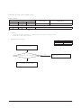
Outdoor LED Display Error and Check Method (12K/18K/24K)
LED PATTERN
YEL
GRN
DESCRIPTION
RED
Power off/VDD NG
Power ON reset(1sec)
Normal Operation
Abnormal Communication (Indoor Outdoor)
IPM Over Current(O.C) Error
Comp Starting Error
EEPROM Data Error (no data)
DC-Link Voltage Under/Over Error
PFC Over Load Error
Over Voltage Protection Error
OUT-TH(Outdoor Temperature) Sensor Error
DIS-TH(Discharge Temperature) Over Error
DIS-TH(Discharge Temperature) Sensor Error
Current Sensor Error
Heatsink Sensor Error
Input Current Sensor Error
Comp V_limit/I_limit Error
Heatsink Over Temperature Error
CON-TH(Cond Temperature) Sensor Error
Time out Comm. (Inv Micom Main Micom)
Fan Error(Outdoor)
EEPROM Data Error (Main Micom
Inv Micom)
Comp Wire Missing Error
Prohibit Operation Condition Error (Heating)
Prohibit Operation Condition Error (Cooling)
DC-Link Voltage Sensor Error
AC Input Voltage Sensor Error
AC Input I_Limit Trip Error
Gas Leak Error
EEV or Valve Close error-Self diagnosis
Test Operation at Cooling Mode
Test Operation at Heating Mode
LED ON,
Samsung Electronics
LED OFF,
LED BLINKING
3-3
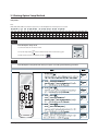
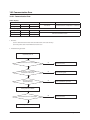
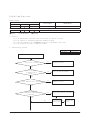
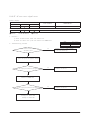
3-3 Setting Option Setup Method
ex) Option No. :
Note :
SEG1, SEG7, SEG13, SEG19 need not to be pressed in, so in fact the Option No. we should press in is as below.
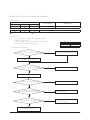
SEG1 SEG2 SEG3 SEG4 SEG5 SEG6 SEG7 SEG8 SEG9 SEG10 SEG11 SEG12 SEG13 SEG14 SEG15 SEG16 SEG17 SEG18 SEG19 SEG20 SEG21 SEG22 SEG23 SEG24
SEG25 SEG26 SEG27 SEG28 SEG29 SEG30 SEG31 SEG32 SEG33 SEG34 SEG35 SEG36 SEG37 SEG38 SEG39 SEG40 SEG41 SEG42 SEG43 SEG44 SEG45 SEG46 SEG47 SEG48
Step 1
Enter the Option Setup mode.
1. Tack out the batteries of remote control.
2. Press the temperature
button simultaneously and insert the battery again.
3. Make sure the remote control display shown as
.
Step 2
Enter the Options Setup mode and select your options asscording to the following procedure.
Samsung Electronics
3-5
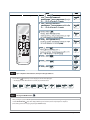
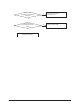
Step 3
Upon completion of the selection, check you made right selections.
Press the Mode
Selection key to set the display part and check the display part.
→ The display part shows like below when each time you press Mode button.
Step 4
Pressing the ON/OFF button (
).
When pressing the operation ON/OFF key with the direction of remote control for unit, the sound ’ Ding’’ or ’ Diriring’’ is heard
and the OPERATION ICON(
) lamp of the display is flickering at the same time, then the input of option is completed.
(If the deriving sound isn’t heard, try again pressing the ON/OFF button.)
3-6
Samsung Electronics
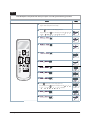
Step 5
Enter the Options Setup mode and select your options asscording to the following procedure.
Step 1 (Enter the Option Setup mode) is executed.
(Seg25 ~ 48 for setting remote control Setup)
Push the
Mode button to set the display panerl to 2.
Every time you push the
...
Push the
Samsung Electronics
...
repeatedly.
Mode button to set the display panerl to 1.
Every time you push the
button, the display panel reads
button, the display panel reads
repeatedly.
3-7
Step 6 Upon completion of the selection, check you made right selections.
Press the Mode
Selection key to set the display part and check the display part.
The display part shows like below when each time you press Mode button.
Step 7 Pressing the ON/OFF button ( ) .
When pressing the operation ON/OFF key with the direction of remote control for unit, the sound ’ Ding’’ or ’ Diriring’’ is hea
and the OPERATION ICON( ) lamp of the display is flickering at the same time, then the input of option is completed.
(If the deriving sound isn’t heard, try again pressing the ON/OFF button.)
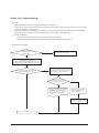
Step 8 Unit operation test-run.
First : Remove the battery from the remote control.
Second : Re-insert the battery into the remote control.
Third : Press ON/OFF key with the direction of remote control for set.
Error mode
1. If all lamps ofi ndoor unit are flickering, Plug out, plug in power plug again and press ON/OFF key to retry.
2. If the unit is not working properly or all lamps are continuously flickering after setting the option code, see if the c
orrect option code is
set up for its model.
Option Items
Model
AR18HSFNCWK/EU
AR24HSFNCWK/EU
AR18HSFSBUR/EU
AR24HSFSBUR/EU
3-8
1-6
010005
010005
010005
010005
7-12
13-18
19-24
25-30
31-36 37-42 43-48
15625C 274450 372604 03454F
10424A 200000 300000
17620A 27323C 372604
034A40 103E49 200000 300000
17620A 27323C 372604 034A40 103E49 200000 300000
15625C 274450 372604
03454F 10424A 200000 300000
Samsung Electronics
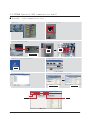
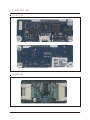
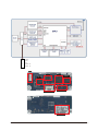
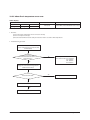
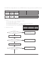
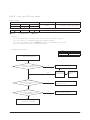
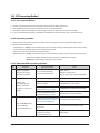
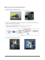
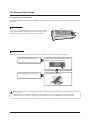
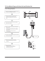
3-4 EEPROM Download (485 communication model)
Ƶ Method#1 : Using Communication line
1) Power off
2) Take off the side cover
3) Connect PC-Download Jig-PBA
F1,F2
(2pin)
F1,F2
(2pin)
RS 232 to 485
Converter
4) Execute the Inverter Download program
5) Select COM Port and connect
4) CLICK
6) Open the file (*.src)
7) Click the Start button and reset the power
Reset
power
Waiting down load
Download
6) CLICK
7) CLICK
Samsung Electronics
5) CLICK
3-9
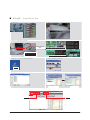
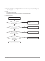
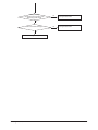
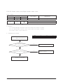
Ƶ Method#2 : Using Serial line
1) Power off
2) Take off the Cabinet : Check the LED off
3) Connect PC-Download Jig-PBA
Download connector
(10pin)
RS 232 to Serial
Download Converter
Download connector
(10pin,Black)
1)DB41-01010A : CN201
2)DB41-01129A : CN201
3)DB41-01023A : CN512
4)DB41-01081B : CN37
PIN# 1:RXD, 2:TXD, 9:GND, 10:VCC
Download connector
(20pin, Black)
1)DB41-01227A : CN201
2)DB41-01228A : CN201
PIN# 1:RXD, 2:TXD, 9:GND, 10:VCC
4) Execute the Inverter Download program
5) Select COM Port and connect
4) CLICK
6) Open the file(*.src)
7) Click the Start button
Waiting down load
Download
6) CLICK
7) CLICK
3-10
5) CLICK
Samsung Electronics
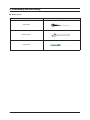
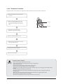
4. Disassembly and Reassembly
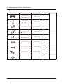
Q Necessary Tools
Item
Remark
+SCREW DRIVER
MONKEY SPANNER
- SCREW DRIVER
Samsung Electronics
4-1
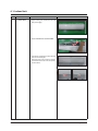
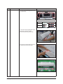
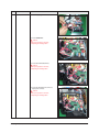
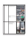
4-1. Indoor Unit
No
Parts
Procedure
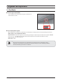
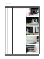
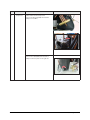
1
PANEL-FRONT
1) Stop the driving of air conditioner and shut off
main power supply.
Remark
2) Detach FILTER PRE from the PANEL FRONT.
3) Cover Panel is assembled on bottom of indoor
unit as shown in the figure.
Remove the Cap Screw as shown on the right
side and then remove the screw and separate
the Cover Panel.
4-2
Samsung Electronics
No
Parts
Procedure
Remark
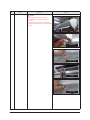
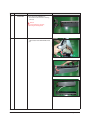
4) Cover Panel is fixed to body by Hook in center
area and side area.
Center area
Side area
Side area
HOOK
9/12K
18/24/30K
5) Separate the hook after pushing both end of
Cover Panel as shown in the figure.
(Watch out for the damage of the hook)
6) Raise front part upward obliquely as shown in
the figure and then remove the hooks.
Samsung Electronics
4-3
No
Parts
Procedure
Remark
Caution:
Assembly of Cover Panel after service end.
- Reassembly is in the reverse order of the
removal.
- Piping and drain hose must be careful not to
damage and Progress must be done with both
hands.
Hook (Side)
Hook (Center)
Screw
Cap Screw
4-4
Samsung Electronics
No
Parts
Procedure
Remark
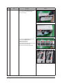
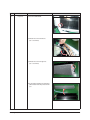
7) To detach the PANEL-FRONT from the main
frame, unfasten 2 screws at the bottom.
(use + Screw Driver)
8) To detach the COVER-PANEL from the main
frame, loosen 4 HOOK Structures.
When separate the hook :
Use the (-) screw Driver.
(-)Screw Driver Insert the hook and then pull the
hook as shown on the right side.
(Watch out for the damage of the hook)
Samsung Electronics
4-5
No
Parts
Procedure
Remark
9) Remove the Panel Frame from the Main
Frame as shown on the right side.
10) Remove the WIFI KIT connector.
WIFI KIT connector is located of Panel Front.
(For model with WIFI KIT)
4-6
Samsung Electronics
No
Parts
Procedure
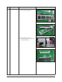
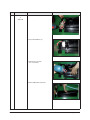
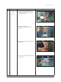
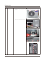
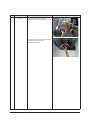
2
CONTORL IN
5) Loosen Stepping MOTOR Wire / BLADE Wire.
Remark
6) Loosen MOTOR Wire.
Caution:
When you separate the connector,
pull pressing the locking button.
7) Loosen the terminal block wires.
Caution:
When you separate the connector,
pull pressing the locking button.
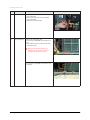
8) Loosen the Thermistor wire connector,
Display wire connector.
Caution:
When you separate the connector,
pull pressing the locking button.
Samsung Electronics
4-7
No
Parts
5
EVAPORATOR
Procedure
Remark
9) Take off the CASE-CONTROL from
the main frame after loosen the remaining
connector.
Caution:
When you separate the connector,
pull pressing the locking button.
3
4-8
TRAY DRAIN
1) To detach TRAY-DRAIN from the main frame,
pull the bottom of the TRAY-DRAIN towards
you.
Samsung Electronics
No
Parts
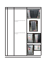
4
Evaporator
Procedure
Remark
1) Detach the HOLDER PIPE.
2) Unfasten the screw at the left side.
(use + Screw Driver)
3) Unfasten the screw at the right side.
(use + Screw Driver)
4) To detach Evaporator from the main frame,
pull the bottom of the Evaporator towards
you.
Samsung Electronics
4-9
No
Parts
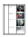
5
FAN MOTOR
&
CROSS FAN
Procedure
Remark
1) Unfasten the screw. (use + Screw Driver)
2) Detach the FAN Motor case.
3) Unfasten the screw a little.
(use + Screw Driver)
4) Pull the CROSS-FAN to the left side.
4-10
Samsung Electronics
No
Parts
6
Assy SPI Lamp
Procedure
Remark
1) Remove the Assy SPI Lamp from the Back
Body as shown on the right side.
Caution:
- Confirm Seal of backside necessarily after
replace of Assy SPI Lamp.
- Seal should be close adhesion to SPI Lamp.
- Measure as shown on the right side since
replace.
(If the seal is not close adhesion perfectly :
Defectiveness can happen)
Samsung Electronics
4-11
4-8
Samsung Electronics
%JTBTTFNCMZBOE3FBTTFNCMZ
/P
1BSUT
1SPDFEVSF
3FNBSL
-PPTFOGJYJOHTDSFXT$$8
PGUIF$BCJOFU
'SPOU
-PPTFOTDSFXT$$8
GJYFEPOUIF(VJEF
$POEFOTFS
Samsung Electronics
4-9
%JTBTTFNCMZBOE3FBTTFNCMZ
/P
1BSUT
'BO
.PUPS
1SPDFEVSF
3FNBSL
%FUBDIUIF/VU'MBOHFMJLFUIFQJDUVSFPO
UIFSJHIUTJEF5VSODMPDLXJTFCFDBVTFUIF
TDSFXJTMFGUIBOEFE
%FUBDIUIF'BO1SPQFMMFS
-PPTFOGJYJOHTDSFXT$$8
UPEFUBDI
UIF.PUPS
%JTDPOOFDUUIFXJSFCFUXFFO"TTZ$POUSPM
0VUBOE.PUPS
-PPTFOGJYJOHTDSFXT$$8
BOEEFUBDIUIF
#SBDLFU.PUPS
4-10
Samsung Electronics
%JTBTTFNCMZBOE3FBTTFNCMZ
/P
1BSUT
1SPDFEVSF
"TTZ$POUSPM0VU
%FUBDITFWFSBMDPOOFDUPSTGSPNUIF
"TTZ$POUSPM0VU
%FUBDITFWFSBMDPOOFDUPSTGSPNUIF1$#PG
"TTZ$POUSPM0VU
1VMMVQUIF"TTZ$POUSPM0VU
)FBU&YDIBOHFS
3FMFBTFUIFSFGSJHFSBOUBUGJSTU
-PPTFOGJYJOHTDSFX$$8
BOEEFUBDIUIFTUFFM
CBS
%JTBTTFNCMFUIFQJQFTJOCPUIJOMFUBOEPVUMFU
XJUIXFMEJOHUPSDL
3FNBSL
#FGPSFZPVEJTBTTFNCMFUIFQJQFTBOE
$POEFOTFSCFTVSFUIBUUIFSFTIPVMECF
OPSFGSJHFSBOUSFNBJOFEJOUIFVOJU
-PPTFOGJYJOHTDSFX$$8
BOEEFUBDIUIF)FBU
&YDIBOHFS
Samsung Electronics
4-11
/P
1BSUT
$PNQSFTTPS
1SPDFEVSF
3FNBSL
%JTBTTFNCMFUIF'FMU$PNQ4PVOE
-PPTFOUIFGJYJOHOVU$$8
BOEEFUBDIUIF
$PNQSFTTPS-FBE8JSF
-PPTFOUIFCPMUT$$8
BUUIFCPUUPNPG
$PNQSFTTPSMJLFUIFQJDUVSFPOUIFSJHIUTJEF
4-12
Samsung Electronics
Outdoor Unit
No
1
Parts
Proced ure
Common Work
1) Loosen each screws and detach the Cabi
Top Cover.
Rem ark
2) Loosen screws of the Cabi Front and detach it.
Samsung Electronics
4-17
No
Parts
Procedure
Remark
3) Loosen the 4 screws and detach the condbar.
4) Loosen fixing screws from the Cabi Front Lh
and detach it.
5) Loosen fixing screws from the Cabi Side Rh
and detach it.
4-18
Samsung Electronics
No
Parts
2
Fan
&
Motor
Procedure
Remark
1) Detach the Nut Flange like the picture on
the right side.(Turn clockwise because the
screw is left-handed.)
(Use Monkey Spanner.)
2) Detach the Fan Propeller.
3) Loosen 4 fixing screws to detach the Motor.
(Use Monkey Spanner.)
4) Disconnect the wire between Ass’y Control
Out and Motor.
5) Loosen 2 fixing bolts and detach the
Bracket Motor.(Use Monkey Spanner
Samsung Electronics
4-19
No
Parts
Procedure
3
Ass’y
Control Out
1) To remove the Cover control box : Pull the motor
wire is allow sufficient space as shown on the
right side and then remove the screw.
Remark
2) Detach several connectors from the Ass’y
Control Out.
3) Detach several connectors from the PCB of Ass’y
Control Out.
4
4-20
Heat Exchanger
1) Release the refrigerant at first.
2) Loosen fixing screw on both sides.
3) Disassemble the pipes in both inlet and
outlet with welding torch.
4) Detach the Heat Exchanger.
Samsung Electronics
No
Parts
Procedure
5
Compressor
1) Loosen the fixing nut and detach the
Compressor Lead Wire. (Use Monkey Spanner.)
Remark
2) Loosen the bolts at the bottom of Compressor
like the picture on the right side.
(Use Monkey Spanner.)
Samsung Electronics
4-21
5. Disassembly WIFI
5-1 WIFI Case
No
Parts
Procedure
1
CASE
Separate Case-WIFI Top
from Case-WIFI Button
2
BUTTON
Separate Case-WIFI Top
from Case-WIFI Button
Remark
Detach Assy Connector
Wire from Case-WIFI Button
3
WIRE
*Caution
When you separate the
connector , pull press
-ing the locking button
4
PBA
Separate PBA WIFI from
Case-WIFI Button
Samsung Electronics
5-1
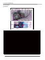
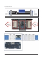
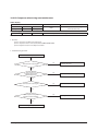
5-2 ASSY CONTROL IN
AR24HSFSRWKNER
AR24HSFNRWKNER
21
17
14
13
19
4
5
11
20
7
6
27
9
30
2
8
3
22
10
15
1
16
24
29
23
26
28
12
18
25
No
CODE
Des cr i pt i on
1
DB93-14236C
6002-000630
ASSY CONTROL I N
ASSY-SCREW TAPPING
2
DB93-14208A
3
DB90-07749B
4
DB93-14218A
5
DB68-02809A
6
DB92-02873A
7
DB92-02861A
8
DB93-14202A
9
DB95-05163A
ASSY CONNECTOR WIRE-DC
ASSY CASE CONTROL IN
ASSY CONNECTOR WIRE-DC
LABEL BAR CODE
ASSY PCB MAIN IN
ASSY MODULE
ASSY CONNECTOR WIRE-POWER
ASSY THERMISTOR IN
10
DB61-05891A
11
DB61-05963A
12
DB61-05961A
PLATE CONTROL-LEFT
13
DB62-11670A
SEAL CONTROL-A
CASE CONTROL IN
SUPPORT-CONTROL
Spec
Q'TY
1
PBA緖話
power-main(310V 19V)
2
1
1
F-05
Step-main(up)
1
LABEL BAR CODE
1
STD4
1
1
11W
1
main-power(SMPS IN)
1
sensor 1roomˈ2evap
F-05
1
case sub
1
PLATE CONTROL-LEFT
1
FLOCKED 52*65*T1 BLACK
1
14
DB62-11656C
15
DB63-03553C
SHEET-CONTROL
10x10xT0.07,AL SHEET
4
16
DB63-03553D
SHEET-CONTROL
22x22xT0.07,AL SHEET
1
17
DB65-00326A
TERMINAL BLOCK
TERMINAL BLOCK
1
18
DB61-05812A
PLATE CONTROL-SUB
19
DB93-14207A
20
DB93-14203A
21
DB93-14447A
ASSY CONNECTOR WIRE-COMM
22
DB93-14245A
ASSY CONNECTOR WIRE-EARTH
23
DB91-00309A
24
25
SEAL CUTT
PVC 52*30*T1 BLACK
0.052m
PLATE CONTROL-SUB
1
ASSY CONNECTOR WIRE-DC SIGNAL power-main(12V 5V)
ASSY CONNECTOR WIRE-POWER
T/B-main(power)
1
1
T/B-main(485)
1
ASSY CONNECTOR WIRE-EARTH
1
ASSY-SCREW TAPPING
M3,L25,ZPC(WHT),SWRCH18A
1
6002-000231
SCREW-TAPPING
M4,L12,ZPC(WHT),SWRCH18A
3
6009-001001
SCREW-SPECIAL
TH,M4,L10,ZPC(WHT),SWRCH18A
3
26
DB61-05871A
HOLDER-WIRE
HOLDER-WIRE
1
27
DB68-02809A
LABEL BAR CODE
1
28
DB98-33292A
ASSY-LABEL CAUTION
ASSY-LABEL CAUTION
1
29
DB98-33293A
ASSY-LABEL CAUTION
ASSY-LABEL CAUTION
1
30
DB71-50021A
WIRE-SADDLE
WIRE-SADDLE
1
5-2
LABEL BAR CODE
Samsung Electronics
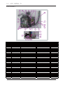
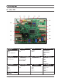
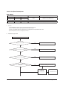
5-2 ASSY CONTROL IN
AR18(24)HSFNBWKNEU
AR18(24)HSFNBWKNEU
AR18HSFSRWKNER
AR18HSFNRWKNER
21
17
13
14
19
4
5
11
31
7
6
27
20
9
30
2
8
3
22
10
15
1
16
32
24
29
23
26
28
12
18
25
No
CODE
Des cr i pt i on
1
DB93-14236D
6002-000630
ASSY CONTROL I N
ASSY-SCREW TAPPING
2
DB93-14208A
3
DB90-07749B
4
DB93-14218A
5
DB68-02809A
6
DB92-02873A
7
DB92-02861A
8
DB93-14202A
9
DB95-05163A
ASSY CONNECTOR WIRE-DC
ASSY CASE CONTROL IN
ASSY CONNECTOR WIRE-DC
LABEL BAR CODE
ASSY PCB MAIN IN
ASSY MODULE
ASSY CONNECTOR WIRE-POWER
ASSY THERMISTOR IN
Spec
Q'TY
1
PBA緖話
power-main(310V 19V)
2
1
1
F-05
Step-main(up)
1
LABEL BAR CODE
1
STD4
1
1
11W
1
main-power(SMPS IN)
1
sensor 1roomˈ2evap
10
DB61-05891A
11
DB61-05963A
12
DB61-05961A
PLATE CONTROL-LEFT
13
DB62-11670A
SEAL CONTROL-A
14
DB62-11656C
15
DB63-03553C
SHEET-CONTROL
10x10xT0.07,AL SHEET
4
16
DB63-03553D
SHEET-CONTROL
22x22xT0.07,AL SHEET
1
17
DB65-00326A
TERMINAL BLOCK
18
DB61-05812A
PLATE CONTROL-SUB
19
DB93-14207A
20
DB93-14203A
21
DB93-14447A
ASSY CONNECTOR WIRE-COMM
22
DB93-14245A
ASSY CONNECTOR WIRE-EARTH
23
DB91-00309A
24
25
26
DB61-05871A
HOLDER-WIRE
27
DB68-02809A
LABEL BAR CODE
28
DB98-33292A
29
30
CASE CONTROL IN
SUPPORT-CONTROL
SEAL CUTT
F-05
1
case sub
1
PLATE CONTROL-LEFT
1
FLOCKED 52*65*T1 BLACK
1
PVC 52*30*T1 BLACK
0.052m
TERMINAL BLOCK
1
PLATE CONTROL-SUB
1
ASSY CONNECTOR WIRE-DC SIGNAL power-main(12V 5V)
ASSY CONNECTOR WIRE-POWER
T/B-main(power)
1
1
T/B-main(485)
1
ASSY CONNECTOR WIRE-EARTH
1
ASSY-SCREW TAPPING
M3,L25,ZPC(WHT),SWRCH18A
1
6002-000231
SCREW-TAPPING
M4,L12,ZPC(WHT),SWRCH18A
`
6009-001001
SCREW-SPECIAL
TH,M4,L10,ZPC(WHT),SWRCH18A
3
HOLDER-WIRE
1
LABEL BAR CODE
1
ASSY-LABEL CAUTION
ASSY-LABEL CAUTION
1
DB98-33293A
ASSY-LABEL CAUTION
ASSY-LABEL CAUTION
1
WIRE-SADDLE
WIRE-SADDLE
1
31
DB71-50021A
DB93-14221A
ASSY CONNECTOR WIRE-DC
FJM
1
32
DB93-14211A
ASSY CONNECTOR WIRE-DC
main-Wifi
1
5-2
Samsung Electronics
5-2
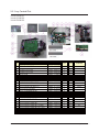
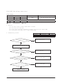
ASSY CONTROL IN
AR24FSFNAWKNFA
25
10
5
6
7
9
8
26
3
4
20
27
24
1
23
2
11
22
21
12
13
19
14
18
No
CODE
DB93-14235G
1
2
3
4
5
6
7
8
9
10
11
12
13
14
15
16
17
18
19
20
21
22
23
24
25
26
27
5-2
17
16
15
Description
ASSY CONTROL IN
Spec
Q'TY
10x10xT0.07,AL SHEET
DB63-03553C
DB61-05826A
Aluminum SHEET
CASE-CONTROL IN
CASE-CONTROL IN
DB93-14203A
POWER WIRE
T/B-main(power)
1
DB93-14245A
DB65-00326A
EARTH WIRE
TERMINAL BLOCK
EARTH WIRE
TERMINAL BLOCK
1
1
DB62-11656F
SEAL CUTT
PVC,BLACK,T1,W54
1
DB62-11680A
SEAL CONTROL
1
DB68-02809A
DB93-14447A
ASSY-LABEL
COMMUNICATION WIRE
FLOCKED,BLACK,T1,W50,54
ASSY-LABEL
T/B-main(485)
DB93-14207A
FUSE WIRE
power-main(12V 5V)
1
DB63-03553D
DB68-33293A
Aluminum SHEET
ASSY-LABEL
22x22xT0.07,AL SHEET
ASSY-LABEL
1
1
DB61-05807A
PLATE-CONTROL IN
F01
1
DB68-33292A
DB91-00309A
DB61-05812A
ASSY-LABEL
SCREW
PLATE
ASSY-LABEL
1
1
1
6009-001001
6002-000231
DB61-05871A
SCREW
SCREW
HOLDER-WIRE CLAMP
TH,M4,L10,ZPC(WHT),SWRCH18A嘅
M4,L12,ZPC(WHT),SWRCH18A嘅
HOLDER-WIRE CLAMP
3
2
1
DB92-02873A
DB92-02861A
MAIN PBA
POWER PBA
STD4
STD11W
1
1
DB71-50021A
DB93-14208A
DB95-05163A
WIRE-SADDLE
ASSY CONNECTOR WIRE-DC
ASSY THERMISTOR IN
WIRE-SADDLE
power-main(310V 19V)
sensor 1roomˈ2evap
1
1
1
DB93-14221A
DB93-14202A
DB93-14211A
ASSY CONNECTOR WIRE-DC
ASSY CONNECTOR WIRE-DC
ASSY CONNECTOR WIRE-DC
M3,L25,ZPC(WHT),SWRCH18A嘅
PLATE
FJM
main-power(SMPS IN)
main-Wifi
4
1
1
1
1
1
1
Samsung Electronics
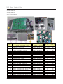
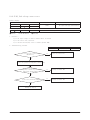
5-3 Assy Control Out
AR18HSFNBWKXEU
AR18HSFSRWKXER
AR18HSFNRWKXER
No
1
2
3
4
5
6
7
8
9
10
11
12
13
14
15
16
17
18
19
20
5-4
NAME
ASSYCONTROLOUT
GREASE-SILICON
SCREW-TAPPING
SCREW-TAPPING
HEATSINK
SEALCUTT
CABLETIE
LABELBARCODE
ASSYCASECONTROLOUT
ASSYCOVERCONTROL-UP
ASSYCASECONTROL
ASSY-SCREWMACHINE
ASSYPCBSUB
ASSYMODULE
ASSYPCBMAIN
ASSYCONNECTORWIRE
ASSYCONNECTORWIRE
ASSYCONNECTORWIRE-POWER
ASSYCONNECTORWIRE-DCSIGN
ASSYCONNECTORWIRE-DCSIGN
ASSYCONNECTORWIRE-DCSIGN
CODE
QTY UNIT
REMARK
DB93-14201D
0205-000178 0.002 KG
6002-000527
1
PC
6002-000536
1
PC
DB62-11646A
1
PC
DB62-11656B
0
M
DB65-10088B
1
PC W3.6*L150
DB68-02809A
1
PC
DB90-06308P
1
PC
DB90-07729A
1
PC
㒘ӊ
DB90-07833A
1
PC
DB91-00933A
4
PC
DB92-02836A
0
PC
DB92-02862A
1
PC
DB92-02866A
1
PC
DB93-09493C
1
PC
DB93-09497E
1
PC
DB93-14275A
1
PC
AC
DB93-14276A
1
PC
DB93-14277A
1
PC
DB93-14278A
0
PC
Samsung Electronics
5-3
Assy Control Out
AR24HSFSRWKXER
AR24HSFNRWKXER
AR24HSFNBWKXEU
AR24FSFNAWKXFA
AR18(24)HSSDBWKXEU
NO.
1
2
3
4
5
6
7
8
9
10
11
12
13
14
15
16
17
18
19
NAME
ASSY CONTROL OUT
GREASE-SILICON
SCREW-TAPPING
CASE CONTROL-UPPER
SUPPORT-HEAT SINK
CASE CONTROL
HEAT SINK
CABLE TIE
LABEL BAR CODE
ASSY CASE CONTROL OUT
ASSY-SCREW MACHINE
ASSY-SCREW MACHINE
ASSY MODULE
ASSY PCB MAIN
ASSY CONNECTOR WIRE-4W
ASSY CONNECTOR WIRE
ASSY CONNECTOR WIRE
ASSY CONNECTOR WIRE-P
ASSY CONNECTOR WIRE-D
ASSY CONNECTOR WIRE-D
Samsung Electronics
CODE
DB93-14373A
0205-000178
6002-000536
DB61-04910A
DB61-05790A
DB61-05917A
DB62-10653A
DB65-10088B
DB68-02809A
DB90-06309M
DB91-00933A
DB91-00933A
DB92-02862A
DB92-02867A
DB93-10821C
DB93-10987A
DB93-10988E
DB93-14275A
DB93-14276A
DB93-14277A
Q'TY
0.003
4
1
1
1
1
1
1
1
4
2
1
1
1
1
1
1
1
1
UNIT
KG
PC
PC
PC
PC
PC
PC
PC
PC
PC
PC
PC
PC
PC
PC
PC
PC
PC
PC
5-5
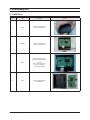
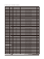
6. Electrical Parts List
6-1 INDOOR MAIN PCB (DB92-02873A)
Parts Code
0202-001338
0202-001463
0204-004665
0204-005794
0502-000245
1405-001239
2301-002032
2301-002032
3002-001139
3711-000177
3711-000203
3711-000296
3711-002001
3711-003404
3711-003845
3711-004122
3711-004236
3711-005096
3711-005097
3711-005504
DB27-00096A
DB67-00942A
DB94-04097A
0501-000362
1404-001194
3601-001765
3711-000024
3711-000941
3711-000998
3711-000999
DB94-04098A
0202-001459
0402-001741
0406-001204
0406-001204
0406-001204
0501-000465
0504-001080
0504-001080
0506-000175
0506-000175
0604-001002
0604-001002
0604-001002
0801-000393
1006-001325
1202-000104
1203-006245
1203-007526
2007-000029
2007-000029
2007-000067
2007-000072
2007-000076
2007-000076
2007-000076
2007-000078
2007-000078
Samsung Electronics
Design Loc
SOLDER-BAR
SOLDER-WIRE
FLUX
SOLVENT
Q701
VA71
XC71
XC72
BZ61
CN21
CN75
CN72
CN31
CN71
CN91
CN32
CN43
CN63
CN62
CN51
FT71
VA71-1
Q801
PTC2
F701
CN76
CN81
CN77
CN61
SOLDER-CREAM
D701
CD81
CD82
CD83
Q702
Q601
Q802
IC05
IC06
PC03
PC04
PC05
IC08
IC07
IC11
IC03
IC02
R850
R851
R713
R717
R601
R602
R716
R703
R706
Parts Description
SOLDER-BAR
SOLDER-WIRE
FLUX
SOLVENT
TR-POWER
VARISTOR
C-FILM,LEAD-PPF
C-FILM,LEAD-PPF
BUZZER-PIEZO
HEADER-BOARD TO CABLE
HEADER-BOARD TO CABLE
HEADER-BOARD TO CABLE
HEADER-BOARD TO CABLE
HEADER-BOARD TO CABLE
HEADER-BOARD TO CABLE
HEADER-BOARD TO CABLE
HEADER-BOARD TO CABLE
HEADER-BOARD TO CABLE
HEADER-BOARD TO CABLE
HEADER-BOARD TO CABLE
COIL CHOKE
CAP
ASSY PCB AUTO
TR-SMALL SIGNAL
THERMISTOR-PTC
FUSE-ETC
HEADER-BOARD TO CABLE
HEADER-BOARD TO CABLE
CONNECTOR-HEADER
HEADER-BOARD TO CABLE
ASSY PCB SMD
SOLDER-CREAM
DIODE-RECTIFIER
DIODE-TVS
DIODE-TVS
DIODE-TVS
TR-SMALL SIGNAL
TR-DIGITAL
TR-DIGITAL
TR-ARRAY
TR-ARRAY
PHOTO-COUPLER
PHOTO-COUPLER
PHOTO-COUPLER
IC-CMOS LOGIC
IC-BUS TRANSCEIVER
IC-VOLTAGE COMP.
IC-VOL. DETECTOR
IC-POSI.FIXED REG.
R-CHIP
R-CHIP
R-CHIP
R-CHIP
R-CHIP
R-CHIP
R-CHIP
R-CHIP
R-CHIP
Quantity
0.17
1.51
0.14
1
1
1
1
1
1
1
1
1
1
1
1
1
1
1
1
1
1
1
1
1
1
1
1
1
1
1
1
0.32
1
1
1
1
1
1
1
1
1
1
1
1
1
1
1
1
1
1
1
1
1
1
1
1
1
1
6-1
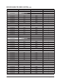
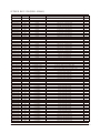
INDOOR MAIN PCB (DB92-02873A) cont.
Parts Code
2007-000078
2007-000078
2007-000084
2007-000087
2007-000090
2007-000090
2007-000090
2007-000090
2007-000090
2007-000090
2007-000090
2007-000090
2007-000090
2007-000116
2007-000130
2007-000138
2007-000138
2007-000138
2007-000138
2007-000138
2007-000138
2007-000138
2007-000138
2007-000138
2007-000138
2007-000140
2007-000140
2007-000140
2007-000140
2007-000143
2007-000143
2007-000143
2007-000148
2007-000148
2007-000148
2007-000148
2007-000148
2007-000148
2007-000148
2007-000148
2007-000148
2007-000148
2007-000148
2007-000148
2007-000148
2007-000148
2007-000148
2007-000148
2007-000148
2007-000148
2007-000148
2007-000148
2007-000148
2007-000148
2007-000148
2007-000148
2007-000148
2007-000148
2007-000148
2007-000148
6-2
Design Loc
R805
R815
R707
R708
R701
R704
R705
R723
R801
R802
R803
R804
R816
R825
R715
R508
R515
R516
R517
R518
R519
R520
R539
R542
R809
R538
R545
R806
R901
R511
R512
R513
R502
R503
R504
R505
R506
R507
R510
R521
R522
R523
R524
R525
R526
R527
R528
R529
R530
R531
R532
R533
R534
R543
R544
R807
R808
R810
R824
R903
Parts Description
R-CHIP
R-CHIP
R-CHIP
R-CHIP
R-CHIP
R-CHIP
R-CHIP
R-CHIP
R-CHIP
R-CHIP
R-CHIP
R-CHIP
R-CHIP
R-CHIP
R-CHIP
R-CHIP
R-CHIP
R-CHIP
R-CHIP
R-CHIP
R-CHIP
R-CHIP
R-CHIP
R-CHIP
R-CHIP
R-CHIP
R-CHIP
R-CHIP
R-CHIP
R-CHIP
R-CHIP
R-CHIP
R-CHIP
R-CHIP
R-CHIP
R-CHIP
R-CHIP
R-CHIP
R-CHIP
R-CHIP
R-CHIP
R-CHIP
R-CHIP
R-CHIP
R-CHIP
R-CHIP
R-CHIP
R-CHIP
R-CHIP
R-CHIP
R-CHIP
R-CHIP
R-CHIP
R-CHIP
R-CHIP
R-CHIP
R-CHIP
R-CHIP
R-CHIP
R-CHIP
Quantity
1
1
1
1
1
1
1
1
1
1
1
1
1
1
1
1
1
1
1
1
1
1
1
1
1
1
1
1
1
1
1
1
1
1
1
1
1
1
1
1
1
1
1
1
1
1
1
1
1
1
1
1
1
1
1
1
1
1
1
1
Samsung Electronics
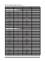
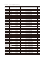
INDOOR MAIN PCB (DB92-02873A) cont.
Parts Code
2007-000148
2007-000157
2007-000162
2007-000162
2007-000171
2007-000171
2007-000171
2007-000171
2007-000171
2007-000171
2007-000303
2007-000385
2007-000455
2007-000475
2007-000924
2007-000924
2007-000924
2007-000939
2007-001096
2007-001313
2007-001313
2007-001313
2007-001313
2007-001313
2007-001433
2007-007313
2007-007313
2007-007313
2007-009922
2007-009922
2007-009922
2203-000257
2203-000257
2203-000438
2203-000438
2203-000438
2203-000438
2203-000440
2203-000440
2203-001071
2203-005249
2203-005249
2203-005249
2203-005249
2203-005249
2203-005249
2203-005249
2203-005249
2203-005249
2203-005249
2203-005249
2203-005249
2203-005249
2203-005249
2203-005249
2203-005249
2203-005249
2203-005249
2203-005249
2203-005249
Samsung Electronics
Design Loc
R904
R902
R820
R821
R831
R833
R835
R837
R839
R843
R702
R115
R712
R709
R112
R113
R114
R711
R714
R404
R405
R406
R410
R811
R618
R401
R402
R403
R301
R302
R303
C705
C801
C508
C516
C520
C901
C711
C715
C519
C401
C402
C403
C511
C513
C514
C517
C522
C529
C530
C531
C533
C702
C704
C710
C712
C713
C802
C803
C805
Parts Description
R-CHIP
R-CHIP
R-CHIP
R-CHIP
R-CHIP
R-CHIP
R-CHIP
R-CHIP
R-CHIP
R-CHIP
R-CHIP
R-CHIP
R-CHIP
R-CHIP
R-CHIP
R-CHIP
R-CHIP
R-CHIP
R-CHIP
R-CHIP
R-CHIP
R-CHIP
R-CHIP
R-CHIP
R-CHIP
R-CHIP
R-CHIP
R-CHIP
R-CHIP
R-CHIP
R-CHIP
C-CER,CHIP
C-CER,CHIP
C-CER,CHIP
C-CER,CHIP
C-CER,CHIP
C-CER,CHIP
C-CER,CHIP
C-CER,CHIP
C-CER,CHIP
C-CER,CHIP
C-CER,CHIP
C-CER,CHIP
C-CER,CHIP
C-CER,CHIP
C-CER,CHIP
C-CER,CHIP
C-CER,CHIP
C-CER,CHIP
C-CER,CHIP
C-CER,CHIP
C-CER,CHIP
C-CER,CHIP
C-CER,CHIP
C-CER,CHIP
C-CER,CHIP
C-CER,CHIP
C-CER,CHIP
C-CER,CHIP
C-CER,CHIP
Quantity
1
1
1
1
1
1
1
1
1
1
1
1
1
1
1
1
1
1
1
1
1
1
1
1
1
1
1
1
1
1
1
1
1
1
1
1
1
1
1
1
1
1
1
1
1
1
1
1
1
1
1
1
1
1
1
1
1
1
1
1
6-3
INDOOR MAIN PCB (DB92-02873A) cont.
Parts Code
2203-005249
2203-005249
2203-005249
2203-006496
2203-006960
2203-007486
2203-007486
2203-007486
2203-007486
2203-007486
2203-007486
2203-007486
2203-007486
2203-007486
2203-007486
2203-007486
2203-007486
2402-000120
2402-001145
2402-001145
2802-001211
DB41-01221A
DB91-01550A
0903-001864
DB98-31449A
DC68-02310A
6-4
Design Loc
C806
C807
C809
C707
C708
C509
C512
C515
C518
C521
C523
C526
C528
C551
C552
C804
C808
C706
C701
C703
X501
PCB MAIN
IC04
ASSY-LABEL MICOM
LABEL-BAR CODE
Parts Description
C-CER,CHIP
C-CER,CHIP
C-CER,CHIP
C-CER,CHIP
C-CER,CHIP
C-CER,CHIP
C-CER,CHIP
C-CER,CHIP
C-CER,CHIP
C-CER,CHIP
C-CER,CHIP
C-CER,CHIP
C-CER,CHIP
C-CER,CHIP
C-CER,CHIP
C-CER,CHIP
C-CER,CHIP
C-AL,SMD
C-AL,SMD
C-AL,SMD
RESONATOR-CERAMIC
PCB MAIN
ASSY MICOM
IC-MICROCONTROLLER
ASSY-LABEL MICOM
LABEL-BAR CODE
Quantity
1
1
1
1
1
1
1
1
1
1
1
1
1
1
1
1
1
1
1
1
1
1
1
1
1
1
Samsung Electronics
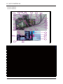
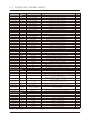
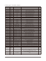
6-2
OUTDOOR MAIN PBA(DB92-02866A)
P arts C o d e
D esig n Lo c
D escrip tio n
0401-001099
0401-001099
0401-001099
0401-001099
0401-001099
0401-001099
0401-001099
0401-001099
0401-001099
0401-001099
0401-001099
0401-001099
0401-001099
0401-001099
0401-001099
0401-001099
0402-001795
0403-001499
0403-001499
0404-001020
0404-001020
0406-001204
0406-001204
0406-001204
0501-000465
0504-001008
0504-001008
0504-001008
0504-001008
0504-001044
0504-001080
0506-000175
0506-000175
0506-000175
0601-002423
0601-002955
0601-002956
0601-002956
0604-001172
0604-001172
0604-001172
D020
D021
D030
D152
D153
D454
D500
D501
D502
D503
D504
D505
D507
D508
D904
D905
D 903
ZD401
ZD420
D 491
D 492
TD 301
TD 302
TD 303
Q551
Q351
Q352
Q901
Q903
Q151
Q902
IC 061
IC 701
IC 702
LED801
LED803
LED551
LED802
P C 151
P C 351
P C 352
DIODE-SWITCHING
DIODE-SWITCHING
DIODE-SWITCHING
DIODE-SWITCHING
DIODE-SWITCHING
DIODE-SWITCHING
DIODE-SWITCHING
DIODE-SWITCHING
DIODE-SWITCHING
DIODE-SWITCHING
DIODE-SWITCHING
DIODE-SWITCHING
DIODE-SWITCHING
DIODE-SWITCHING
DIODE-SWITCHING
DIODE-SWITCHING
D IO D E-REC TIFIER
DIODE-ZENER
DIODE-ZENER
D IO D E-SC H O TTKY
D IO D E-SC H O TTKY
D IO D E-TV S
D IO D E-TV S
D IO D E-TV S
TR-SMALL SIGNAL
TR-DIGITAL
TR-DIGITAL
TR-DIGITAL
TR-DIGITAL
TR-DIGITAL
TR-DIGITAL
TR-A RRAY
TR-A RRAY
TR-A RRAY
LED
LED
LED
LED
PH O TO -C O U PLER
PH O TO -C O U PLER
PH O TO -C O U PLER
0801-000393
IC302
IC-CMOS LOGIC
1006-001325
IC301
IC-BUS TRANSCEIVER
1201-002946
IC451
IC-OP AMP
1203-002835
1203-002986
IC154
IC155
1203-004967
IC502
1404-001498
1405-000154
1405-000154
1405-001239
1405-001239
2007-000043
2007-000070
2007-000074
2007-000074
2007-000074
2007-000074
2007-000074
2007-000074
PTC 020
VA002
VA003
VA001
VA401
R 424
R 309
R 152
R 210
R 213
R 233
R 234
R 401
Samsung Electronics
IC-POSI.FIXED REG.
IC-POSI.FIXED REG.
IC-VOL. DETECTOR
TH ERM ISTO R-PTC
VARISTOR
VARISTOR
VARISTOR
VARISTOR
R-C H IP
R-C H IP
R-C H IP
R-C H IP
R-C H IP
R-C H IP
R-C H IP
R-C H IP
S p ec.
1N4148WS,75V,150mA,SOD-323,TP
1N4148WS,75V,150mA,SOD-323,TP
1N4148WS,75V,150mA,SOD-323,TP
1N4148WS,75V,150mA,SOD-323,TP
1N4148WS,75V,150mA,SOD-323,TP
1N4148WS,75V,150mA,SOD-323,TP
1N4148WS,75V,150mA,SOD-323,TP
1N4148WS,75V,150mA,SOD-323,TP
1N4148WS,75V,150mA,SOD-323,TP
1N4148WS,75V,150mA,SOD-323,TP
1N4148WS,75V,150mA,SOD-323,TP
1N4148WS,75V,150mA,SOD-323,TP
1N4148WS,75V,150mA,SOD-323,TP
1N4148WS,75V,150mA,SOD-323,TP
1N4148WS,75V,150mA,SOD-323,TP
1N4148WS,75V,150mA,SOD-323,TP
U S1M ,1000V,1A ,SM A ,TP
MMSZ5252B,22.8/25.2V,500mW,SOD-123,TP
MMSZ5252B,22.8/25.2V,500mW,SOD-123,TP
B AT54C ,30V,200m A ,SO T-23,TP
B AT54C ,30V,200m A ,SO T-23,TP
SM B J5.0C A ,6.4/-/7.25V,600W ,SM B
SM B J5.0C A ,6.4/-/7.25V,600W ,SM B
SM B J5.0C A ,6.4/-/7.25V,600W ,SM B
MMBT3904,NPN,350mW,SOT-23,TP,30-300
RN2427,PNP,200mW,2.2K/10Kohm,SOT-23,TP
RN2427,PNP,200mW,2.2K/10Kohm,SOT-23,TP
RN2427,PNP,200mW,2.2K/10Kohm,SOT-23,TP
RN2427,PNP,200mW,2.2K/10Kohm,SOT-23,TP
KRA226M,PNP,400MW,2.2K/10K,TO-92M,TP
KRC246S,NPN,200mW,2.2K/10Kohm,SOT-23,TP
2003,N PN ,7,1W ,SO P-16,ST,1000
2003,N PN ,7,1W ,SO P-16,ST,1000
2003,N PN ,7,1W ,SO P-16,ST,1000
SMD(REVERSE),RED,3.2x1.6mm,639nm,3.2x1.6x1.1mm
SMD(REVERSE),YEL,1.6x1.5mm,588nm,3.2x1.6x1.1mm
SMD(REVERSE),GRN,1.6x1.5mm,3.2x1.6x1.1mm
SMD(REVERSE),GRN,1.6x1.5mm,3.2x1.6x1.1mm
TR,150-300,200m W ,SO P,TP
TR,150-300,200m W ,SO P,TP
TR,150-300,200m W ,SO P,TP
74HC86,OR GATE,SOP,14P,150MIL,QUAD,ST,-,2.0/6.0V,0.26V,40to+85C,180mW,4.2V,1uA,
ISL81487LIBZ,SO,8P,4.9x3.8 mm,SINGLE,ST,PLASTIC,5V,40to+85C,520mW,1,1,1.5/5.0V
TSSOP,TR,14P,5x4.4x1.2mm,100,5.5V,40to+85C,63dB,1,1nA,1nA,1.7mV
7805,3P,6.6x6.1mm,PLASTIC,4.8V/5.2V,1.3W,-40to+85,1A,TP
7812,3P,6.6x6.1mm,PLASTIC,11.5/12.5V,1.3,150C,1A,TP
KIA7042AT,TSM,3P,2.9x1.6mm,PLASTIC,4.2V,350mW,30to+75C,20mA,-,40o h m ,25% ,290Vac,7A ,TR
560V,460Vdc,4500A,17.5x7.5mm,BK,920V,600pF
560V,460Vdc,4500A,17.5x7.5mm,BK,920V,600pF
680V,560Vdc,6000A,17x7.3mm,BK,1120V,350pF
680V,560Vdc,6000A,17x7.3mm,BK,1120V,350pF
1K o h m ,1% ,1/10W ,TP,1608
0o h m ,5% ,1/10W ,TP,1608
100o h m ,5% ,1/10W ,TP,1608
100o h m ,5% ,1/10W ,TP,1608
100o h m ,5% ,1/10W ,TP,1608
100o h m ,5% ,1/10W ,TP,1608
100o h m ,5% ,1/10W ,TP,1608
100o h m ,5% ,1/10W ,TP,1608
Q'TY
1
1
1
1
1
1
1
1
1
1
1
1
1
1
1
1
1
1
1
1
1
1
1
1
1
1
1
1
1
1
1
1
1
1
1
1
1
1
1
1
1
1
1
1
1
1
1
1
1
1
1
1
1
1
1
1
1
1
1
1
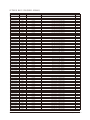
6-5
OUTDOOR MAIN PBA(DB92-02866A)
P arts C o d e
D esig n Lo c
D escrip tio n
S p ec.
Q'TY
2007-000074
2007-000074
2007-000074
2007-000074
2007-000074
2007-000074
2007-000074
2007-000074
2007-000074
2007-000074
2007-000074
2007-000076
2007-000076
2007-000076
2007-000076
2007-000076
2007-000076
2007-000076
2007-000076
2007-000076
2007-000076
2007-000078
2007-000078
2007-000078
2007-000078
2007-000078
2007-000078
2007-000078
2007-000078
2007-000078
2007-000078
2007-000078
2007-000078
2007-000078
2007-000078
2007-000078
2007-000078
2007-000078
2007-000078
2007-000080
2007-000082
2007-000084
2007-000084
2007-000084
2007-000084
2007-000084
2007-000084
2007-000084
2007-000084
2007-000084
2007-000084
2007-000084
2007-000084
2007-000084
2007-000084
2007-000084
2007-000084
2007-000084
2007-000084
2007-000084
2007-000084
2007-000084
2007-000084
2007-000084
R 402
R 403
R 404
R 405
R 406
R 407
R 4 20
R 422
R 516
R 519
R 562
R 153
R 255
R 256
R 257
R 25 8
R 352
R 353
R 512
R 567
R 904
R 303
R 307
R 308
R 351
R 354
R 503
R 504
R 505
R 508
R 509
R 515
R 529
R 530
R 556
R 557
R 558
R 560
R 563
R 522
R 421
R 211
R 212
R 214
R 215
R 216
R 217
R 218
R 219
R 220
R 408
R 501
R 506
R 507
R 510
R 511
R 517
R 518
R 520
R 521
R 523
R 524
R 525
R 526
R-C H IP
R-C H IP
R-C H IP
R-C H IP
R-C H IP
R-C H IP
R-C H IP
R-C H IP
R-C H IP
R-C H IP
R-C H IP
R-C H IP
R-C H IP
R-C H IP
R-C H IP
R-C H IP
R-C H IP
R-C H IP
R-C H IP
R-C H IP
R-C H IP
R-C H IP
R-C H IP
R-C H IP
R-C H IP
R-C H IP
R-C H IP
R-C H IP
R-C H IP
R-C H IP
R-C H IP
R-C H IP
R-C H IP
R-C H IP
R-C H IP
R-C H IP
R-C H IP
R-C H IP
R-C H IP
R-C H IP
R-C H IP
R-C H IP
R-C H IP
R-C H IP
R-C H IP
R-C H IP
R-C H IP
R-C H IP
R-C H IP
R-C H IP
R-C H IP
R-C H IP
R-C H IP
R-C H IP
R-C H IP
R-C H IP
R-C H IP
R-C H IP
R-C H IP
R-C H IP
R-C H IP
R-C H IP
R-C H IP
R-C H IP
100o h m ,5% ,1/10W ,TP,1608
100o h m ,5% ,1/10W ,TP,1608
100o h m ,5% ,1/10W ,TP,1608
100o h m ,5% ,1/10W ,TP,1608
100o h m ,5% ,1/10W ,TP,1608
100o h m ,5% ,1/10W ,TP,1608
100o h m ,5% ,1/10W ,TP,1608
100o h m ,5% ,1/10W ,TP,1608
100o h m ,5% ,1/10W ,TP,1608
100o h m ,5% ,1/10W ,TP,1608
100o h m ,5% ,1/10W ,TP,1608
330o h m ,5% ,1/10W ,TP,1608
330o h m ,5% ,1/10W ,TP,1608
330o h m ,5% ,1/10W ,TP,1608
330o h m ,5% ,1/10W ,TP,1608
330o h m ,5% ,1/10W ,TP,1608
330o h m ,5% ,1/10W ,TP,1608
330o h m ,5% ,1/10W ,TP,1608
330o h m ,5% ,1/10W ,TP,1608
330o h m ,5% ,1/10W ,TP,1608
330o h m ,5% ,1/10W ,TP,1608
1K o h m ,5% ,1/10W ,TP,1608
1K o h m ,5% ,1/10W ,TP,1608
1K o h m ,5% ,1/10W ,TP,1608
1K o h m ,5% ,1/10W ,TP,1608
1K o h m ,5% ,1/10W ,TP,1608
1K o h m ,5% ,1/10W ,TP,1608
1K o h m ,5% ,1/10W ,TP,1608
1K o h m ,5% ,1/10W ,TP,1608
1K o h m ,5% ,1/10W ,TP,1608
1K o h m ,5% ,1/10W ,TP,1608
1K o h m ,5% ,1/10W ,TP,1608
1K o h m ,5% ,1/10W ,TP,1608
1K o h m ,5% ,1/10W ,TP,1608
1K o h m ,5% ,1/10W ,TP,1608
1K o h m ,5% ,1/10W ,TP,1608
1K o h m ,5% ,1/10W ,TP,1608
1K o h m ,5% ,1/10W ,TP,1608
1K o h m ,5% ,1/10W ,TP,1608
2K o h m ,5% ,1/10W ,TP,1608
3.3K o h m ,5% ,1/10W ,TP,1608
4.7K o h m ,5% ,1/10W ,TP,1608
4.7K o h m ,5% ,1/10W ,TP,1608
4.7K o h m ,5% ,1/10W ,TP,1608
4.7K o h m ,5% ,1/10W ,TP,1608
4.7K o h m ,5% ,1/10W ,TP,1608
4.7K o h m ,5% ,1/10W ,TP,1608
4.7K o h m ,5% ,1/10W ,TP,1608
4.7K o h m ,5% ,1/10W ,TP,1608
4.7K o h m ,5% ,1/10W ,TP,1608
4.7K o h m ,5% ,1/10W ,TP,1608
4.7K o h m ,5% ,1/10W ,TP,1608
4.7K o h m ,5% ,1/10W ,TP,1608
4.7K o h m ,5% ,1/10W ,TP,1608
4.7K o h m ,5% ,1/10W ,TP,1608
4.7K o h m ,5% ,1/10W ,TP,1608
4.7K o h m ,5% ,1/10W ,TP,1608
4.7K o h m ,5% ,1/10W ,TP,1608
4.7K o h m ,5% ,1/10W ,TP,1608
4.7K o h m ,5% ,1/10W ,TP,1608
4.7K o h m ,5% ,1/10W ,TP,1608
4.7K o h m ,5% ,1/10W ,TP,1608
4.7K o h m ,5% ,1/10W ,TP,1608
4.7K o h m ,5% ,1/10W ,TP,1608
1
1
1
1
1
1
1
1
1
1
1
1
1
1
1
1
1
1
1
1
1
1
1
1
1
1
1
1
1
1
1
1
1
1
1
1
1
1
1
1
1
1
1
1
1
1
1
1
1
1
1
1
1
1
1
1
1
1
1
1
1
1
1
1
6-6
Samsung Electronics
OUTDOOR MAIN PBA(DB92-02866A)
P arts C o d e
D esig n Lo c
D escrip tio n
S p ec.
Q'TY
2007-000084
2007-000084
2007-000084
2007-000084
2007-000084
2007-000090
2007-000090
2007-000090
2007-000090
2007-000090
2007-000090
2007-000090
2007-000090
2007-000090
2007-000090
2007-000090
2007-000090
2007-000090
2007-000090
2007-000109
2007-000116
2007-000124
2007-000140
2007-000140
2007-000143
2007-000143
2007-000143
2007-000143
2007-000143
2007-000143
2007-000143
2007-000143
2007-000143
2007-000143
2007-000143
2007-000143
2007-000143
2007-000148
2007-000148
2007-000148
2007-000170
2007-000239
2007-000256
2007-000256
2007-000256
2007-000300
2007-000385
2007-000385
2007-000455
2007-000455
2007-000491
2007-000536
2007-000537
2007-000537
2007-000537
2007-000537
2007-000537
2007-000614
2007-000614
2007-000614
2007-000614
2007-000614
2007-000614
2007-000614
R 527
R 534
R 535
R 536
R 903
R 301
R 302
R 304
R 305
R 528
R 532
R 533
R 551
R 552
R 553
R 554
R 555
R 559
R 565
R 531
R 306
R 564
R 202
R 205
R 207
R 221
R 222
R 223
R 224
R 225
R 226
R 227
R 228
R 229
R 230
R 231
R 232
R 203
R 204
R 206
R 201
R 491
R 455
R 457
R 468
R 901
R 10 1
R 105
R 251
R 253
R 561
R 492
R 154
R 155
R 156
R 1 57
R 158
R 252
R 254
R 469
R 470
R 471
R 472
R 473
R-C H IP
R-C H IP
R-C H IP
R-C H IP
R-C H IP
R-C H IP
R-C H IP
R-C H IP
R-C H IP
R-C H IP
R-C H IP
R-C H IP
R-C H IP
R-C H IP
R-C H IP
R-C H IP
R-C H IP
R-C H IP
R-C H IP
R-C H IP
R-C H IP
R-C H IP
R-C H IP
R-C H IP
R-C H IP
R-C H IP
R-C H IP
R-C H IP
R-C H IP
R-C H IP
R-C H IP
R-C H IP
R-C H IP
R-C H IP
R-C H IP
R-C H IP
R-C H IP
R-C H IP
R-C H IP
R-C H IP
R-C H IP
R-C H IP
R-C H IP
R-C H IP
R-C H IP
R-C H IP
R-C H IP
R-C H IP
R-C H IP
R-C H IP
R-C H IP
R-C H IP
R-C H IP
R-C H IP
R-C H IP
R-C H IP
R-C H IP
R-C H IP
R-C H IP
R-C H IP
R-C H IP
R-C H IP
R-C H IP
R-C H IP
4.7K o h m ,5% ,1/10W ,TP,1608
4.7K o h m ,5% ,1/10W ,TP,1608
4.7K o h m ,5% ,1/10W ,TP,1608
4.7K o h m ,5% ,1/10W ,TP,1608
4.7K o h m ,5% ,1/10W ,TP,1608
10K o h m ,5% ,1/10W ,TP,1608
10K o h m ,5% ,1/10W ,TP,1608
10K o h m ,5% ,1/10W ,TP,1608
10K o h m ,5% ,1/10W ,TP,1608
10K o h m ,5% ,1/10W ,TP,1608
10K o h m ,5% ,1/10W ,TP,1608
10K o h m ,5% ,1/10W ,TP,1608
10K o h m ,5% ,1/10W ,TP,1608
10K o h m ,5% ,1/10W ,TP,1608
10K o h m ,5% ,1/10W ,TP,1608
10K o h m ,5% ,1/10W ,TP,1608
10K o h m ,5% ,1/10W ,TP,1608
10K o h m ,5% ,1/10W ,TP,1608
10K o h m ,5% ,1/10W ,TP,1608
1M o h m ,5% ,1/10W ,TP,1608
120o h m ,5% ,1/10W ,TP,1608
2.2K o h m ,5% ,1/10W ,TP,1608
1K o h m ,5% ,1/16W ,TP,1005
1K o h m ,5% ,1/16W ,TP,1005
4.7K o h m ,5% ,1/16W ,TP,1005
4.7K o h m ,5% ,1/16W ,TP,1005
4.7K o h m ,5% ,1/16W ,TP,1005
4.7K o h m ,5% ,1/16W ,TP,1005
4.7K o h m ,5% ,1/16W ,TP,1005
4.7K o h m ,5% ,1/16W ,TP,1005
4.7K o h m ,5% ,1/16W ,TP,1005
4.7K o h m ,5% ,1/16W ,TP,1005
4.7K o h m ,5% ,1/16W ,TP,1005
4.7K o h m ,5% ,1/16W ,TP,1005
4.7K o h m ,5% ,1/16W ,TP,1005
4.7K o h m ,5% ,1/16W ,TP,1005
4.7K o h m ,5% ,1/16W ,TP,1005
10K o h m ,5% ,1/16W ,TP,1005
10K o h m ,5% ,1/16W ,TP,1005
10K o h m ,5% ,1/16W ,TP,1005
1M o h m ,5% ,1/16W ,TP,1005
1.5K o h m ,1% ,1/10W ,TP,1608
1.6K o h m ,1% ,1/10W ,TP,1608
1.6K o h m ,1% ,1/10W ,TP,1608
1.6K o h m ,1% ,1/10W ,TP,1608
10K o h m ,5% ,1/8W ,TP,2012
14.3K o h m ,1% ,1/4W ,TP,3216
14.3K o h m ,1% ,1/4W ,TP,3216
18K o h m ,1% ,1/10W ,TP,1608
18K o h m ,1% ,1/10W ,TP,1608
2.2K o h m ,1% ,1/10W ,TP,1608
200o h m ,1% ,1/10W ,TP,1608
200o h m ,1% ,1/4W ,TP,3216
200o h m ,1% ,1/4W ,TP,3216
200o h m ,1% ,1/4W ,TP,3216
200o h m ,1% ,1/4W ,TP,3216
200o h m ,1% ,1/4W ,TP,3216
24K o h m ,1% ,1/10W ,TP,1608
24K o h m ,1% ,1/10W ,TP,1608
24K o h m ,1% ,1/10W ,TP,1608
24K o h m ,1% ,1/10W ,TP,1608
24K o h m ,1% ,1/10W ,TP,1608
24K o h m ,1% ,1/10W ,TP,1608
24K o h m ,1% ,1/10W ,TP,1608
1
1
1
1
1
1
1
1
1
1
1
1
1
1
1
1
1
1
1
1
1
1
1
1
1
1
1
1
1
1
1
1
1
1
1
1
1
1
1
1
1
1
1
1
1
1
1
1
1
1
1
1
1
1
1
1
1
1
1
1
1
1
1
1
Samsung Electronics
6-7
OUTDOOR MAIN PBA(DB92-02866A)
P arts C o d e
D esig n Lo c
D escrip tio n
2007-000614
2007-000651
2007-000683
2007-000683
2007-000683
2007-000763
2007-000763
2007-000872
2007-000872
2007-000872
2007-000924
2007-000924
2007-000924
2007-000924
2007-000924
2007-000924
2007-000979
2007-001071
2007-001175
2007-001175
2007-001175
2007-010245
2007-010245
2007-010245
2007-010245
2007-010245
2201-000540
2201-002002
2201-002002
2201-002002
2201-002002
2201-002427
2203-000236
2203-000257
2203-000257
2203-000257
2203-000257
2203-000257
2203-000257
2203-000257
2203-000257
2203-000257
2203-000440
2203-000440
2203-000440
2203-000440
2203-000440
2203-000440
2203-000440
2203-000440
2203-000440
2203-000440
2203-000440
2203-000440
2203-000440
2203-000440
2203-000440
2203-000440
2203-000440
2203-000783
2203-000783
2203-002002
2203-002002
2203-002002
R 474
R 475
R 454
R 459
R 466
R 476
R 477
R 801
R 802
R 803
R 102
R 103
R 104
R 106
R 107
R 108
R 478
R 902
R 409
R 423
R 427
R 410
R 411
R 412
R 42 5
R 426
C425
C004
C005
C012
C013
C901
C 421
C 222
C 223
C 224
C 225
C 301
C 351
C 352
C 422
C 423
C 404
C 405
C 406
C 408
C 409
C 410
C 411
C 501
C 504
C 505
C 506
C 507
C 508
C 510
C 512
C 523
C 904
C 455
C 458
C 453
C 454
C 459
R-C H IP
R-C H IP
R-C H IP
R-C H IP
R-C H IP
R-C H IP
R-C H IP
R-C H IP
R-C H IP
R-C H IP
R-C H IP
R-C H IP
R-C H IP
R-C H IP
R-C H IP
R-C H IP
R-C H IP
R-C H IP
R-C H IP
R-C H IP
R-C H IP
R-C H IP
R-C H IP
R-C H IP
R-C H IP
R-C H IP
C-CERAMIC,DISC
C-CERAMIC,DISC
C-CERAMIC,DISC
C-CERAMIC,DISC
C-CERAMIC,DISC
C-CERAMIC,DISC
C -C ER,C H IP
C -C ER,C H IP
C -C ER,C H IP
C -C ER,C H IP
C -C ER,C H IP
C -C ER,C H IP
C -C ER,C H IP
C -C ER,C H IP
C -C ER,C H IP
C -C ER,C H IP
C -C ER,C H IP
C -C ER,C H IP
C -C ER,C H IP
C -C ER,C H IP
C -C ER,C H IP
C -C ER,C H IP
C -C ER,C H IP
C -C ER,C H IP
C -C ER,C H IP
C -C ER,C H IP
C -C ER,C H IP
C -C ER,C H IP
C -C ER,C H IP
C -C ER,C H IP
C -C ER,C H IP
C -C ER,C H IP
C -C ER,C H IP
C -C ER,C H IP
C -C ER,C H IP
C -C ER,C H IP
C -C ER,C H IP
C -C ER,C H IP
6-8
S p ec.
Q'TY
24K o h m ,1% ,1/10W ,TP,1608
27K o h m ,1% ,1/10W ,TP,1608
3.3K o h m ,1% ,1/10W ,TP,1608
3.3K o h m ,1% ,1/10W ,TP,1608
3.3K o h m ,1% ,1/10W ,TP,1608
330o h m ,1% ,1/10W ,TP,1608
330o h m ,1% ,1/10W ,TP,1608
4.7K o h m ,5% ,1/8W ,TP,2012
4.7K o h m ,5% ,1/8W ,TP,2012
4.7K o h m ,5% ,1/8W ,TP,2012
470K o h m ,1% ,1/4W ,TP,3216
470K o h m ,1% ,1/4W ,TP,3216
470K o h m ,1% ,1/4W ,TP,3216
470K o h m ,1% ,1/4W ,TP,3216
470K o h m ,1% ,1/4W ,TP,3216
470K o h m ,1% ,1/4W ,TP,3216
5.6K o h m ,1% ,1/10W ,TP,1608
6.8K o h m ,5% ,1/8W ,TP,2012
8.2K o h m ,1% ,1/10W ,TP,1608
8.2K o h m ,1% ,1/10W ,TP,1608
8.2K o h m ,1% ,1/10W ,TP,1608
0.01o h m ,1% ,2W ,TP,6432
0.01o h m ,1% ,2W ,TP,6432
0.01o h m ,1% ,2W ,TP,6432
0.01o h m ,1% ,2W ,TP,6432
0.01o h m ,1% ,2W ,TP,6432
4.7nF,20%,2000V,Y5U,12x5mm,10mm
4.7nF,20%,400V,Y5U,16x6mm,10mm
4.7nF,20%,400V,Y5U,16x6mm,10mm
4.7nF,20%,400V,Y5U,16x6mm,10mm
4.7nF,20%,400V,Y5U,16x6mm,10mm
2.2nF,K(10%),2000V,Y5P,12.5x5mm,7.5mm
0.1n F,5% ,50V,C 0G ,TP,1608
10n F,10% ,50V,X 7R,TP,1608
10n F,10% ,50V,X 7R,TP,1608
10n F,10% ,50V,X 7R,TP,1608
10n F,10% ,50V,X 7R,TP,1608
10n F,10% ,50V,X 7R,TP,1608
10n F,10% ,50V,X 7R,TP,1608
10n F,10% ,50V,X 7R,TP,1608
10n F,10% ,50V,X 7R,TP,1608
10n F,10% ,50V,X 7R,TP,1608
1n F,10% ,50V,X 7R,TP,1608
1n F,10% ,50V,X 7R,TP,1608
1n F,10% ,50V,X 7R,TP,1608
1n F,10% ,50V,X 7R,TP,1608
1n F,10% ,50V,X 7R,TP,1608
1n F,10% ,50V,X 7R,TP,1608
1n F,10% ,50V,X 7R,TP,1608
1n F,10% ,50V,X 7R,TP,1608
1n F,10% ,50V,X 7R,TP,1608
1n F,10% ,50V,X 7R,TP,1608
1n F,10% ,50V,X 7R,TP,1608
1n F,10% ,50V,X 7R,TP,1608
1n F,10% ,50V,X 7R,TP,1608
1n F,10% ,50V,X 7R,TP,1608
1n F,10% ,50V,X 7R,TP,1608
1n F,10% ,50V,X 7R,TP,1608
1n F,10% ,50V,X 7R,TP,1608
0.33n F,5% ,50V,C 0G ,TP,1608
0.33n F,5% ,50V,C 0G ,TP,1608
0.033n F,5% ,50V,N P0,TP,1608
0.033n F,5% ,50V,N P0,TP,1608
0.033n F,5% ,50V,N P0,TP,1608
1
1
1
1
1
1
1
1
1
1
1
1
1
1
1
1
1
1
1
1
1
1
1
1
1
1
1
1
1
1
1
1
1
1
1
1
1
1
1
1
1
1
1
1
1
1
1
1
1
1
1
1
1
1
1
1
1
1
1
1
1
1
1
1
Samsung Electronics
OUTDOOR MAIN PBA(DB92-02866A)
P arts C o d e
D esig n Lo c
D escrip tio n
S p ec.
Q'TY
2203-002002
2203-002002
2203-002002
2203-002002
2203-002002
2203-002398
2203-005249
2203-005249
2203-005249
2203-005249
2203-005249
2203-005249
2203-005249
2203-005249
2203-005249
2203-005249
2203-005249
2203-005249
2203-005249
2203-005249
2203-005249
2203-005249
2203-005249
2203-005249
2203-005249
2203-005249
2203-005249
2203-005249
2203-005249
2203-005249
2203-005249
2203-005249
2203-005249
2203-005249
2203-005249
2203-005249
2203-005249
2203-005249
2203-005249
2203-005249
2203-005249
2203-005249
2203-005249
2203-005249
2203-005249
2203-005249
2203-006158
2203-006158
2203-006158
2203-006158
2203-006158
2203-006158
2203-006158
2203-006158
2203-006158
2203-006460
2203-006960
2203-007456
2203-007456
2203-007456
2203-007456
2203-007456
2203-007456
C 515
C 516
C 517
C 518
C 519
C 524
C 061
C 151
C 152
C 153
C 154
C 162
C 163
C 220
C 221
C 2 51
C 252
C 25 3
C 254
C 302
C 303
C 304
C 305
C 306
C 307
C 401
C 402
C 403
C 407
C 420
C 424
C 460
C 503
C 509
C 511
C 514
C 520
C 521
C 525
C 526
C 527
C 701
C 702
C 703
C 704
C 903
C 201
C 203
C 204
C 206
C 207
C 208
C 210
C 211
C 212
C 522
C 902
C 202
C 205
C 209
C 213
C 21 4
C 226
C -C ER,C H IP
C -C ER,C H IP
C -C ER,C H IP
C -C ER,C H IP
C -C ER,C H IP
C -C ER,C H IP
C -C ER,C H IP
C -C ER,C H IP
C -C ER,C H IP
C -C ER,C H IP
C -C ER,C H IP
C -C ER,C H IP
C -C ER,C H IP
C -C ER,C H IP
C -C ER,C H IP
C -C ER,C H IP
C -C ER,C H IP
C -C ER,C H IP
C -C ER,C H IP
C -C ER,C H IP
C -C ER,C H IP
C -C ER,C H IP
C -C ER,C H IP
C -C ER,C H IP
C -C ER,C H IP
C -C ER,C H IP
C -C ER,C H IP
C -C ER,C H IP
C -C ER,C H IP
C -C ER,C H IP
C -C ER,C H IP
C -C ER,C H IP
C -C ER,C H IP
C -C ER,C H IP
C -C ER,C H IP
C -C ER,C H IP
C -C ER,C H IP
C -C ER,C H IP
C -C ER,C H IP
C -C ER,C H IP
C -C ER,C H IP
C -C ER,C H IP
C -C ER,C H IP
C -C ER,C H IP
C -C ER,C H IP
C -C ER,C H IP
C -C ER,C H IP
C -C ER,C H IP
C -C ER,C H IP
C -C ER,C H IP
C -C ER,C H IP
C -C ER,C H IP
C -C ER,C H IP
C -C ER,C H IP
C -C ER,C H IP
C -C ER,C H IP
C -C ER,C H IP
C -C ER,C H IP
C -C ER,C H IP
C -C ER,C H IP
C -C ER,C H IP
C -C ER,C H IP
C -C ER,C H IP
0.033n F,5% ,50V,N P0,TP,1608
0.033n F,5% ,50V,N P0,TP,1608
0.033n F,5% ,50V,N P0,TP,1608
0.033n F,5% ,50V,N P0,TP,1608
0.033n F,5% ,50V,N P0,TP,1608
22n F,10% ,50V,X 7R,TP,1608
100n F,10% ,50V,X 7R,TP,1608
100n F,10% ,50V,X 7R,TP,1608
100n F,10% ,50V,X 7R,TP,1608
100n F,10% ,50V,X 7R,TP,1608
100n F,10% ,50V,X 7R,TP,1608
100n F,10% ,50V,X 7R,TP,1608
100n F,10% ,50V,X 7R,TP,1608
100n F,10% ,50V,X 7R,TP,1608
100n F,10% ,50V,X 7R,TP,1608
100n F,10% ,50V,X 7R,TP,1608
100n F,10% ,50V,X 7R,TP,1608
100n F,10% ,50V,X 7R,TP,1608
100n F,10% ,50V,X 7R,TP,1608
100n F,10% ,50V,X 7R,TP,1608
100n F,10% ,50V,X 7R,TP,1608
100n F,10% ,50V,X 7R,TP,1608
100n F,10% ,50V,X 7R,TP,1608
100n F,10% ,50V,X 7R,TP,1608
100n F,10% ,50V,X 7R,TP,1608
100n F,10% ,50V,X 7R,TP,1608
100n F,10% ,50V,X 7R,TP,1608
100n F,10% ,50V,X 7R,TP,1608
100n F,10% ,50V,X 7R,TP,1608
100n F,10% ,50V,X 7R,TP,1608
100n F,10% ,50V,X 7R,TP,1608
100n F,10% ,50V,X 7R,TP,1608
100n F,10% ,50V,X 7R,TP,1608
100n F,10% ,50V,X 7R,TP,1608
100n F,10% ,50V,X 7R,TP,1608
100n F,10% ,50V,X 7R,TP,1608
100n F,10% ,50V,X 7R,TP,1608
100n F,10% ,50V,X 7R,TP,1608
100n F,10% ,50V,X 7R,TP,1608
100n F,10% ,50V,X 7R,TP,1608
100n F,10% ,50V,X 7R,TP,1608
100n F,10% ,50V,X 7R,TP,1608
100n F,10% ,50V,X 7R,TP,1608
100n F,10% ,50V,X 7R,TP,1608
100n F,10% ,50V,X 7R,TP,1608
100n F,10% ,50V,X 7R,TP,1608
100n F,10% ,16V,X 7R,TP,1005,0.5T
100n F,10% ,16V,X 7R,TP,1005,0.5T
100n F,10% ,16V,X 7R,TP,1005,0.5T
100n F,10% ,16V,X 7R,TP,1005,0.5T
100n F,10% ,16V,X 7R,TP,1005,0.5T
100n F,10% ,16V,X 7R,TP,1005,0.5T
100n F,10% ,16V,X 7R,TP,1005,0.5T
100n F,10% ,16V,X 7R,TP,1005,0.5T
100n F,10% ,16V,X 7R,TP,1005,0.5T
2200n F,10% ,16V,X 5R,TP,1608,1000n F,10% ,50V,X 7R,TP,2012
1000n F,10% ,25V,X 5R,TP,1005,0.5T
1000n F,10% ,25V,X 5R,TP,1005,0.5T
1000n F,10% ,25V,X 5R,TP,1005,0.5T
1000n F,10% ,25V,X 5R,TP,1005,0.5T
1000n F,10% ,25V,X 5R,TP,1005,0.5T
1000n F,10% ,25V,X 5R,TP,1005,0.5T
1
1
1
1
1
1
1
1
1
1
1
1
1
1
1
1
1
1
1
1
1
1
1
1
1
1
1
1
1
1
1
1
1
1
1
1
1
1
1
1
1
1
1
1
1
1
1
1
1
1
1
1
1
1
1
1
1
1
1
1
1
1
1
Samsung Electronics
6-9
OUTDOOR MAIN PBA(DB92-02866A)
P arts C o d e
2203-007456
2203-007456
2203-007456
2301-001285
2301-001285
2306-000123
2401-000303
2401-000303
2401-001838
2401-002438
2401-003224
2401-003585
2401-004874
2401-004874
2401-004874
2402-001183
2402-001268
2402-001268
2402-001268
2402-001368
2402-001368
2402-001368
2802-001165
2802-001211
3501-001154
3501-001154
3501-001279
3601-001538
3711-000015
3711-000024
3711-000177
3711-000203
3711-000296
3711-000760
3711-000879
3711-000880
3711-000998
3711-000999
3711-002001
3711-003404
3711-003843
3711-007656
3711-007659
3711-007817
3712-001047
3712-001139
3712-001139
4715-001093
4719-002483
4719-002484
DB27-00097A
DB41-01227A
D B 61-05296A
DB61-05916A
DB91-01517A
0903-001843
D esig n Lo c
D escrip tio n
C 227
C -C ER,C H IP
C 22 8
C -C ER,C H IP
C 229
C -C ER,C H IP
C001
C-FILM,LEAD-PPF
C006
C-FILM,LEAD-PPF
C412
C-FILM,LEAD-PPF
C E162
C -A L
C E163
C -A L
C E151
C -A L
C E902
C -A L
C E152
C -A L
C E901
C -A L
C E101
C -A L
C E102
C -A L
C E103
C -A L
C E451
C -A L,SM D
C E153
C -A L,SM D
C E404
C -A L,SM D
C E420
C -A L,SM D
C E401
C -A L,SM D
C E402
C -A L,SM D
C E403
C -A L,SM D
X201
RESONATOR-CERAMIC
X501
RESONATOR-CERAMIC
RY022
RELAY-MINIATURE
RY030
RELAY-MINIATURE
RY021
RELAY-POWER
F001
FUSE-AXIAL LEAD
CN203
HEADER-BOARD TO CABLE
CN202
HEADER-BOARD TO CABLE
CN301
HEADER-BOARD TO CABLE
CN030
HEADER-BOARD TO CABLE
CN901
HEADER-BOARD TO CABLE
CN551
HEADER-BOARD TO CABLE
CN152
HEADER-BOARD TO CABLE
CN151
HEADER-BOARD TO CABLE
CN701
CONNECTOR-HEADER
CN204
HEADER-BOARD TO CABLE
CN201
HEADER-BOARD TO CABLE
CN150
HEADER-BOARD TO CABLE
CN251
HEADER-BOARD TO CABLE
CN402
HEADER-BOARD TO CABLE
CN401
HEADER-BOARD TO CABLE
CN501
HEADER-BOARD TO BOARD
C N 003
C O N N EC TO R-Term in al
C N 001
C O N N EC TO R-Term in al
C N 002
C O N N EC TO R-Term in al
D SA 001
SU RG E A B SO RB ER
PFC050
POWER MODULE
IPM400
POWER MODULE
FT001
COIL CHOKE
PCB MAIN
PCB MAIN
SU PPO R T-IC
SU PPO R T-IC
SUPPORTSUPPORT-PCB
PCB
IC501
-
ASSY MICOM
IC-MICROCONTROLLER
DB91-01534A
IC201
ASSY MICOM
D B 09-00596A
-
IC M IC O M
6-10
S p ec.
Q'TY
1000n F,10% ,25V,X 5R,TP,1005,0.5T
1000n F,10% ,25V,X 5R,TP,1005,0.5T
1000n F,10% ,25V,X 5R,TP,1005,0.5T
680nF,10%,275V,BK,31x11x21mm
680nF,10%,275V,BK,31x11x21mm
100nF,5%,630V,BK,26x16.5x8.5mm
100u F,20% ,25V,W T,TP,6.3x11m m ,5m m
100u F,20% ,25V,W T,TP,6.3x11m m ,5m m
470u F,20% ,25V,W T,TP,10x16,5m m
47u F,20% ,50V,W T,TP,6.3x11,5m m
470u F,20% ,16V,W T,TP,8X 11.5,5m m
220u F,20% ,35V,W T,TP,8x11.5m m ,5
330u F,20% ,400V,B K ,25.4*50,10m m
330u F,20% ,400V,B K ,25.4*50,10m m
330u F,20% ,400V,B K ,25.4*50,10m m
22U F,20% ,16V,W T,TP,5.3X 5.3X 6M M
100u F,20% ,25V,W T,TP,8x6.3m m
100u F,20% ,25V,W T,TP,8x6.3m m
100u F,20% ,25V,W T,TP,8x6.3m m
47u F,20% ,25V,TP,6.3x4.9m m
47u F,20% ,25V,TP,6.3x4.9m m
47u F,20% ,25V,TP,6.3x4.9m m
4MHz,0.5%,TP,4.5x2.0x1.15mm
8MHZ,0.1%,TP,3.2X1.3X0.9 MM
12V,200mW,3000mA,1FormA,10ms,10ms
12V,200mW,3000mA,1FormA,10ms,10ms
12V DC,400mW,16000mA,1Form A,15mS,5mS
250V,15A,TIME-LAG,CERAMIC,6.35x31.8mm
BOX,2P,1R,2.5MM,STRAIGHT,SN,WHT
BOX,3P,1R,2.5MM,STRAIGHT,SN,WHT
1WALL,2P,1R,3.96MM,STRAIGHT,SN,RED
1WALL,2P/3P,1R,7.92mm,STRAIGHT,SN,WHT
1WALL,6P,1R,3.96MM,STRAIGHT,SN,WHT
BOX,20P,2R,2MM,ANGLE,SN,BLK
BOX,3P,1R,2.5mm,STRAIGHT,SN,BLU
BOX,3P,1R,2.5MM,STRAIGHT,SN,RED
BOX,5P,1R,2.5MM,STRAIGHT,SN,RED
BOX,5P,1R,2.5mm,STRAIGHT,SN,WHT
BOX,20P,2R,2MM,STRAIGHT,SN,BLK
1WALL,2P,1R,7.92mm,STRAIGHT,SN,BLU
BOX,8P,1R,2mm,STRAIGHT,SN,WHT
BOX,3,1R,6mm,STRAIGHT,WHT
BOX,2,1R,7.92mm,STRAIGHT,WHT
3WALL,7P,1R,2mm,STRAIGHT,SN,WHT
TA B,M A LE,N ,0.5/4.75m m
TA B,M A LE,6.35x0.8m m
TA B,M A LE,6.35x0.8m m
3600V,20% ,2000A ,-,A X IA L
Smart Power Module,FPAB20BH60B,600V,20A,89W,20kHz,PFCM
Smart Power Module,FNA41560B2,600V,15A,41W,20kHz
CC-35-15SS,SI,3.5mH,+50~-30%,15mohm Max,15A,-25~+115
FR-4,2Layer,142*197,PF#2,OUTDOOR,2Oz,142*197
A FX -H D 233A ,PA 66,FR50,B LA C K
XS01_V2MD,HIPS,S834S1,15.5g,BLACK
1
1
1
1
1
1
1
1
1
1
1
1
1
1
1
1
1
1
1
1
1
1
1
1
1
1
1
1
1
1
1
1
1
1
1
1
1
1
1
1
1
1
1
1
1
1
1
1
1
1
1
1
1
1
Soc 1Phase PF2,PF3,PF4,PF6,STM-125F-OA, HART-I910, 64LQFP, ROM
1
64KB
HART-I910,LQFP,64Z30,12x12mm,8MHz,5V,600mW,1
40to+85C,12KB,64KB,Inverter SOC,Inverter SOC
RAC A3050 Outdoor Micom,STM-130C-OS, S3FM02G, 128TQFP, ROM
1
384KB
S3FM 02G ,128P,D C 3V,TQ FP,-40~ + 85,384K
1
Samsung Electronics
6-3 OUTDOOR MAIN PBA(DB92-02867A)
Parts Code
Design Loc
0201-001528 ADHESIVE-SIL
LDC2577D,Y/GRN,175CPS,-
0202-001338
SOLDER-BAR
LeeD-free Solder BAR,W20L350H8,99.3Sn/0.7Cu/0.01P
0.879
0202-001463
0204-004665
0204-005794
1404-001498
SOLDER-WIRE
FLUX
SOLVENT
PTC001
LFC2-W3.0,-,D3,99.79Sn/0.2Cu/0.01P,KSP-70M-S,14%,FLUX
S-1000,(CH3)2CHOH,100%,0.79
40ohm,25%,290Vac,7A,TR
7.98
0.738
1
1
1405-000154
VA002
560V,460Vdc,4500A,17.5x7.5mm,BK,920V,600pF
1
1405-000154
VA003
560V,460Vdc,4500A,17.5x7.5mm,BK,920V,600pF
1
1405-001239
VA001
680V,560Vdc,6000A,17x7.3mm,BK,1120V,350pF
1
1405-001239
VA004
680V,560Vdc,6000A,17x7.3mm,BK,1120V,350pF
1
2009-001145
2009-001145
2009-001145
2201-000446
2201-000446
2201-000446
2201-000446
2201-000540
2301-001285
2301-001949
2306-000123
2306-000123
2401-004929
2401-004929
2401-004929
2401-004929
3501-001154
3501-001154
3501-001268
3601-001652
3711-000177
3711-000203
3711-000760
3711-002001
3711-003404
3711-003846
3711-004019
3711-006337
3711-007817
3712-001047
3712-001139
3712-001139
3712-001139
3712-001139
3712-001139
3712-001139
R408
R409
R410
C001
C002
C005
C006
C056
C004
C003
C055
C413
CE053
CE054
CE055
CE056
RY001
RY030
RY002
F001
CN301
CN030
CN551
CN201
CN150
CN251
CN901
CN701
CN202
CN003
CN001
CN002
CN051
CN052
CN401
CN402
0.005ohm,5%,5W,AA,BK,14.5x5.0x18.0mm
0.005ohm,5%,5W,AA,BK,14.5x5.0x18.0mm
0.005ohm,5%,5W,AA,BK,14.5x5.0x18.0mm
3.3nF,20%,400V,Y5U,TP,15x6mm,10mm
3.3nF,20%,400V,Y5U,TP,15x6mm,10mm
3.3nF,20%,400V,Y5U,TP,15x6mm,10mm
3.3nF,20%,400V,Y5U,TP,15x6mm,10mm
4.7nF,20%,2000V,Y5U,12x5mm,10mm
680nF,10%,275V,BK,31x11x21mm
3300nF,10%,275V,BK,31x21x31mm
100nF,5%,630V,BK,26x16.5x8.5mm
100nF,5%,630V,BK,26x16.5x8.5mm
390uF,20%,400V,BK,10mm
390uF,20%,400V,BK,10mm
390uF,20%,400V,BK,10mm
390uF,20%,400V,BK,10mm
12V,200mW,3000mA,1FormA,10ms,10ms
12V,200mW,3000mA,1FormA,10ms,10ms
12V,0.9W,25000mA,1FormA,20ms,10ms
250V,30A,TIME-LAG,CERAMIC,6.35x31.8mm
1WALL,2P,1R,3.96MM,STRAIGHT,SN,RED
1WALL,2P/3P,1R,7.92mm,STRAIGHT,SN,WHT
BOX,20P,2R,2MM,ANGLE,SN,BLK
BOX,20P,2R,2MM,STRAIGHT,SN,BLK
1WALL,2P,1R,7.92mm,STRAIGHT,SN,BLU
BOX,8P,1R,2mm,ANGLE,SN,WHT
1WALL,6P,1R,3.96mm,ANGLE,SN,WHT
BOX,5P,1R,2.5mm,ANGLE,SN,RED
3WALL,7P,1R,2mm,STRAIGHT,SN,WHT
TAB,MALE,N,0.5/4.75mm
TAB,MALE,6.35x0.8mm
TAB,MALE,6.35x0.8mm
TAB,MALE,6.35x0.8mm
TAB,MALE,6.35x0.8mm
TAB,MALE,6.35x0.8mm
TAB,MALE,6.35x0.8mm
1
1
1
1
1
1
1
1
1
1
1
1
1
1
1
1
1
1
1
1
1
1
1
1
1
1
1
1
1
1
1
1
1
1
1
1
Samsung Electronics
Spec.
Quantity
1.612
6-11
OUTDOOR MAIN PBA(DB92-02867A) - 18/24K (cont.)
3712-001139
CN403
TAB,MALE,6.35x0.8mm
1
4719-002485
IC401
Smart Power Module,FSBB30CH60C,600V,30A,106W,20kHz
1
4719-002486
IC051
Smart Power Module,FPAB30BH60B,600V,30A,104W,20kHz,PFCM
1
DB27-00078A
FT001
MALDIVE,12mH,22m,20A
1
DB27-00090A
L301
CV040031J,31uH,+50~-30%,21mohm,4.0A,10pi,16*15,2.5mm,2,BK,25ć~+105ć,4A 31uH
1
DB61-05296A
DB61-05296A
SUPPORT-IPM
SUPPORT-PFCM
AFX-HD233A,PA66,FR50,BLACK
AFX-HD233A,PA66,FR50,BLACK
1
1
DB67-00942A
C001-1
VIVALDI-P/J,SHP2,1,5.2,11.5,18.5,GREEN,SSEC
1
DB67-00942A
C002-1
VIVALDI-P/J,SHP2,1,5.2,11.5,18.5,GREEN,SSEC
1
DB67-00942A
VA002-1
VIVALDI-P/J,SHP2,1,5.2,11.5,18.5,GREEN,SSEC
1
DB67-00942A
VA003-1
VIVALDI-P/J,SHP2,1,5.2,11.5,18.5,GREEN,SSEC
1
DB94-04087A
0504-001044
2201-002427
2401-000303
2401-000303
2401-000481
2401-001838
2401-001838
2401-002438
2401-003224
2401-003585
3711-000015
3711-000024
3711-000879
3711-000880
3711-000999
4715-001093
DB94-04088A
Q151
C901
CE162
CE163
CE431
CE151
CE153
CE902
CE152
CE901
CN203
CN200
CN152
CN153
CN204
DSA001
OUTDOOR,A3050,242*197,PF#3,DB92-02867A
KRA226M,PNP,400MW,2.2K/10K,TO-92M,TP
2.2nF,K(10%),2000V,Y5P,12.5x5mm,7.5mm
100uF,20%,25V,WT,TP,6.3x11mm,5mm
100uF,20%,25V,WT,TP,6.3x11mm,5mm
10uF,20%,50V,WT,TP,5x11,5
470uF,20%,25V,WT,TP,10x16,5mm
470uF,20%,25V,WT,TP,10x16,5mm
47uF,20%,50V,WT,TP,6.3x11,5mm
470uF,20%,16V,WT,TP,8X11.5,5mm
220uF,20%,35V,WT,TP,8x11.5mm,5
BOX,2P,1R,2.5MM,STRAIGHT,SN,WHT
BOX,3P,1R,2.5MM,STRAIGHT,SN,WHT
BOX,3P,1R,2.5mm,STRAIGHT,SN,BLU
BOX,3P,1R,2.5MM,STRAIGHT,SN,RED
BOX,5P,1R,2.5mm,STRAIGHT,SN,WHT
3600V,20%,2000A,-,AXIAL
OUTDOOR,A3050,242*197,PF#3,DB92-02867A
1
1
1
1
1
1
1
1
1
1
1
1
1
1
1
1
1
1
0202-001459
SOLDER-CREAM
S3X58-M405,D20~38um,96.5Sn/3Ag/0.5Cu,FLUX 5%
1
0401-001099
0401-001099
0401-001099
0401-001099
0401-001099
0401-001099
0401-001099
0401-001099
0401-001099
0401-001099
0401-001099
0401-001099
0401-001099
D001
D002
D030
D152
D153
D241
D431
D501
D502
D503
D504
D505
D506
1N4148WS,75V,150mA,SOD-323,TP
1N4148WS,75V,150mA,SOD-323,TP
1N4148WS,75V,150mA,SOD-323,TP
1N4148WS,75V,150mA,SOD-323,TP
1N4148WS,75V,150mA,SOD-323,TP
1N4148WS,75V,150mA,SOD-323,TP
1N4148WS,75V,150mA,SOD-323,TP
1N4148WS,75V,150mA,SOD-323,TP
1N4148WS,75V,150mA,SOD-323,TP
1N4148WS,75V,150mA,SOD-323,TP
1N4148WS,75V,150mA,SOD-323,TP
1N4148WS,75V,150mA,SOD-323,TP
1N4148WS,75V,150mA,SOD-323,TP
1
1
1
1
1
1
1
1
1
1
1
1
1
Samsung Electronics
6-12
OUTDOOR MAIN PBA(DB92-02867A) - 18/24K (cont.)
0401-001099
0401-001099
0402-001795
0403-001499
0403-001499
0404-001020
0404-001020
0404-001020
0406-001204
0406-001204
0406-001204
0501-000465
0504-001008
0504-001008
0504-001008
0504-001008
0504-001080
0506-000175
0506-000175
0506-000175
D904
D905
D903
ZD051
ZD401
D071
D435
D436
CD301
CD302
CD303
Q551
Q351
Q352
Q901
Q903
Q902
IC061
IC701
IC702
1N4148WS,75V,150mA,SOD-323,TP
1N4148WS,75V,150mA,SOD-323,TP
US1M,1000V,1A,SMA,TP
MMSZ5252B,22.8/25.2V,500mW,SOD-123,TP
MMSZ5252B,22.8/25.2V,500mW,SOD-123,TP
BAT54C,30V,200mA,SOT-23,TP
BAT54C,30V,200mA,SOT-23,TP
BAT54C,30V,200mA,SOT-23,TP
SMBJ5.0CA,6.4/-/7.25V,600W,SMB
SMBJ5.0CA,6.4/-/7.25V,600W,SMB
SMBJ5.0CA,6.4/-/7.25V,600W,SMB
MMBT3904,NPN,350mW,SOT-23,TP,30-300
RN2427,PNP,200mW,2.2K/10Kohm,SOT-23,TP
RN2427,PNP,200mW,2.2K/10Kohm,SOT-23,TP
RN2427,PNP,200mW,2.2K/10Kohm,SOT-23,TP
RN2427,PNP,200mW,2.2K/10Kohm,SOT-23,TP
KRC246S,NPN,200mW,2.2K/10Kohm,SOT-23,TP
2003,NPN,7,1W,SOP-16,ST,1000
2003,NPN,7,1W,SOP-16,ST,1000
2003,NPN,7,1W,SOP-16,ST,1000
1
1
1
1
1
1
1
1
1
1
1
1
1
1
1
1
1
1
1
1
0601-002423
LED801
SMD(REVERSE),RED,3.2x1.6mm,639nm,3.2x1.6x1.1mm
1
0601-002955
LED803
SMD(REVERSE),YEL,1.6x1.5mm,588nm,3.2x1.6x1.1mm
1
0601-002956
0601-002956
0604-001172
0604-001172
0604-001172
LED551
LED802
PC151
PC351
PC352
SMD(REVERSE),GRN,1.6x1.5mm,3.2x1.6x1.1mm
SMD(REVERSE),GRN,1.6x1.5mm,3.2x1.6x1.1mm
TR,150-300,200mW,SOP,TP
TR,150-300,200mW,SOP,TP
TR,150-300,200mW,SOP,TP
1
1
1
1
1
0801-000393
IC302
74HC86,OR GATE,SOP,14P,150MIL,QUAD,ST,-,2.0/6.0V,0.26V,40to+85C,180mW,4.2V,1uA,
1
1006-001325
IC301
ISL81487LIBZ,SO,8P,4.9x3.8 mm,SINGLE,ST,PLASTIC,5V,40to+85C,520mW,1,1,1.5/5.0V
1
1201-002946
IC071
1201-002946
IC431
1203-004967
IC502
1404-001544
2007-000033
2007-000033
2007-000033
2007-000043
2007-000070
2007-000070
2007-000074
2007-000074
2007-000074
2007-000074
NTC001
R160
R161
R162
R054
R208
R309
R052
R152
R210
R213
Samsung Electronics
TSSOP,TR,14P,5x4.4x1.2mm,100,5.5V,40to+85C,63dB,1,1nA,1nA,1.7mV
TSSOP,TR,14P,5x4.4x1.2mm,100,5.5V,40to+85C,63dB,1,1nA,1nA,1.7mV
KIA7042AT,TSM,3P,2.9x1.6mm,PLASTIC,4.2V,350mW,30to+75C,20mA,-,10K,3435K,3.7mW/C
0ohm,5%,1/4W,TP,3216
0ohm,5%,1/4W,TP,3216
0ohm,5%,1/4W,TP,3216
1Kohm,1%,1/10W,TP,1608
0ohm,5%,1/10W,TP,1608
0ohm,5%,1/10W,TP,1608
100ohm,5%,1/10W,TP,1608
100ohm,5%,1/10W,TP,1608
100ohm,5%,1/10W,TP,1608
100ohm,5%,1/10W,TP,1608
1
1
1
1
1
1
1
1
1
1
1
1
1
1
6-13
OUTDOOR MAIN PBA(DB92-02867A) - 18/24K (cont.)
2007-000074
2007-000074
2007-000074
2007-000074
2007-000074
2007-000074
2007-000074
2007-000074
2007-000074
2007-000074
2007-000074
2007-000074
2007-000076
2007-000076
2007-000076
2007-000076
2007-000076
2007-000076
2007-000076
2007-000076
2007-000076
2007-000078
2007-000078
2007-000078
2007-000078
2007-000078
2007-000078
2007-000078
2007-000078
2007-000078
2007-000078
2007-000078
2007-000078
2007-000078
2007-000078
2007-000078
2007-000078
2007-000078
2007-000078
2007-000080
2007-000082
2007-000084
2007-000084
2007-000084
2007-000084
2007-000084
2007-000084
2007-000084
2007-000084
2007-000084
2007-000084
R227
R228
R401
R402
R403
R405
R406
R407
R447
R516
R519
R562
R153
R255
R256
R257
R258
R352
R353
R542
R904
R303
R307
R308
R351
R354
R503
R504
R505
R508
R509
R515
R529
R530
R556
R557
R558
R560
R563
R522
R051
R207
R211
R212
R214
R215
R216
R217
R218
R219
R220
Samsung Electronics
100ohm,5%,1/10W,TP,1608
100ohm,5%,1/10W,TP,1608
100ohm,5%,1/10W,TP,1608
100ohm,5%,1/10W,TP,1608
100ohm,5%,1/10W,TP,1608
100ohm,5%,1/10W,TP,1608
100ohm,5%,1/10W,TP,1608
100ohm,5%,1/10W,TP,1608
100ohm,5%,1/10W,TP,1608
100ohm,5%,1/10W,TP,1608
100ohm,5%,1/10W,TP,1608
100ohm,5%,1/10W,TP,1608
330ohm,5%,1/10W,TP,1608
330ohm,5%,1/10W,TP,1608
330ohm,5%,1/10W,TP,1608
330ohm,5%,1/10W,TP,1608
330ohm,5%,1/10W,TP,1608
330ohm,5%,1/10W,TP,1608
330ohm,5%,1/10W,TP,1608
330ohm,5%,1/10W,TP,1608
330ohm,5%,1/10W,TP,1608
1Kohm,5%,1/10W,TP,1608
1Kohm,5%,1/10W,TP,1608
1Kohm,5%,1/10W,TP,1608
1Kohm,5%,1/10W,TP,1608
1Kohm,5%,1/10W,TP,1608
1Kohm,5%,1/10W,TP,1608
1Kohm,5%,1/10W,TP,1608
1Kohm,5%,1/10W,TP,1608
1Kohm,5%,1/10W,TP,1608
1Kohm,5%,1/10W,TP,1608
1Kohm,5%,1/10W,TP,1608
1Kohm,5%,1/10W,TP,1608
1Kohm,5%,1/10W,TP,1608
1Kohm,5%,1/10W,TP,1608
1Kohm,5%,1/10W,TP,1608
1Kohm,5%,1/10W,TP,1608
1Kohm,5%,1/10W,TP,1608
1Kohm,5%,1/10W,TP,1608
2Kohm,5%,1/10W,TP,1608
3.3Kohm,5%,1/10W,TP,1608
4.7Kohm,5%,1/10W,TP,1608
4.7Kohm,5%,1/10W,TP,1608
4.7Kohm,5%,1/10W,TP,1608
4.7Kohm,5%,1/10W,TP,1608
4.7Kohm,5%,1/10W,TP,1608
4.7Kohm,5%,1/10W,TP,1608
4.7Kohm,5%,1/10W,TP,1608
4.7Kohm,5%,1/10W,TP,1608
4.7Kohm,5%,1/10W,TP,1608
4.7Kohm,5%,1/10W,TP,1608
1
1
1
1
1
1
1
1
1
1
1
1
1
1
1
1
1
1
1
1
1
1
1
1
1
1
1
1
1
1
1
1
1
1
1
1
1
1
1
1
1
1
1
1
1
1
1
1
1
1
1
6-14
OUTDOOR MAIN PBA(DB92-02867A) - 18/24K (cont.)
2007-000084
2007-000084
2007-000084
2007-000084
2007-000084
2007-000084
2007-000084
2007-000084
2007-000084
2007-000084
2007-000084
2007-000084
2007-000084
2007-000084
2007-000084
2007-000084
2007-000084
2007-000084
2007-000084
2007-000090
2007-000090
2007-000090
2007-000090
2007-000090
2007-000090
2007-000090
2007-000090
2007-000090
2007-000090
2007-000090
2007-000090
2007-000090
2007-000090
2007-000090
2007-000090
2007-000090
2007-000090
2007-000090
2007-000109
2007-000116
2007-000124
2007-000140
2007-000140
2007-000143
2007-000143
2007-000143
2007-000143
2007-000143
2007-000143
2007-000143
2007-000170
R404
R501
R506
R507
R510
R511
R517
R518
R520
R521
R523
R524
R525
R526
R527
R534
R535
R536
R903
R203
R204
R206
R301
R302
R304
R305
R445
R446
R528
R532
R533
R551
R552
R553
R554
R555
R559
R565
R531
R306
R564
R202
R205
R221
R222
R223
R224
R225
R226
R229
R201
Samsung Electronics
4.7Kohm,5%,1/10W,TP,1608
4.7Kohm,5%,1/10W,TP,1608
4.7Kohm,5%,1/10W,TP,1608
4.7Kohm,5%,1/10W,TP,1608
4.7Kohm,5%,1/10W,TP,1608
4.7Kohm,5%,1/10W,TP,1608
4.7Kohm,5%,1/10W,TP,1608
4.7Kohm,5%,1/10W,TP,1608
4.7Kohm,5%,1/10W,TP,1608
4.7Kohm,5%,1/10W,TP,1608
4.7Kohm,5%,1/10W,TP,1608
4.7Kohm,5%,1/10W,TP,1608
4.7Kohm,5%,1/10W,TP,1608
4.7Kohm,5%,1/10W,TP,1608
4.7Kohm,5%,1/10W,TP,1608
4.7Kohm,5%,1/10W,TP,1608
4.7Kohm,5%,1/10W,TP,1608
4.7Kohm,5%,1/10W,TP,1608
4.7Kohm,5%,1/10W,TP,1608
10Kohm,5%,1/10W,TP,1608
10Kohm,5%,1/10W,TP,1608
10Kohm,5%,1/10W,TP,1608
10Kohm,5%,1/10W,TP,1608
10Kohm,5%,1/10W,TP,1608
10Kohm,5%,1/10W,TP,1608
10Kohm,5%,1/10W,TP,1608
10Kohm,5%,1/10W,TP,1608
10Kohm,5%,1/10W,TP,1608
10Kohm,5%,1/10W,TP,1608
10Kohm,5%,1/10W,TP,1608
10Kohm,5%,1/10W,TP,1608
10Kohm,5%,1/10W,TP,1608
10Kohm,5%,1/10W,TP,1608
10Kohm,5%,1/10W,TP,1608
10Kohm,5%,1/10W,TP,1608
10Kohm,5%,1/10W,TP,1608
10Kohm,5%,1/10W,TP,1608
10Kohm,5%,1/10W,TP,1608
1Mohm,5%,1/10W,TP,1608
120ohm,5%,1/10W,TP,1608
2.2Kohm,5%,1/10W,TP,1608
1Kohm,5%,1/16W,TP,1005
1Kohm,5%,1/16W,TP,1005
4.7Kohm,5%,1/16W,TP,1005
4.7Kohm,5%,1/16W,TP,1005
4.7Kohm,5%,1/16W,TP,1005
4.7Kohm,5%,1/16W,TP,1005
4.7Kohm,5%,1/16W,TP,1005
4.7Kohm,5%,1/16W,TP,1005
4.7Kohm,5%,1/16W,TP,1005
1Mohm,5%,1/16W,TP,1005
1
1
1
1
1
1
1
1
1
1
1
1
1
1
1
1
1
1
1
1
1
1
1
1
1
1
1
1
1
1
1
1
1
1
1
1
1
1
1
1
1
1
1
1
1
1
1
1
1
1
1
6-15
OUTDOOR MAIN PBA(DB92-02867A) - 18/24K (cont.)
2007-000239
2007-000300
2007-000385
2007-000385
2007-000455
2007-000455
2007-000455
2007-000491
2007-000491
2007-000491
2007-000491
2007-000536
2007-000537
2007-000537
2007-000537
2007-000537
2007-000537
2007-000614
2007-000614
2007-000869
2007-000869
2007-000869
2007-000869
2007-000869
2007-000869
2007-000872
2007-000872
2007-000872
2007-000924
2007-000924
2007-000924
2007-000924
2007-000924
2007-000924
2007-000939
2007-000939
2007-000939
2007-000939
2007-000939
2007-000939
2007-000939
2007-000939
2007-001071
2007-001175
2007-001175
2007-001175
2007-008261
2007-008261
2007-008261
2007-010245
2007-010245
R443
R901
R062
R105
R073
R251
R253
R072
R074
R076
R561
R444
R154
R155
R156
R157
R158
R252
R254
R432
R433
R436
R437
R440
R441
R801
R802
R803
R059
R060
R061
R106
R107
R108
R071
R075
R431
R434
R435
R438
R439
R442
R902
R053
R055
R541
R056
R057
R058
R063
R064
Samsung Electronics
1.5Kohm,1%,1/10W,TP,1608
10Kohm,5%,1/8W,TP,2012
14.3Kohm,1%,1/4W,TP,3216
14.3Kohm,1%,1/4W,TP,3216
18Kohm,1%,1/10W,TP,1608
18Kohm,1%,1/10W,TP,1608
18Kohm,1%,1/10W,TP,1608
2.2Kohm,1%,1/10W,TP,1608
2.2Kohm,1%,1/10W,TP,1608
2.2Kohm,1%,1/10W,TP,1608
2.2Kohm,1%,1/10W,TP,1608
200ohm,1%,1/10W,TP,1608
200ohm,1%,1/4W,TP,3216
200ohm,1%,1/4W,TP,3216
200ohm,1%,1/4W,TP,3216
200ohm,1%,1/4W,TP,3216
200ohm,1%,1/4W,TP,3216
24Kohm,1%,1/10W,TP,1608
24Kohm,1%,1/10W,TP,1608
4.7Kohm,1%,1/10W,TP,1608
4.7Kohm,1%,1/10W,TP,1608
4.7Kohm,1%,1/10W,TP,1608
4.7Kohm,1%,1/10W,TP,1608
4.7Kohm,1%,1/10W,TP,1608
4.7Kohm,1%,1/10W,TP,1608
4.7Kohm,5%,1/8W,TP,2012
4.7Kohm,5%,1/8W,TP,2012
4.7Kohm,5%,1/8W,TP,2012
470Kohm,1%,1/4W,TP,3216
470Kohm,1%,1/4W,TP,3216
470Kohm,1%,1/4W,TP,3216
470Kohm,1%,1/4W,TP,3216
470Kohm,1%,1/4W,TP,3216
470Kohm,1%,1/4W,TP,3216
47Kohm,1%,1/10W,TP,1608
47Kohm,1%,1/10W,TP,1608
47Kohm,1%,1/10W,TP,1608
47Kohm,1%,1/10W,TP,1608
47Kohm,1%,1/10W,TP,1608
47Kohm,1%,1/10W,TP,1608
47Kohm,1%,1/10W,TP,1608
47Kohm,1%,1/10W,TP,1608
6.8Kohm,5%,1/8W,TP,2012
8.2Kohm,1%,1/10W,TP,1608
8.2Kohm,1%,1/10W,TP,1608
8.2Kohm,1%,1/10W,TP,1608
150Kohm,1%,1/2W,TP,5025
150Kohm,1%,1/2W,TP,5025
150Kohm,1%,1/2W,TP,5025
0.01ohm,1%,2W,TP,6432
0.01ohm,1%,2W,TP,6432
1
1
1
1
1
1
1
1
1
1
1
1
1
1
1
1
1
1
1
1
1
1
1
1
1
1
1
1
1
1
1
1
1
1
1
1
1
1
1
1
1
1
1
1
1
1
1
1
1
1
1
6-16
OUTDOOR MAIN PBA(DB92-02867A) - 18/24K (cont.)
2007-010245
2203-000236
2203-000257
2203-000257
2203-000257
2203-000257
2203-000257
2203-000257
2203-000257
2203-000440
2203-000440
2203-000440
2203-000440
2203-000440
2203-000440
2203-000440
2203-000440
2203-000440
2203-000440
2203-000440
2203-000440
2203-000440
2203-000440
2203-000440
2203-000440
2203-000440
2203-000440
2203-001634
2203-002002
2203-002002
2203-002002
2203-002002
2203-002002
2203-002002
2203-002002
2203-002002
2203-002180
2203-002398
2203-005249
2203-005249
2203-005249
2203-005249
2203-005249
2203-005249
2203-005249
2203-005249
2203-005249
2203-005249
2203-005249
2203-005249
2203-005249
R065
C052
C222
C223
C224
C225
C301
C351
C352
C053
C403
C404
C405
C410
C411
C412
C435
C501
C504
C505
C506
C507
C508
C510
C512
C523
C904
C406
C432
C433
C434
C515
C516
C517
C518
C519
C902
C524
C054
C061
C071
C151
C152
C153
C154
C155
C162
C163
C220
C221
C251
Samsung Electronics
0.01ohm,1%,2W,TP,6432
0.1nF,5%,50V,C0G,TP,1608
10nF,10%,50V,X7R,TP,1608
10nF,10%,50V,X7R,TP,1608
10nF,10%,50V,X7R,TP,1608
10nF,10%,50V,X7R,TP,1608
10nF,10%,50V,X7R,TP,1608
10nF,10%,50V,X7R,TP,1608
10nF,10%,50V,X7R,TP,1608
1nF,10%,50V,X7R,TP,1608
1nF,10%,50V,X7R,TP,1608
1nF,10%,50V,X7R,TP,1608
1nF,10%,50V,X7R,TP,1608
1nF,10%,50V,X7R,TP,1608
1nF,10%,50V,X7R,TP,1608
1nF,10%,50V,X7R,TP,1608
1nF,10%,50V,X7R,TP,1608
1nF,10%,50V,X7R,TP,1608
1nF,10%,50V,X7R,TP,1608
1nF,10%,50V,X7R,TP,1608
1nF,10%,50V,X7R,TP,1608
1nF,10%,50V,X7R,TP,1608
1nF,10%,50V,X7R,TP,1608
1nF,10%,50V,X7R,TP,1608
1nF,10%,50V,X7R,TP,1608
1nF,10%,50V,X7R,TP,1608
1nF,10%,50V,X7R,TP,1608
33nF,10%,50V,X7R,TP,1608
0.033nF,5%,50V,NP0,TP,1608
0.033nF,5%,50V,NP0,TP,1608
0.033nF,5%,50V,NP0,TP,1608
0.033nF,5%,50V,NP0,TP,1608
0.033nF,5%,50V,NP0,TP,1608
0.033nF,5%,50V,NP0,TP,1608
0.033nF,5%,50V,NP0,TP,1608
0.033nF,5%,50V,NP0,TP,1608
1000nF,10%,50V,X7R,TP,3216
22nF,10%,50V,X7R,TP,1608
100nF,10%,50V,X7R,TP,1608
100nF,10%,50V,X7R,TP,1608
100nF,10%,50V,X7R,TP,1608
100nF,10%,50V,X7R,TP,1608
100nF,10%,50V,X7R,TP,1608
100nF,10%,50V,X7R,TP,1608
100nF,10%,50V,X7R,TP,1608
100nF,10%,50V,X7R,TP,1608
100nF,10%,50V,X7R,TP,1608
100nF,10%,50V,X7R,TP,1608
100nF,10%,50V,X7R,TP,1608
100nF,10%,50V,X7R,TP,1608
100nF,10%,50V,X7R,TP,1608
1
1
1
1
1
1
1
1
1
1
1
1
1
1
1
1
1
1
1
1
1
1
1
1
1
1
1
1
1
1
1
1
1
1
1
1
1
1
1
1
1
1
1
1
1
1
1
1
1
1
1
6-17
OUTDOOR MAIN PBA(DB92-02867A) - 18/24K (cont.)
2203-005249
2203-005249
2203-005249
2203-005249
2203-005249
2203-005249
2203-005249
2203-005249
2203-005249
2203-005249
2203-005249
2203-005249
2203-005249
2203-005249
2203-005249
2203-005249
2203-005249
2203-005249
2203-005249
2203-005249
2203-005249
2203-005249
2203-005249
2203-005249
2203-005249
2203-005249
2203-005249
2203-005249
2203-005249
2203-005249
2203-006158
2203-006158
2203-006158
2203-006158
2203-006158
2203-006158
2203-006158
2203-006158
2203-006158
2203-006348
2203-006348
2203-006460
2203-007456
2203-007456
2203-007456
2203-007456
2203-007456
2203-007456
2203-007456
2203-007456
2203-007456
C252
C253
C254
C302
C303
C304
C305
C306
C307
C401
C407
C408
C409
C431
C503
C509
C511
C514
C520
C525
C526
C527
C541
C701
C702
C703
C704
C705
C706
C903
C201
C203
C204
C206
C207
C208
C210
C211
C212
C051
C402
C522
C202
C205
C209
C213
C214
C226
C227
C228
C229
Samsung Electronics
100nF,10%,50V,X7R,TP,1608
100nF,10%,50V,X7R,TP,1608
100nF,10%,50V,X7R,TP,1608
100nF,10%,50V,X7R,TP,1608
100nF,10%,50V,X7R,TP,1608
100nF,10%,50V,X7R,TP,1608
100nF,10%,50V,X7R,TP,1608
100nF,10%,50V,X7R,TP,1608
100nF,10%,50V,X7R,TP,1608
100nF,10%,50V,X7R,TP,1608
100nF,10%,50V,X7R,TP,1608
100nF,10%,50V,X7R,TP,1608
100nF,10%,50V,X7R,TP,1608
100nF,10%,50V,X7R,TP,1608
100nF,10%,50V,X7R,TP,1608
100nF,10%,50V,X7R,TP,1608
100nF,10%,50V,X7R,TP,1608
100nF,10%,50V,X7R,TP,1608
100nF,10%,50V,X7R,TP,1608
100nF,10%,50V,X7R,TP,1608
100nF,10%,50V,X7R,TP,1608
100nF,10%,50V,X7R,TP,1608
100nF,10%,50V,X7R,TP,1608
100nF,10%,50V,X7R,TP,1608
100nF,10%,50V,X7R,TP,1608
100nF,10%,50V,X7R,TP,1608
100nF,10%,50V,X7R,TP,1608
100nF,10%,50V,X7R,TP,1608
100nF,10%,50V,X7R,TP,1608
100nF,10%,50V,X7R,TP,1608
100nF,10%,16V,X7R,TP,1005,0.5T
100nF,10%,16V,X7R,TP,1005,0.5T
100nF,10%,16V,X7R,TP,1005,0.5T
100nF,10%,16V,X7R,TP,1005,0.5T
100nF,10%,16V,X7R,TP,1005,0.5T
100nF,10%,16V,X7R,TP,1005,0.5T
100nF,10%,16V,X7R,TP,1005,0.5T
100nF,10%,16V,X7R,TP,1005,0.5T
100nF,10%,16V,X7R,TP,1005,0.5T
1000nF,10%,25V,X5R,TP,1608,0.8T
1000nF,10%,25V,X5R,TP,1608,0.8T
2200nF,10%,16V,X5R,TP,1608,1000nF,10%,25V,X5R,TP,1005,0.5T
1000nF,10%,25V,X5R,TP,1005,0.5T
1000nF,10%,25V,X5R,TP,1005,0.5T
1000nF,10%,25V,X5R,TP,1005,0.5T
1000nF,10%,25V,X5R,TP,1005,0.5T
1000nF,10%,25V,X5R,TP,1005,0.5T
1000nF,10%,25V,X5R,TP,1005,0.5T
1000nF,10%,25V,X5R,TP,1005,0.5T
1000nF,10%,25V,X5R,TP,1005,0.5T
1
1
1
1
1
1
1
1
1
1
1
1
1
1
1
1
1
1
1
1
1
1
1
1
1
1
1
1
1
1
1
1
1
1
1
1
1
1
1
1
1
1
1
1
1
1
1
1
1
1
1
6-18
OUTDOOR MAIN PBA(DB92-02867A) - 18/24K (cont.)
2402-001144
2402-001144
2402-001144
2402-001183
2402-001268
2402-001268
2402-001268
2402-001268
2802-001165
2802-001211
CE403
CE404
CE405
CE071
CE051
CE052
CE401
CE402
X201
X501
68uF,20%,25V,LZ,TP,6.3*5.8mm
68uF,20%,25V,LZ,TP,6.3*5.8mm
68uF,20%,25V,LZ,TP,6.3*5.8mm
22UF,20%,16V,WT,TP,5.3X5.3X6MM
100uF,20%,25V,WT,TP,8x6.3mm
100uF,20%,25V,WT,TP,8x6.3mm
100uF,20%,25V,WT,TP,8x6.3mm
100uF,20%,25V,WT,TP,8x6.3mm
4MHz,0.5%,TP,4.5x2.0x1.15mm
8MHZ,0.1%,TP,3.2X1.3X0.9 MM
1
1
1
1
1
1
1
1
1
1
DB41-01228A
PCB MAIN
FR-4,2Layer,197*242,PF#3,OUTDOOR,2Oz,197*242
1
DB91-01517A
IC501
Soc 1Phase PF2,PF3,STM-125F-OA, HART-I910, 64LQFP, ROM 64KB
1
0903-001843
-
HART-I910,LQFP,64Z30,12x12mm,8MHz,5V,600mW,40to+85C,12KB,64KB,Inverter SOC,Inverter SOC
1
DB98-31449A
ASSY-LABEL MICOM
DB91-01534A
IC201
DB09-00596A
DB98-31449A
DB94-04315A
ASSY-LABEL MICOM
IC154
QFP,64P,WHT,9*9
RAC A3050 Outdoor Micom,STM-130C-OS, S3FM02G, 128TQFP, ROM
384KB
S3FM02G,128P,DC3V,TQFP,-40~+85,384K
QFP,64P,WHT,9*9
A3050,7805,DB92-02867A
1
1
1
1203-002560
-
NJM7805,TO-220F,3P,PLASTIC,5V,16W,-30to+150,1A,-,ST
1
6002-000630
DB62-04148B
DB94-04316A
1203-000242
6002-000630
DB62-04148B
SCREW-TAPPING
HEAT SINK
IC155
SCREW-TAPPING
HEAT SINK
PH,+,NO,2S,M3,L8,ZPC(WHT),SWRCH18A
A6063,11mm,15mm,20mm
A3050,7812,DB92-02867A
7812,TO-220,3P,-,PLASTIC,11.5/
PH,+,NO,2S,M3,L8,ZPC(WHT),SWRCH18A
A6063,11mm,15mm,20mm
1
1
1
1
1
1
DC68-02310A
LABEL-BAR CODE
SEW-6HR128ATC,ART,W45,L15,PCB PARTS,PGJI2, DBS4000
1
Samsung Electronics
1
1
6-19
6-4
ASSY WIFI PCB
ASSY WIFI PCB
CONVERTER PBA
Samsung Electronics
6-20
1
2
3
4
5
-
nRST
GND
5V
UART RX
UART TX
ANT
FLASH
MPU
SDRAM
RF IC
CONNECTOR
CONVERTER
LABEL
6-21
Samsung Electronics
7. Wiring Diagram
7-1 Indoor Unit
DB68-04014A-1
Samsung Electronics
7-1
7-2 Outdoor Unit
AR18HSFNBWK/EU
AR18HSFNBWK/EU
AR18HSFSRWK/ER
AR18HSFNRWK/ER
7-2
Samsung Electronics
7-2 Outdoor Unit
D B 6 8 -0 4 2 7 3 A -0
AR24HSFNBWK/EU
AR18HSSDBWK/EU
AR24HSSDBWK/EU
AR24HSFSRWK/ER
AR24HSFNRWK/ER
7-2
Samsung Electronics
7-3 ASSY WIFI KIT
RST
GND
5V
RX(Wi - Fi)
TX(Wi - Fi)
CONVERTER
1
2
3
4
5
6
5
4
3
2
1
12V
GND
RST
TX(MAIN)
RX(MAIN)
CON TO MAIN PBA
CON TO Wi-Fi PBA
5V OUT
12V IN
CONVERTER BLOCK
Samsung Electronics
7-3
8. PCB Diagram
8-1 Indoor PCB
CN21
CN81
CN61
CN63
CN62
CN43
CN76
CN32
CN91
CN77
CN31
CN51
CN72
CN75
CN71
① CN61/CN62/CN63 STEP MOTOR
② CN71 - POWER IN
③ CN81 - SPI
④ CN51 - WI-FI MODULE
#1,#3 : AC220~240V
#1: SPI SIGNAL
#1: DC 12V
#2 : N.C
#3 : DC 12V
#1 : WIFI UART SIGNAL1
#2 : WIFI UART SIGNAL2
#3 : WIFI RESET SIGNAL
#4 : GND
#5 : DC 12V
#6 : N.C
⑥ CN43 - TEMPERATURE SENSOR
⑦ CN21 - COMMUNICATION
⑧ CN72 - BLDC FAN MOTOR
#1,#2 : 485 COMM SIGNAL
#1 : DC 310~340V
#2 : N.C
#3 : AGND
#4 : DC 15V
#5 : FAN RPM
#6 : FAN FEEDBACK
#2~#5 :STEP MOTOR SIGNAL
⑤ CN51 - DISPLAY
#1~#11,#14,#17~#20 : MICOM DOWN #1,#2 : ROOM SENSOR
#12, #13, #15, #16 : N.C
#3,#4 : EVA MID SENSOR
#5,#6 : EVA IN SENSOR
⑨ CN32 - FJM/NASA
䆣 CN75 - SMPS POWER IN
#1~#7, #11~ #14 : FJM/NASA SIGNAL
#1,#3 : AC220~240V
䆤 CN76 - SMPS DC OUT
(12V/GND/5V)
䆥 CN77 - SMPS DC OUT
(19V/GND/310V)
#8 : DC 5V
#2 : N.C
#1 : DC 5V
#1 : DC 310V~340V
#9 : GND
#2 : GND
#2,#3 : N.C
#10 : DC 12V
#3 : DC 12V
#4 : DC 19V~27V
#5 : AGND
䆦 CN31 - DOWNLOAD
DOWNLOAD
Samsung Electronics
8-1
8-2 Outdoor PCB
1
2
3
4
5
6
7
8
9
10
11
12
13
14
15
16
ķ CN151 - SMPS INV
ĸ CN204 - DRED
Ĺ CN201- DOWNLOAD-MAIN
ĺ CN251 - SENSOR
#1 : 15V
#2 : GND
#3 : ENABLE
#1
#2
#3
#4
#5
: DRED1
: DRED2
: DRED3
: GND
: 5V
#1 ~ #20 : DOWNLAOD
#1,#2 : OUT SENSOR
#3,#4 : DISCHARGE SENSOR
#5,#6 : COND SENSOR
Ļ CN501 - EEPROM
ļ CN701 - EEV-A
Ľ CN152 - SMPS MAIN
ľ CN301 - COMMUNICATION
#1
#3
#4
#5
#6
#7
#1~#4 : EEV SIGNAL
#5 : 12V
#1 : 12V
#2 : GND
#3 : 5V
#1 : F1
#2 : F2
:
:
:
:
:
:
GND
5V
EEP CS
EEP_SO/MICOM RX
EEP_SI_MICOM_TX
EEP CLK
Ŀ CN901 - FAN
#1
#2
#3
#4
#5
#6
:
:
:
:
:
:
DC 310~340V
N.C
AGND
DC 15V
FAN RPM
FAN FEEDBACK
CN002 - POWER-L
#1 : L
8-2
CN401- REACTOR
#1 : REACTOR1
#2 : REACTOR2
CN003 - EARTH
#1 : EARTH
CN030 - 4WAY
#1,#3 : AC220~240V
CN150 - SMPS AC
#1,#3 : AC220~240V
CN001 - POWER-N
#1 : N
CN402 - COMP
#1 : W
#2 : V
#3 : U
Samsung Electronics
Outdoor PCB
2
EARTH - CN003
1
TB-N - CN001
3
TB-L - CN002
5
CN030 - 4-WAY
#1 : EARTH
#1 : N
#1 : L
#1,#3 : AC220~240V
4
16 CN301 - COMMUNICATION
14 CN901 - FAN MOTOR
6
#1 : REACTOR1
#1 : REACTOR2
#1
#2
#3
#4
#5
#6
#1, #2 : OUT SENSOR
#3, #4 : DISCHARGE SENSOR
#1 : F1
#2 : F2
12 CN152 - SMPS IN
10 U/V/W - COMP
11 CN503 - EEV
15 CN201 - DOWNLOAD-MAIN
#1 : 12V
U:U
#1~#4 : EEV SIGNAL
#1~#10 : DOWNLOAD
#2 : GND
#3 : 5V
V:V
#5 : 12V
CN051/052 - REACTOR
CN551 - DOWNLOAD-INV
17 CN551 - DOWNLOAD-INV
:
:
:
:
:
:
DC 310~340V
N.C
AGND
DC 15V
FAN RPM
FAN FEEDBACK
CN251 - TEMP SENSOR
W:W
13
CN153 - SMPS IN 15V
#1~#10 : DOWNLOAD
Samsung Electronics
8-3
8-3 Wire connecting the indoor unit terminal blocks
1. Terminal press of Ring terminal shall be set facing up before connecting wire.
Is inverted
Terminalhasbeencut.
2. There shall be no empty space between Ring terminal and Screw after Clamp.
If not, there exists a possibility of fire which can be caused by electric heat in the connecting part.
䆚, 䆛 : Good
䆜 Bad : Ring terminal is connected reversely
䆝 Bad : Not clamped Screw
䆞 Bad : In the gap between Ring terminal & Screw
䆟 Bad : Unused Ring Terminal
8-8
Samsung Electronics
9. Operating Instructions
9-1 Name of Each Part
9-1-1 Indoor Unit
The design and shape are subject to change according to the model.
Ƶ Main Parts
Room
temperature
sensor
Wi-Fi module
Air intake
SPi Lamp
(up and down)
(left and right)
Ƶ Display
AR18HSFNBWK/EU
AR24HSFNBWK/EU
AR18HSSDBWK/EU
AR24HSSDBWK/EU
AR24HSFSRWK/ER
AR24HSFNRWK/ER
AR18HSFSRWK/ER
AR18HSFNRWK/ER
Filter Reset indicator( ) /
Temperature /
Auto clean indicator( ) /
DRED(Demand Response Enabling
Devices) indicator( , , )
Indicador Power
Botão Power (Ligar/Desligar)/
Receptor do controlo remoto
Power button
Indicador de Cronómetro/Limpeza
Automática
Indicador Single User
Wi-Fi indicator
Timer indicator
Samsung Electronics
9-1
9-2 Wireless Remote Control-Buttons and Display
Remote controller display
Virus Doctor
Has no this function.
Fast/ Comfort
Select Fast function or Comfort function
Single User
which reduces energy usage while
operating in cool/heat mode.
Tem p + -
Power
Mode
Set one of the 5 operating modes
(see pages 15~16 for instructions).
Quiet
Reduce noise generated from an indoor
unit during operation.
Vertical air swing
automatically up and down.
Fan
Increase/Decrease the temperature by 1ć.
Auto Clean
Auto clean function – Dry inside of the
indoor unit to get rid of odor.
d'light Cool
such as Auto/Low/Medium/High/Turbo.
Horizontal air swing
Has no this function.
Has no this function.
On Timer
Set the On Timer on.
Set the
mode on.
Set/Cancel
mode.
Set/Cancel the timer/
SMART Air conditioner Network.
(AR** WK*)
2nd F
Switch the function of the button on the
remote controller.
Filter Reset
Reset the Filter Clean reminder
Usage
Display the amount of power consumption for few seconds on the indoor unit display:
To silence the beep sound when pressing the button.
9-2
Samsung Electronics
10. Troubleshooting
10-1 Items to be checked first
1. The input voltage should be rating voltage ±10% range.
The air conditioner may not operate properly if the voltage is out of this range.
2. Is the line cable linking the indoor unit and the outdoor unit linked properly?
The indoor unit and the outdoor unit shall be linked by 5 cables.
Check the terminals if the indoor unit and outdoor unit are properly linked by the same number of cables.
Otherwise the air conditioner may not operate properly.
3. When a problem occurs due to the contents illustrated in the table below it is a symptom not related to the malfunction
of the air conditioner.
NO
Operation of air conditioner
Explanation
1
The OPERATION indication LED(BLUE) blinks when a
power plug of the indoor unit is plugged in for first
time.
2
In a COOL operation mode, the compressor does not
operate at a room temperature higher than the setting In happens after a delay of 3 minutes when the compressor is reoperated. The same phenomenon occurs when
temperature that the INDOOR FAN should operate.
a power is on. As a phenomenon that the compressor is
[ In case of heat pump model ]
reoperated after a delay of 3 minutes, the indoor fan is
In a HEAT operation mode, the compressor does not adjusted automatically with reference to a temperature of
operate at a room temperature lower than the setting the air blew.
temperature that indoor fan should operate.
3
Fan speed setting is not allowed in DRY
4
5
6
7
8
9
mode.
It indicates power is on. The LED stops blinking if the operation ON/OFF button on the remote control unit is pushed.
The speed of the indoor fan is set to LL in DRY mode.
Fan speed is selected automatically in AUTO mode.
Compressor operation is controlled automatically in DRY
mode depending on the room temperature and humidity.
Timer is being activated and the unit is in ready
Timer LED(ORANGE) of the indoor unit lights up and
mode. The unit operates normally if the timer operathe air conditioner does not operate.
tion is cancelled.
The compressor stops intermittently or the fan speed
The compressor stops intermittently in a COOL
of the indoor unit decreases to prevent inside/outside
mode or DRY mode, and fan speed of the indoor unit
air frozen depending on the inside/outside air temdecreases.
perature.
[In case of heat pump model]
When the unit is turned off while de-ice is activated,
Compressor of the outdoor unit is operating although the compressor continus operation for up to 9
minutes(maximum) until the deice is completed.
it is turned off in a HEAT mode.
The compressor and indoor fan stop intermittently if
[In case of heat pump model]
room temperature exceeds a setting temperature in
The compressor and indoor fan stop intermittenly in order to protect the compressor from overheated air
HEAT mode.
in a HEAT mode.
Compressor stops operation intermittently in Dry
mode.
[In case of heat pump model]
Indoor fan and outdoor fan stop operation
intermittently in a HEAT mode.
Samsung Electronics
The compressor operates in a reverse cycle to remove
exterior ice in a HEAT mode, and indoor fan and outdoor fan do not operate intermittently for within 20%
of the total heater operation.
10-1
10-2 Communication Error
10-2-1 Communication Error
Indoor display
3-LED DISPLAY
LED1
◎
LED2
●
LED3
●
●
{
●
●
●
●
7-SEG DISPLAY
DESCRIPTION
E101/E102
Communication error(Indoor<->outdoor)
Outdoor display
◎
{
{
OLED ON
1min. Time out Comm.
Abnormal Communication
◎LED BLINKING {LED OFF
1. Checklist :
1) Is the cable between the indoor unit and outdoor unit connected correctly?
2) Isn't the power cable and communication cable cross?
2. Troubleshooting procedure
Restart after power off.
Is the communication error occurred again?
NO
Terminate the service.
YES
Is the connection of power cable and
communication cable normal?
NO
Correct the wrong cable.
YES
Is the power is normal?
(check the LED Lamp)
NO
Exchange the PBA of no power unit
YES
Exchange the indoor unit PBA.
YES
Is the communication error occurred again?
NO
Terminate the service.
YES
Exchange the outdoor unit PBA.
10-2
Samsung Electronics
10-2-2 Indoor temperature sensor Error
Indoor display
DESCRIPTION
7-SEG DISPLAY
E121
Indoor room temp sensor error
1. Checklist :
1) Is the indoor units temperature sensor connected correctly?
2) Is the sensor placed correctly?
3) Does the both terminal of sensor satisfy the resistance value in accordance with temperature?
2. Troubleshooting procedure
Detach the assembled sensor from the PBA sensor
connector and measure the sensor resistance with
ohmmeter(tester)
Is the sensor resistance value
10kohm±3% at the room temperature
of 25°C
NO
YES
Ass'y Sensor Replace
Sensor resistance value : 20°C- 12.09kohm
30°C - 8.31kohm
35°C - 6.94kohm
40°C- 5.83kohm
Connect the sensor to PBA connector (6piin)
Is the connection
ofthe
power
cableof #1-#2 in
supply power
and measure
voltage
and communication
cable normal?
the connector
Below 0.5V or Over 4.5V?
YES
Exchange the indoor PBA
NO
Micom error or connector check
YES
Exchange the indoor PBA
Samsung Electronics
10-3
10-2-3 Indoor Eva-in temperature sensor error
Indoor display
3-LED DISPLAY
LED1
◎
OLED ON
LED2
◎
LED3
{
7-SEG DISPLAY
DESCRIPTION
E122,E123
Indoor MID, Indoor IN PIPE-TH sensor error
◎LED BLINKING {LED OFF
1. Checklist :
1) Is the indoor units temperature sensor connected correctly?
2) Is the sensor placed correctly?
3) Does the both terminal of sensor satisfy the resistance value in accordance with temperature?
2. Troubleshooting procedure
Detach the assembled sensor from the PBA sensor
connector and measure the sensor resistance with
ohmmeter(tester)
Is the sensor resistance value
#3-#4 and #5-#6 10kohm±3% at the room
temperature of 25ఁ
NO
YES
Sensor Replace
Sensor resistance value : 20°C- 12.09kohm
30°C - 8.31kohm
35°C - 6.94kohm
40°C- 5.83kohm
Connect the sensor to PBA connector (6piin)
Is the connection
of power
cableof #3-#4
supply power
and measure
the voltage
and and
communication
cable normal?
#5-#6 in the connector
Below 0.5V or Over 4.5V?
YES
Exchange the indoor PBA
NO
Micom error or connector check
YES
Exchange the indoor PBA
10-4
Samsung Electronics
10-2-4 When the Up/Down, Left/Right, Grill louver motor does not operate (Initial Diagnosis)
(Not displayed)
1. Checklist :
1) Is the input power voltage normal?
2) Is the Up/Down louver motor properly connected with the connector? (CN61, CN62, CN63)
2. Troubleshooting procedure
Unplug the power cord and plug it after
30seconds later.
Is the lamp blinking?
NO
Check the as in the procedure.
No power.
NO
Connect the wire PBA to louver motor
YES
Is the connected louver wire?
YES
Does operation start when swing button of the
remote control unit pushed?
YES
Normal
NO
Is the voltage changeable at the pin#2~#5 of CN61,
CN62, CN63
(louver connector)?
NO
Exchange the PBA
YES
Up/Down louver motor is faulty.
Samsung Electronics
10-5
10-2-5 Indoor fan motor speed detecting error (BLDC fan)
Indoor display
3-LED DISPLAY
LED1
{
OLED ON
LED2
{
7-SEG DISPLAY
DESCRIPTION
E154
Indoor fan error
LED3
◎
◎LED BLINKING {LED OFF
1. Checklist :
1) Is the indoor units fan motor properly connected with the connector(CN72)?
2) Is the AC voltage correct?
2. Troubleshooting procedure
Restart after power off.
NO
Does the fan rotate?
Power off and Separate the Fan motor wire
from CN72 on Indoor PBA
YES
Is there short among
each pin #1~#6
Reassemble the fan wire and input the power again
YES
Exchange the Fan
motor
NO
Is the fan error appeared again?
NO
Terminate the
service
NO
Follow the check procedure of Indoor unit
power supply error check
NO
Exchange the Indoor PBA
YES
Is the voltage of CN72 #1-#3 over 250Vdc
YES
Is the voltage of CN72
#3-#5 and #3-#6 with in 1Vdc~15Vdc during
the operation?
YES
PBA problem or Motor problem
Change the PBA first and check the operation
Exchange the Fan motor
10-6
Samsung Electronics
10-2-6 Outdoor temperature sensor error
Indoor display
3-LED DISPLAY
LED1
Ƽ
DESCRIPTION
7-SEG DISPLAY
LED2
LED3
Ƽ
E221
Outdoor temperature sensor error
Outdoor display
Ƽ
LED ON
Ƽ
Ƽ LED BLINKING
Outdoor temperature sensor error
LED OFF
1. Checklist :
1) Is the sensor connected correctly?
2) Is the sensor placed correctly?
3) Does the both terminal of sensor satisfy the resistance value in accordance with temperature?
4) Is the resistance value of sensor connection pull-up correct?
MODEL
ALL
"A"
CN251
"B"
CN251 #1-#2
2. Troubleshooting procedure
Is the sensor connector("A") connected
correctly in accordance with a color?
NO
Reconnect the sensor connector.
YES
Is the sensor resistance value
"B" 10kohm±3% at the room temperature
of 25
NO
YES
Sensor Replace
Sensor resistance value
30
35
40
: -2012.09kohm
- 8.31kohm
- 6.94kohm
- 5.83kkohm
Connect the sensor to PBA connector
Is the
connection
of power
cable of
supply
power
and measure
the voltage
"B"in the connector
and communication
cable normal?
YES
Below 0.5Vdc or Over 4.5Vdc?
Exchange the Outdoor PBA
NO
Micom error or connector check
YES
Exchange the Outdoor PBA
Samsung Electronics
10-7
10-2-7 Outdoor Cond temperature sensor error
Indoor display
3-LED DISPLAY
LED1
Ƽ
DESCRIPTION
7-SEG DISPLAY
LED2
LED3
Ƽ
E231
Outdoor Cond temperature sensor error
Outdoor display
Ƽ
LED ON
Ƽ
Ƽ LED BLINKING
Outdoor Cond temperature sensor error
LED OFF
1. Checklist :
1) Is the sensor connected correctly?
2) Is the sensor placed correctly?
3) Does the both terminal of sensor satisfy the resistance value in accordance with temperature?
4) Is the resistance value of sensor connection pull-up correct?
MODEL
ALL
"A"
CN251
"B"
CN251 #5-#6
2. Troubleshooting procedure
Is the sensor connector("A")
connected correctly in accordance
with a color?
NO
Reconnect the sensor connector.
YES
Is the sensor resistance value
"B" 10kohm±3% at the room temperature
of 25
NO
YES
Sensor Replace
Sensor resistance value
30
35
40
: -2012.09kohm
- 8.31kohm
- 6.94kohm
- 5.83kohm
Connect the sensor to PBA connector
Is theand
connection
of power
cable
supply power
measure the
voltage
of "B"in the
connector
and communication
cable normal?
YES
Below 0.5Vdc or Over 4.5Vdc?
Exchange the Outdoor PBA
NO
Micom error or connector check
YES
Exchange the Outdoor PBA
10-8
Samsung Electronics
10-2-8 Outdoor Discharge temperature sensor error
Indoor display
3-LED DISPLAY
LED1
Ƽ
DESCRIPTION
7-SEG DISPLAY
LED2
LED3
Ƽ
E251
Outdoor Discharge temperature
sensor error
Outdoor display
Ƽ
LED ON
Ƽ
Outdoor Discharge temperature sensor error
Ƽ LED BLINKING
LED OFF
1. Checklist :
1) Is the sensor connected correctly?
2) Is the sensor placed correctly?
3) Does the both terminal of sensor satisfy the resistance value in accordance with temperature?
4) Is the resistance value of sensor connection pull-up correct?
MODEL
ALL
"A"
CN251
"B"
CN251 #3-#4
2. Troubleshooting procedure
Is the sensor connector("A")
connected correctly in accordance
with a color?
NO
Reconnect the sensor connector.
YES
Is the sensor resistance value
"B" 200kohm±3% at the room temperature
of 25
NO
YES
Sensor Replace
Sensor resistance value
30
35
40
: -20242kohm
- 166ohm
- 138ohm
- 115kohm
Connect the sensor to PBA connector
Is theand
connection
of power
cable
supply power
measure the
voltage
of "B"in the
connector
and communication
cable normal?
YES
Below 0.5Vdc or Over 4.5Vdc?
Exchange the Outdoor PBA
NO
Micom error or connector check
YES
Exchange the Outdoor PBA
Samsung Electronics
10-9
10-2-9 Outdoor Discharge over temperature error
Indoor display
3-LED DISPLAY
LED1
Ƽ
7-SEG DISPLAY
LED2
LED3
Ƽ
E416
DESCRIPTION
Outdoor Discharge over temperature error
Outdoor display
Ƽ
LED ON
Ƽ
Outdoor Discharge over temperature error
Ƽ LED BLINKING
LED OFF
1. Checklist :
1) Check the discharge temperature in the outdoor unit
2) Check the compressor locking or gas leak
3) Download the EEPROM data
2. Troubleshooting procedure
Restart after power off.
after 30min ~ 1Hr
Is the discharge over
temperature sensor error appeared
again?
NO
Terminate the service
YES
The condition is too poor for
air conditioner to operate .
Wait until discharge temperature is decreased
Restart after power off
Is the discharge over temperature
sensor error appeared again?
NO
Terminate the service
YES
Download the EEPROM data
Is the discharge over temperature
sensor error appeared again?
NO
Terminate the service
YES
Exchange the Outdoor PBA
Exchanged the Compressor
10-10
Samsung Electronics
10-2-10 Outdoor Fan motor error
Indoor display
3-LED DISPLAY
LED1
Ƽ
LED2
7-SEG DISPLAY
DESCRIPTION
E458
O u td o o r fan erro r
LED3
Ƽ
Outdoor display
Outdoor fan error
LED ON
Ƽ LED BLINKING
LED OFF
1. Checklist :
1) Are the input power voltage and the power
2) Is the motor wire connected to the outdoor
3) Is there no assembly error or non-assembly
4) Is there no obstacle at the surrounding of
connection correct?
PBA correctly?
in the terminal of motor wire connector?
motor and propeller?
2. Troubleshooting procedure
MODEL
ALL
"A"
CN901
Restart after power off.
NO
Does the fan rotate?
Power off and Separate the Fan motor wire
from "A" on Outdoor PBA
YES
Is there short among
each pin #1~#6
Reassemble the fan wire and input the power again
YES
Exchange the Fan
motor
NO
Is the fan error appeared again?
NO
Terminate the
service
NO
Follow the check procedure of outdoor unit
power supply error check
NO
Exchange the Outdoor PBA
YES
Is the voltage of "A" #1-#3 over 250Vdc
YES
Is the voltage of "A" #3-#5 and
#3-#6 with in 1Vdc~15Vdc during
the operation?
YES
PBA problem or Motor problem
Change the PBA first and check the operation
Exchange the Fan motor
Samsung Electronics
10-11
10-2-11 Compressor starting error
Indoor display
3-LED DISPLAY
LED1
Ƽ
DESCRIPTION
7-SEG DISPLAY
LED2
LED3
Ƽ
E461
Comp starting error
Outdoor display
Ƽ
LED ON
Comp starting error
Ƽ LED BLINKING
LED OFF
1. Checklist :
1) Is the connection of cable for the compressor?
2) Is the compressor wire is connected clockwise? U(RED)-V(BLU)-W(YEL)
3) Is the interphase resistance of compressor normal?
2. Troubleshooting procedure
Restart after power off.
Is the restart error occurred again?
NO
Terminate the service
YES
Is the connection of compressor wire is normal?
NO
Connect the comp wire normally
YES
Download the EEPROM data
Is the restart error occurred again?
NO
Terminate the service
YES
Is the compressor body and interphase
resistance insulated?
NO
Exchange the Outdoor PBA
YES
Exchange the compressor
10-12
Samsung Electronics
10-2-12 Compressor wire missing error/rotation error
Indoor display
3-LED DISPLAY
LED1
◎
LED2
{
LED3
◎
{
O
7-SEG DISPLAY
DESCRIPTION
E467
Compressor wire missing
errorr/rotation error
Outdoor display
O
OLED ON
◎LED BLINKING
Compressor wire missing error/rotation error
{LED OFF
1. Checklist :
1) Is the connection of cable for the compressor?
2) Is the compressor wire is connected clockwise? U(RED)-V(BLU)-W(YEL)
3) Is the interphase resistance of compressor normal?
2. Troubleshooting procedure
Restart after power off.
Is the restart error occurred again?
NO
Terminate the service
YES
Is the connection of
compressor wire is normal?
(PBA and Compressor)
NO
Connect the comp wire normally
YES
Is the restart error occurred again?
NO
Terminate the service
YES
Is the compressor body and
interphase resistance insulated?
NO
Exchange the Outdoor PBA
YES
Exchange the compressor
Samsung Electronics
10-13
10-2-13 O.C(Over Current) error
Indoor display
3-LED DISPLAY
LED1
◎
LED2
{
LED3
◎
{
◎
7-SEG DISPLAY
DESCRIPTION
E464
IPM Over Current(O.C) Error
Outdoor display
{
OLED ON
◎LED BLINKING
IPM Over Current(O.C) Error
{LED OFF
1. Checklist :
1) Is the IPM Shunt resistance value correct? Check the resistor is opened
2) Is the condition of surrounding temperature abnormal overload?
3) Is there any problem as like the temperature sensor separation or measurement value error?
4) Is the interphase resistance of compressor normal?
2. Troubleshooting procedure
Restart after power off.
Is the O.C error occurred?
NO
Terminate the service
YES
Is the connection of compressor wire is normal?
NO
Connect the comp wire normally
YES
Is the O.C error occurred again?
NO
Terminate the service
YES
Is the condition of indoor/outdoor temperature
normal load?
NO
Restart after returning to the normal load
YES
Is the O.C error
occurred again?
10-14
Terminate the service
Samsung Electronics
Is the position of
temperature sensor and sensing
value normal?
Is the compressor body
and interphase resistance
insulated?
NO
NO
Correct the sensor position or
exchange the sensor
Exchange the Outdoor PBA
YES
Exchange the compressor
Samsung Electronics
10-15
10-2-14 DC_link voltage sensor error
Indoor display
3-LED DISPLAY
LED1
Ƽ
DESCRIPTION
7-SEG DISPLAY
LED2
LED3
Ƽ
Ƽ
Ƽ
E469
DC_link voltage sensor error
Outdoor display
LED ON
Ƽ LED BLINKING
1. Checklist :
1) Is the
2) Is the
3) Is the
4) Is the
DC_link voltage sensor error
LED OFF
input voltage of outdoor terminal block is normal?
reactor wire connected?
DC_link capacitor("A") assembled in accordance the specification? (Outdoor PBA)
DC_link resistor("B") value is normal? (Outdoor PBA)
2. Troubleshooting procedure
M O D EL
DB92-02866A
DB92-02867A
Is the connected of reactor wire?
(PBA-Reactor)
"A "
CE101,CE102,CE103
CE053,CE054,CE055,CE056
NO
Connect the reactor wire
NO
Check the power input
NO
Exchange the Outdoor PBA
NO
Exchange the Outdoor PBA
"B "
R101
R062
YES
Restart after power off.
Start the operation (cooling mode or heating mode)
Is the DC_link
voltage ("A") is normal in operation mode?
Normal range(280Vdc~320Vdc)
YES
Is the DC_link
sensing voltage("B") is normal in operation mode?
Normal range (0.2Vdc~4.8Vdc)
YES
Is the reactor insulation damaged?
YES
Exchange the Reactor
10-16
Samsung Electronics
10-2-15 DC_link voltage sensor error
Indoor display
3-LED DISPLAY
LED1
Ƽ
DESCRIPTION
7-SEG DISPLAY
LED2
LED3
Ƽ
Ƽ
Ƽ
E488
AC Input Voltage Sensor Error
Outdoor display
LED ON
Ƽ LED BLINKING
AC Input Voltage Sensor Error
LED OFF
1. Checklist :
1) Is the input voltage of outdoor terminal block is normal?
2) Is the reactor wire connected?
3) Is the PFC resistor("A") value is normal? (Outdoor PBA)
2. Troubleshooting procedure
M O D EL
DB92-02866A/2867A
Is the connected of reactor wire?
(PBA-Reactor)
"A "
R105,R106,R107,R108
NO
Connect the reactor wire
NO
Exchange the Outdoor PBA
NO
Exchange the Outdoor PBA
"B "
R105
YES
Restart after power off.
Start the operation (cooling mode or heating mode)
Is the DC_link sensing
voltage("B") is normal in operation mode?
Normal range (0.2Vdc~4.8Vdc)
YES
Is the reactor insulation damaged?
YES
Exchange the Reactor
Samsung Electronics
10-17
10-2-16 DC_link voltage under/over error, H/W DC-link Over voltage protection error/PFC over load
Indoor display
3-LED DISPLAY
LED1
LED2
DESCRIPTION
7-SEG DISPLAY
LED3
E466
DC-Link voltage under/over error
Ƽ
E483
E484
Over Voltage Protection Error
P FC o ver lo ad
Ƽ
Outdoor display
DC-Link voltage under/over error
PFC over load
Over Voltage Protection Erro
Ƽ
LED ON
Ƽ LED BLINKING
1. Checklist :
1) Is the
2) Is the
3) Is the
4) Is the
5) Is the
6) Is the
LED OFF
input voltage of outdoor terminal block is normal?
input voltage is higher than 300Vac?
reactor wire connected?
DC_link capacitor(A") assembled in accordance the specification? (Outdoor PBA)
DC_link resistor("B") value is normal? (Outdoor PBA)
M O D EL
"A "
PFC resistor("C") value is normal? (Outdoor PBA)DB92-02866A
CE101,CE102,CE103
DB92-02867A
"B "
R101,R102,R103,R104
CE053,CE054,CE055,CE056 R059,R060,R061,R062
2. Troubleshooting procedure
M O D EL
DB92-02866A/2867A
Is the connected of reactor wire?
(PBA-Reactor)
"C "
R105,R106,R107,R108
NO
Connect the reactor wire
NO
Check the input power in the powercord.
NO
Check the input power
"D "
R105
YES
Restart after power off.
Is the the input voltage is nomal?
Normal range(180Vac ~ 270Vac)
YES
Restart after power off.
Start the operation (cooling mode or heating mode)
Is the DC_link voltage
("A") is normal in operation mode?
Normal range(280Vdc~320Vdc)
YES
10-18
Samsung Electronics
Is the DC_link sensing
voltage("D")is normal in operation mode?
Normal range (0.2Vdc~4.0Vdc)
NO
Exchange the Outdoor PBA
NO
Exchange the Outdoor PBA
YES
Is the reactor insulation damaged?
YES
Exchange the Reactor
Samsung Electronics
10-19
10-2-17 I_trip error, PFC over current
Indoor display
3-LED DISPLAY
LED1
Ƽ
LED2
7-SEG DISPLAY
LED3
Ƽ
E462
DESCRIPTION
AC Input I_Limit Trip Error
Outdoor display
Ƽ
LED ON
AC Input I_Limit Trip Error
Ƽ LED BLINKING
LED OFF
1. Checklist :
1) Is the PFC Shunt("A") resistance value correct? Check the resistor is opened
2) Is the condition of surrounding temperature abnormal overload?
3) Is there any problem as like theture
tempera
sensor separation or measurement value error?
4) Is the interphase resistance of compressor normal?
2. Troubleshooting procedure
MODEL
DB92-02866A
DB92-02867A
"A"
R410,R411,R412
R408,R409,R410
Restart after power off.
Is the condition of indoor/outdoor
temperature normal load?
NO
YES
Restart after returning to the normal load
Is the I_trip error
NO
occurred again?
Terminate the
service
YES
Is the position of
temperature sensor and the sensing
value normal?
NO
Correct the sensor position or
exchange the sensor
YES
Is the connection
cable for the compressor and power
terminal normal?
NO
Correct the cable connection
YES
Exchange the Outdoor PBA
10-20
Samsung Electronics
10-2-18 Current sensor error/Input current sensor error
Indoor display
3-LED DISPLAY
LED1
Ƽ
LED2
LED3
Ƽ
DESCRIPTION
7-SEG DISPLAY
E462
AC Input I_Limit Trip Error
Outdoor display
Ƽ
LED ON
Current sensor error
Input current sensor error
Ƽ
Ƽ LED BLINKING
LED OFF
1. Checklist :
1) Is the PFC Shunt("A") resistance value correct? Check the resistor is opened
2) Is the IPM Shunt("B") resistance value correct? Check the resistor is opened
3) Is there no short or open around "C"?
2. Troubleshooting procedure
Restart after power off.
Is the PFC shunt and IPM
shunt resistance value correct?
MODEL
DB92-02866A
DB92-02867A
NO
"A"
R426,R425
R063,R064,R065
"B"
R410,R411,R412
R408,R409,R410
"C"
IC451
IC451
Exchange the Outdoor PBA
YES
Is the current sensor error appeared again?
NO
Terminate the service
YES
Exchange the Outdoor PBA
Samsung Electronics
10-21
10-2-19 Heatsink sensor error/Heatsink over heat
Indoor display
3-LED DISPLAY
7-SEG DISPLAY
DESCRIPTION
E474
E500
Heatsink sensor error
Heatsink Over Temperature Error
LED1
LED2
LED3
◎
{
◎
◎
◎
O
Heatsink sensor error
◎
O
{
Heatsink Over Temperature Error
Outdoor display
OLED ON
◎LED BLINKING
{LED OFF
1. Checklist :
1) Are there screws assembly in PBA-heatsink?
2) Is the gap PBA-heatsink
3) Is the fan operation normal?
4) Is the cover assembly in control-box normal?
2. Troubleshooting procedure
Restart after power off.
Are there screws in PBA-heatsink?
(4 screws)
NO
Fastening the screw
YES
Is the fan operation normal?
NO
Check the fan connection
Change the Fan motor
YES
Exchange the Outdoor PBA
10-22
Samsung Electronics
10-2-20 Comp Vlimit error
Indoor display
3-LED DISPLAY
LED1
Ƽ
LED2
LED3
Ƽ
DESCRIPTION
7-SEG DISPLAY
E465
Comp V_limit/I_limit Error
Outdoor display
Ƽ
LED ON
Comp V_limit/I_limit Error
Ƽ LED BLINKING
LED OFF
1. Checklist :
1) Is the IPM Shunt("A") resistance value correct? Check the resistor is opened
2) Is the condition of surrounding temperature abnormal overload?
3) Is there any problem as like theture
tempera
sensor separation or measurement value error?
4) Is the interphase resistance of compressor normal?
2. Troubleshooting procedure
MODEL
DB92-02866A
DB92-02867A
"A"
R410,R411,R412
R408,R409,R410
Restart after power off.
Is the O.C error occurred?
NO
Terminate the service
NO
Connect the comp wire normally
NO
Terminate the service
NO
Restart after returning to the normal load
YES
Is the connection
of compressor wire is
normal?
YES
Is the Comp Vlimit error occurred again?
YES
Is the condition of
indoor/outdoor temperature
normal load?
YES
YES
Samsung Electronics
Is the O.C error NO
occurred again?
Terminate the
service
10-23
Is the position of
temperature sensor and sensing
value normal?
NO
Correct the sensor position or
exchange the sensor
YES
Exchange the Outdoor PBA
YES
Is the compressor
body and interphase resistance
insulated?
NO
Exchange the compressor
10-24
Samsung Electronics
10-2-21 EEPROM error/OTP error
Indoor display
3-LED DISPLAY
LED1
LED2
LED3
DESCRIPTION
7-SEG DISPLAY
E470
Ƽ
Ƽ
EEPROM Data Error (no data)
OTP errorEEPROM Data Error
(Main Micom Inv Micom)
E471
Outdoor display
Ƽ
LED ON
Ƽ LED BLINKING
EEPROM Data Error (no data)
OTP errorEEPROM Data Error (Main MicomInv Micom)
LED OFF
1. Checklist :
1) Is there a short around micom?
2) Is there a short around "A"?
3) Did you download or insert EEPROM IC, after changing outdoor PBA?
2. Troubleshooting procedure
MODEL
DB92-02866A
DB92-02867A
"A"
CN501
CN202
power off and download EEPROM data
(or. Insert the service EEPROM IC)
Restart after power off
Is the error appeared again?
NO
Terminate the service
YES
Exchange the Outdoor PBA
Samsung Electronics
10-25
10-2-22 Operation condition secession error
Indoor display
3-LED DISPLAY
LED1
LED2
LED3
7-SEG DISPLAY
E440
◎
◎
{
E441
DESCRIPTION
Prohibit Operation Condition Error
(Heating)
Prohibit Operation Condition Error
(Cooling)
Outdoor display
O
OLED ON
◎
Operation condition secession
{
◎LED BLINKING
{LED OFF
1. Checklist :
1) Check the temperature around the outdoor unit.
2. Troubleshooting procedure
Restart after power off
Is the operation condition secession
error appeared again?
NO
Terminate the service
YES
* Heating mode *
Is the outdoor temperature over 40ఁ or
under -30ఁ?
* Cooling mode *
Is the outdoor temperature under -7ఁ
YES
The temperature condition is too poor to operate.
Wait until temperature is changed
10-26
Samsung Electronics
10-2-23 Gas leak error
Indoor display
3-LED DISPLAY
LED1
Ƽ
LED2
LED3
Ƽ
7-SEG DISPLAY
DESCRIPTION
E554
G A S Leak erro r
Outdoor display
GAS Leak error
LED ON
Ƽ LED BLINKING
LED OFF
1. Checklist :
1) Is the position of indoor Eva_in sensor normal?
2) Check the pipe crack
3) Check the EEV valve connection("A") in Outdoor unit
4) Check the refrigerant was charged
MODEL
DB92-02866A
DB92-02867A
2. Troubleshooting procedure
Is the position of indoor eva
_in sensor normal?
NO
"A"
CN701
CN701
Indoor sensor take the normal position
YES
Restart after power off
after 20minutes later
Is the gas leak error appeared again?
NO
Terminate the service.
YES
Check the EEV valve operation.
Is the EEV valve connection normal?
NO
Connect the EEV valve.
YES
Is the EEV valve is operation?
Check the sound of EEV valve
after power on.
NO
Change the EEV valve.
YES
Samsung Electronics
10-27
Is the pressure of refrigerant normal?
NO
Check the pipe crack.
Fill up the refrigerant.
YES
Exchange the Indoor PBA
Exchange the Outdoor PBA
10-28
Samsung Electronics
102-24 No power outdoor (Initial Diagnosis) (Not displayed)
1. Checklist :
1) Is input power normal?
2) Is AC power linked correctly? (L,N,E)
3) Is mis-wiring between communication wire and Power wire?
4) Is mis-wiring between Main PBA and SMPS PBA wire?
5) Is input voltage of SMPS AC in Main PBA (CN150) normal?
6) Is the voltage of SMPS DC in Main PBA (CN151,CN152) normal?
2. Troubleshooting procedure
MODEL
ALL
Unplug the power cord
Is the power cable from
terminal block to PBA is correct?L :CN002, N:CN001,
EARTH:CN003
NO
Reconnect the power wire correctly.
YES
Check the fuse open or not? (F001)
NO
Exchange the Main PBA
YES
Restart after power off.
Is the power normal?
NO
Check the power source.
YES
Is AC power is normal for SMPS?
CN150 : 220Vac~240Vac
NO
Exchange the Main PBA
YES
Check SMPS wire connection
Samsung Electronics
10-29
After seperate SMPS DC
wire (3PIN RED, 3PIN BLU) from
Main PBA Connector CN151, CN152, Check
the DC voltage in SMPS PBA. Is the voltage is
normal in SMPS PBA?
(SMPS : CN002, CN003 Check)
NO
Exchange the SMPS PBA
YES
After connect SMPS
DC wire (3PIN RED, 3PIN BLU) with Main PBA
Connector CN151, CN152, Check the DC voltage in
Main PBA. Is the voltage is normal in Main PBA?
(Main : CN151,CN152 Check)
NO
Exchange the Main PBA
YES
Exchange the Main PBA, SMPS PBA
10-30
Samsung Electronics
10-2-25 No power outdoor (Initial Diagnosis) (Not displayed)
1. Checklist :
1) Is input power normal?
2) Is AC power linked correctly? (L,N,E)
3) Is mis-wiring between communication wire and Power wire?
4) Is input voltage of SMPS DC-link capacitor("A") normal?
5) Is the voltage of SMPS DC normal?
2. Troubleshooting procedure
Unplug the power cord
Is the power cable from terminal block to
PBA is correct?L :"B", N:"C", EARTH:"D"
MODEL
DB92-02867A
DB92-02866A
"A"
CE101
CE101
MODEL
DB92-02867A
DB92-02866A
"E"
F001
F001
"B"
CN002
CN002
"C"
CN001
CN001
"D"
CN003
CN003
"F"
"G"
"H"
CN153:#1 3 CN152#1 2 CN152#2 3
CN151:#1 3 CN152#1 2 CN152#2 3
NO
Reconnect the power wire correctly.
NO
Exchange the PBA
NO
Check the power source.
NO
Exchange the SMPS PBA
NO
Exchange the SMPS PBA
YES
Check the fuse open or not? ("E")
YES
Restart after power off.
Is the power normal?
YES
Is the SMPS is normal?
"G" Main 15V : 14Vdc ~ 15Vdc
YES
Is the SMPS is normal?
"G" Main 12V : 11Vdc ~ 13Vdc
YES
Is the SMPS is normal?
"H" Main 5V : 4.5Vdc ~ 5.5Vdc
NO
Exchange the SMPS PBA
YES
Exchange the PBA
Samsung Electronics
10-31
10-2-26 AC zero cross signal error
Indoor display
3-LED DISPLAY
LED1
Ƽ
LED2
LED3
Ƽ
DESCRIPTION
7-SEG DISPLAY
E472
AC zero cross signal error
Outdoor display
Ƽ
LED ON
Ƽ LED BLINKING
AC zero cross signal error
LED OFF
1. Checklist :
1) Check the power condition at customer's house (Is there any power noise?)
2) Have been there power failure?
2. Troubleshooting procedure
MODEL
DB92-02866A/2867A
Error display
O
Restart after power off
Is the AC line zero cross signal error appeared again?
NO
Terminate the service
YES
Exchange the Outdoor PBA
10-32
Samsung Electronics
10-2-27 AC zero cross signal error
Indoor display
3-LED DISPLAY
LED1
Ƽ
LED2
LED3
Ƽ
7-SEG DISPLAY
E556
DESCRIPTION
Capacity miss match error
Outdoor display
Ƽ
LED ON
Capacity miss match error
Ƽ LED BLINKING
LED OFF
1. Checklist :
1) Check the Btu between indoor and outdoor unit
2) Check the indoor unit option and outdoor unit EEPROM data
MODEL
DB92-02866A/2867A
2. Troubleshooting procedure
Is the rated Btu between indoor unit
and outdoor unit?
NO
Error display
O
Exchange the one of them according
to the exact model spec
YES
Reset the option code again at indoor unit
Is the capacity miss match error appeared again?
NO
Terminate the service
YES
Download the EEPROM data
Is the capacity miss match error appeared again?
NO
Terminate the service
YES
Exchange the Outdoor PBA
Exchange the Indoor PBA
Samsung Electronics
10-33
10-2-28 When the remote control is not receiving
1. Checklist :
1) Check if the connector was normally assembled.
2) Check the battery in remote control
3) All the lights out and check again : Change electronic typed to a fluorescent light
4) Put the set in operation and check the voltage of display PBA
5) Replace the display PBA
10-34
Samsung Electronics
10-2-29 EEV or Valve Close error-Self diagnosis
Indoor display
3-LED DISPLAY
LED1
Ƽ
LED2
LED3
Ƽ
7-SEG DISPLAY
E422
DESCRIPTION
EEV or Valve Close error-Self diagnosis
Outdoor display
EEV or Valve Close error-Self diagnosis
LED ON
Ƽ LED BLINKING
LED OFF
1. Checklist :
1) Is the position of indoor Eva_in sensor normal?
2) Check the pipe crack
3) Check the EEV valve connection("A") in Outdoor unit
4) Check the refrigerant was charged
MODEL
DB92-02866A/2867A
"A"
CN701
2. Troubleshooting procedure
Is the position of indoor eva_in sensor normal?
NO
Indoor sensor take the normal position
YES
Restart after power off
after 20minutes later
Is the gas leak error appeared again?
NO
Terminate the service.
YES
Check the EEV valve operation.
Is the EEV valve connection normal?
NO
Connect the EEV valve.
YES
Is the EEV valve is operation?
Check the sound of EEV valve after power on.
NO
Change the EEV valve.
YES
Is the pressure of refrigerant normal?
NO
Check the pipe crack.
Fill up the refrigerant.
YES
Exchange the Indoor PBA
Exchange the Outdoor PBA
Samsung Electronics
10-35
10-2-30 10-3-18 Smart Install error
1. Checklist :
1) Check the leakage region.(Use leakage detection liquid or soapy water)
2) When leakage region is found from service valve and piping connection flare nut part : After the related measures to check the
refrigerant supplements and operation.
3) If the leakage region is pipe welding part : Weld leakage region after refrigerant gas release.(Brass parts should only apply)
4) If the leakage region is surface area (Heat exchanger or pipe welding region is not) : Replace parts.
5) Check the PBA Relay
- Display of indoor unit : Ensure that the operating pilot lamp has been lighted.
- Ensure that the Relay input voltage of indoor unit PBA is normally.(If the PBA is defective, replace)
2. Troubleshooting procedure
Did stop valve of
the low pressure valve open
perfectly?
NO
Open perfectly stop valve.
(Use the 4mm hex wrench)
YES
Re-connect after 3 seconds,
after separate the power cord.
And then begin cooling operation with minimum
temperature that can establish. (use the remote control)
YES
Among compressor operation, does cold air
come out from the indoor unit?
YES
NO
Connect the manifold gauge to the service
port of low pressure side service valve and
then measure the refrigerant pressure.
YES
Does measurement
pressure include in ±10% extent
of reference pressure?
NO
YES
- Discharge temperature and the indoor
temperature measurements confirm
that the difference is more than 10ఁ.
- Fill up perfectly refrigerant after
re-vacuum.
[Execute the troubleshooting]
Check the refrigerant leaks.
Check the PCB Relay.
YES
YES
Execute the related troubleshooting.
End
10-36
Samsung Electronics
10-3 PCB Inspection Method
10-3-1 Pre-inspection Notices
1.
2.
3.
4.
Check if you pulled out the AC power plug when you eliminate the PCB or front panel.
Don't hold the PCB side not impose excessive force on it to eliminate the PCB.
Don’t pull the lead wire but hold the whole housing to connect or disconnect a connector to the PCB.
In case of outdoor PCB disassembly, check first the complete discharge of condenser after 1 minute power off.
10-3-2 Inspection procedure
1. Check connector connection and peeling of PCB or bronze coating pattern when you think the PCB is broken.
2. The PCB is composed of 3 parts.
. Indoor Main part : MICOM and surrounding circuit, relay, fan motor sensing and driving circuit, temperature sensing
circuit power circuit of SMPS, buzzer circuit. Communication circuit.
. Display part : LED lamp, Switch, Remote-control module.
. Outdoor Main part : MICOM and surround circuit, fan motor sensing and driving circuit, compressor driving circuit
power circuit of SMPS, PFC control circuit, 4way circuit, communication circuit,
OPTION.(EEV control circuit, temperature sensing circuit)
10-3-3 Indoor detailed inspection procedure
No
1
procedure
Plug out and pull the
PCB out of the control
box Check the PCB fuse.
Inspection Method
1) Is 1st fuse disconnected?
2) Is 2nd fuse disconnected?
Cause
. Over current.
. Indoor Fan motor short.
. AC part and pattern short of Indoor PBA.
Check the power voltage
2
Supply power
If the operating lamp
twinkles at this time ,
the above 1)~3) have no
relation.
1) Is the BD71 input voltage
200Vac ~240Vac?
. Power cord is fault, Fuse open, Wrong Power
cable Wiring, AC part is faulty.
2) Is the voltage between both
terminal of C111(+)-(-) 12Vdc?
. Switching Trans of Power circuit is faulty.
3) Is the voltage between both
terminal of C118(+)-(-) 5Vdc?
. Power circuit is faulty, Load short.
1) Is the voltage over DC 270V being
. Fan motor of the indoor is faulty.
imposed on terminal #1~#3 of
fanmotor connector(CN72)?
3
Press the ON/OFF button.
1. Fan speed(high)
2. Continuous Operation
Samsung Electronics
2) The fan motor of the indoor unit
doesn't run.
. Fan motor connector(CN72) is faulty.
3) The power voltage between
terminal #1-#3 of the
connector(CN72) is 0V.
. PBA is faulty.
10-37
㽞 New Function [ Indoor Terminal Block Safety Device ]
1. Thermal Fuse is installed in Terminal Block as below.
(Thermal Fuse is used to prevent PL caused by a defective connection of indoor and outdoor units)
Thermal Fuse
Connection of terminal block
and Main PBA
Terminal Block Internals
2. Thermal Fuse is opened when internal temperature of Terminal Block goes to a certain point due to Tracking caused by
a defective connection of indoor and outdoor units.
- When Thermal Fuse is opened, Main PBA (DC12V) is turned off and the indoor unit does not operate.
(There is no problem with Main PBA in this case)
- In the above case, the change of all-in-one Terminal Block will make Main PBA operate again.
Circuit Block
3. Measurement method of fair/defective thermal fuse
Fail
10-38
Defective
Samsung Electronics
10-4 ASSY WIFI KIT Inspection Method
10-4-1 Status-LED Blinking with interval 0.5s
Check Wireless AP whether
connect to internet or not
(Connect to www.samsung.com with Smart Phone)
Internet OK?
NO
Contact to Internet service provider.
YES
Contact to Wireless AP maker.
Samsung Electronics
10-39
10-4-2 Status-LED Blinking with interval 3s
Wireless AP Power
on??
NO
Connect Indoor unit and ASSY WIFI KIT
YES
Retry WiFi setting with Smart Phone
Is the problem
occurred again?
NO
Terminate the service
YES
Exchange ASSY WIFI KIT
Is the problem
occurred again?
NO
Terminate the service
YES
Contact to Wireless AP maker
10-40
Samsung Electronics
<< Status LED Indication >>
1. LED ON : Connected with AP & INTERNET
2. LED Blinking (Interval of 0.5s) : Connected with AP but not connected with INTERNET
3. LED Blinking (Interval of 3s) : Not connected with AP
4. LED OFF : Not connected with Air Conditioner
10-4-3 Status-LED OFF
Indoor unit Power
Plug in??
NO
Plug in
YES
Connection between
Indoor & WIFI KIT
OK??
NO
Connect Indoor unit and ASSY WIFI KIT.
YES
Exchange ASSY WIFI KIT
Is the problem
occurred again?
NO
Terminate the service.
YES
Exchange the indoor unit PBA
Samsung Electronics
10-41
11. Block Diagram
11-1 Indoor unit
CONTROLLER
IC-MCU
HEAT EXCHANGER SENSOR
·
·
·
·
·
·
·
·
·
·
ROOM TEMPERATURE SENSOR
HUMIDITY SENSOR
INFRARED SIGNAL
REMOTE CONTROL
DISPLAY PART
H/V BLADE CONTROL
INDOOR FAN MOTOR CONTROL
OUTDOOR COMMUNICATION
TEMPERATURE CONTROL
HUMIDITY CONTROL
TIMER
BUZZER CONTROL
WIFI MODEM COMMUNICATION
DISPLAY CONTROL
SPI
OSCILLATION
CIRCUIT
· DISPLAY
- TIMER
- GOODSLEEP
- COMFORT CARE
- 88 SEGMENT
· SPI
ZERO
VOLTAGE
DETECT
POWER ON/OFF
PWM
CONTROL
SIGNAL
MODE
(AUTO,COOL,DRY,FAN,
HEAT)
SPI SELECT
SMART SAVER SELECT
TURBO OPERATION
· STEPPING MOTOR
CONTROL SIGNAL
· SPI CONTROL SIGNAL
· BUZZZER CONTROL SIGNAL
PHOTO COUPLER
INDOOR FAN MOTOR
OVER
VOLTAGE
PROTECTION
QUIET OPERATION
TEMPERATURE
SELECT(UP/DOWN)
WI-FI MODEM
FAN SPEED SELECT
(H/M/L/AUTO)
COMMUNICATION
SIGNAL
BLADE-H/V
MOVING SELECT
OUTDOOR UNIT
d'LIGHT COOL SELECT
BUZZER
AUTO CLEAN SELECT
GOOD SLEEP SELECT
ON,OFF TIMER
SELECT(UP/DOWN)
· STEPPING MOTOR DRIVE
· SPI DRIVE
· BUZZER DRIVE
SPI
· STEPPING MOTOR
- BLDAE CONTROL(H/V)
TEMP/HUMI SELECT
BEEP ON/OFF SELECT
DISPLAY ON/OFF SELECT
DC12V
DC5V
SMPS POWER BLOCK
WPS MODE SELECT
DC5V
AP MODE SELECT
DC12V
DC15V
AC INPUT
Samsung Electronics
AC230V
11-1
11-2 Outdoor unit
Inverter - PBA
LED
DRED
Main
- Inv
Sensor
4Way V/V
Download
Comm.
Main
Micom
Fan
Control
Inverter
Micom
FAN
Current
Sensing
EEV
Inverter
Compressor
Download
Comm. In - out
ZCP OVP
Communi
cation
DC LINK
Converter
PFC
POWER
Filter
SMPS
11-2
SMPS
Reactor
SMPS - PBA
Samsung Electronics
11-2-1 Pre-inspection Notices
1. Check if you pulled out the AC power plug when you eliminate the PCB or front panel
2. Don't hold the PCB side not impose excessive force on it to eliminate the PCB
3. Don’t pull the lead wire but hold the whole housing to connect or disconnect a connector to the PCB
4. In case of outdoor PCB disassembly, check first the complete discharge of condenser after 1 minute power off
11-2-2 Inspection procedure
1. Check connector connection and peeling of PCB or bronze coating pattern when you think the PCB is broken
2. The PCB is composed of 3 parts
• Indoor Main part : MICOM and surrounding circuit, relay, fan motor sensing and driving circuit, temperature sensing circuit power
circuit of SMPS, buzzer circuit. Communication circuit
• Display part : LED lamp, Switch, Remote-control module
• Outdoor Main part : MICOM and surround circuit, fan motor sensing and driving circuit, compressor driving circuit power
circuit of SMPS, PFC control circuit, 4way circuit, communication circuit, OPTION (EEV control circuit, temperature sensing circuit)
11-2-3 Indoor detailed inspection procedure
No
1
Procedure
Plug out and pull the PCB
out of the control box
Check the PCB fuse
Inspection Method
1) Is 1st fuse disconnected?
2) Is 2nd fuse disconnected?
Cause
. Over current
. Indoor Fan motor short
. AC part and pattern short of
Indoor PBA
Check the power voltage
2
3
Supply power
If the operating lamp twinkles at this time , the above
1)~3) have no relation
Press the ON/OFF button
1. Fan speed(high)
2. Continuous Operation
Samsung Electronics
1) Is the BD71 input voltage
200Vac~240Vac?
. Power cord is fault, Fuse open,
Wrong Power cable Wiring,
AC part is faulty
2) Is the voltage between both terminal of IC02 pin #1-#2 12Vdc?
. Switching Trans of Power circuit
is faulty
3) Is the voltage between both terminal of IC02 pin #2-#3 5Vdc?
. Power circuit is faulty, Load short
1) Is the voltage over AC 180V being
imposed on terminal #3-#5 of fan
motor connector (CN72)?
. Fan motor of the indoor is faulty
2) The fan motor of the indoor unit
doesn't run
. Fan motor connector(CN72) is
faulty
3) The power voltage between
terminal #3-#5 of the
connector(CN72) is 0V
. PBA is faulty
11-3
11-2-4 Outdoor detailed inspection procedure
No
1
2
Procedure
Plug out and pull the PCB out of
the control box
Check the PCB fuse
(Wait 3 minutes after power off)
Check the Wiring
Inspection Method
Cause
1) Is 1st fuse disconnected?
. Over current
. AC part and pattern short of Outdoor
PBA
1) Is the Compressor wire connected clockwise?
2) Is the Reactor wire connected normal?
3) Is the Fan wire connected normal?
4) Is the 4way wire connected normal?
5) Is the sensor wire connected normal?
6) Is the EEV wire connected normal?
. Wrong assembly
. Installation(service) condition is bad
Check the power voltage
3
4
11-4
"Supply power and operate the
set
(Use Remote-control, button in
indoor set)"
Check the LED lamp display
1) Is the voltage between Terminal block L-N
200Vac~240Vac?
. Power cord is faulty, Wrong Power cable
Wiring
2) Is the C006 voltage 200Vac~240Vac?
. Fuse open
. L,N,F1,F2 wire wrong wiring (Terminal
Block-PBA)
2) Is the CN150 voltage 200Vac~240Vac?
. Power circuit is faulty
. Load short
4) Is the PFC050(#26-#27) voltage
200Vac~240Vac after 3 minutes later?
. Fuse open
. L,N,F1,F2 wire wrong wiring (Terminal
Block-PBA)
. PTC020 open
. RY021, RY022 is faulty
. Outdoor Micom(IC201) error
5) Is the CE101 voltage 280Vdc~320dc
after 3 minutes later?
. PFC050 is faulty
. Reactor wire is wrong connection
. Power circuit is faulty, Load short
. BLDC Fan motor error
6) Is the voltage CN151 #1-#2 voltage 15Vdc?
. Switching Trans of Power circuit is faulty
. Load short
7) Is the voltage CN152 #1-#2 voltage 12Vdc?
. Switching Trans of Power circuit is faulty
. Load short
8) Is the voltage CN151 #3-#2 voltage 5Vdc?
. Switching Trans of Power circuit is faulty
. Load short
1) Normal : RED on, GRN blink, YEL off
2) Abnormal
- All off : check no power
- abnormal display : check error mode
. F1,F2 wire wrong wiring
. Outdoor PBA is faulty
Samsung Electronics
12. Reference Sheet
12-1 Low Refrigerant Pressure Distribution
Note : Please measure the refrigerant pressure after the air conditioner operates on testing cooling mode during more than
10 minutes.
■ Indoor Temp. Variation : 20°C ~ 32°C
■ Outdoor Temp. Variation : -5°C ~ 45°C
12-2 Pressure & Capacity mark
■ Power/Heat
W
cal/s
kcal/h
Btu/h
HP
kg.m/s
Ib.m/s
1
0.23885
0.85985
3.4121
0.001341
0.10197
0.73756
4.1868
1
3.6
14.286
0.0056146
0.42693
3.088
1.163
0.27778
1
3.9683
0.0015596
0.11859
0.85778
0.29307
0.06999
0.252
1
3.9302x10⁻⁴
0.029885
0.21616
745.7
178.11
641.19
2,544.4
1
76.04
550
9.8067
2.3423
8.4322
33.462
0.013151
1
7.233
1.3558
0.32383
1.0658
4.6262
0.0018182
0.13826
1
Samsung Electronics
12-1
12-3 Q & A for Non-trouble
Classification Class
Cooling
Q
The cooling is weak.
A
When it is hot outside, its cooling capacity decreases due to the increase of the ambient temperature.
When the dust filter gets blocked or warm outside air gets in, the cooling capacity will decrease. So,
make sure to clean the dust filter frequently, prevent heat loss by closing the doors and insulate the
cooling area by using curtains, blinds, shades or window tinting.
Q
The cooling is good generally. But, it gets weak when it is considerably hot.
A
It occurs when the outdoor unit is exposed to direct sun light and heat-up air is not ventilated well. So,
set up a sunblind over the outdoor unit and keep stuff away from the unit to increase the ventilation.
When the cooling capacity decreases during a heat wave, clean the heat exchanger of the outdoor unit
or spray some cold water to the heat exchanger to increase the cooling capability.
Q
The cooling is weak. Does it need refrigerant charging?
A
It is not correct charging refrigerant regularly. Except that you have moved in several times or the
connection pipes are broken, the refrigerant does not run low. So, when refrigerant is additionally
charged, it could be costly and cause a product's failure. When the refrigerant leaks, all of it will escape
in a short time resulting in cooling failure and no water coming out of the drain hose. So, if water comes
out from the drain hose, it indicates the normal operation of the product and it does not need
refrigerant charging.
Q
It fails to do cooling.
A
When the air conditioner is set to ventilation or the desired temperature is set higher than the current
temperature, it fails to do cooling. In this case, select cooling or set the desired temperature lower.
Q
A
It floods the floor.
Place the drain hose properly. When it is not placed properly, the drain water would flow back flooding
the floor. So, straighten out the drain hose for the water to be drained well.
Q
Water drips at the drain connection (service valve) of the outdoor unit.
A
When a glass bottle is taken out of the refrigerator, moisture gets condensed on its surface due to the
temperature differences. The same principle applies to the air conditioner. When cold refrigerant goes
through the copper tube, moisture gets condensed on the surface of the tube and the connection
areas. To prevent the water condensation, the pipes are insulated. But, the connection areas of the
outdoor unit are not insulated for the purpose of maintenance or repair, and water gets condensed due
to the temperature differences and drips down. Generally, it evaporates right away. But, when it drips
much during muggy days, put a water pan on the floor.
Q
It leaks even though a drain pump is used.
A
It occurs when the drain pump is plugged out or it is out of order. Check the power of the drain pump
and the position of the drain hose, and when the pump is faulty, contact the drain pump manufacturer.
Samsung Electronics do not manufacture drain pumps. So, we are not able to correct the drain pump
problems.
Q
Whenever the air conditioner is turned on, it irritates my eyes and gives me a headache.
A
There are no components in the air conditioner irritating the eyes and sending out chemical smells.
But, when the air conditioner is turned on, other smell sources are sucked into the air conditioner and
get out of it. So find and root out the smell sources. Generally, it occurs at a interior renovated place, a
pharmacy, a gasoline handling place, a tire shop, a second-hand book shop or an electronic component
handling place, when its chemical or musty smells are sucked in and sent out, it can be misled that the
air conditioner generates them.
Leakage
Smells
12-2
Description
Samsung Electronics
Classification Class
Smells
Operation
Description
Q
Whenever the air conditioner is turned on, it stinks.
A
When are no components in the air conditioner sending out chemical smells. But, when the air conditioner is turned on, other smell sources are sucked into the air conditioner and get out of it. So, find and
root out the smell sources. Generally, when the drain hose is taken out to the washing room or there
are sources of smells such as a diaper bin, a shoe shelf or a socks bin, bad smells generate. Also, it occurs
where glass cleaners or air fresheners are used; when they are sucked in interacting with dusts and
moistures inside, bad smells generate. these kinds of organic materials noxious to human bodies. So, we
recommend against the use of them.
Q
Whenever the air conditioner is turned on, it smells sour.
A
When the room is papered recently, its paste smells would be sucked inside. Also, when the air conditioner is installed in the study room of young boys loving sweat-generating activities such as the basketball, excessive sweats evaporate and get sucked into the air conditioner resulting in bad smells. So,
find and root out problem or refresh the room frequently.
Q
Whenever the air conditioner is turned on, it smells musty.
A
It is due to the improper keeping of the product after its use. When keeping the product, dry up the
inside with the operation of ventilation to prevent must. When the product is kept without drying up
the inside with ventilation, mold would grow inside resulting in must. So, open the windows and switch
on the ventilation function to get rid of the saturated smell inside.
Q
Whenever the air conditioner is turned on, it sends out bad smells such as stale smells.
A
It occurs generally when there are pet animals in the house. Their smells stay at the same place.
But, when the air conditioner is turned on, the air gets circulated resulting in the circulation of the
smells. So, find and root out the problem or refresh the room frequently.
Q
A
It sends out bad smells.
Q
It won't start.
A
There is a power failure or it is plugged out. Also, check if the power distribution panel is switched off.
Q
It goes off during operation.
A
When the hot air does not escape properly, it goes off during operation. it occurs when it does not ventilate properly because the outdoor unit is covered, the back of the outdoor unit is blocked by a cardboard or a plywood panel, and the front of the outdoor unit is blocked by the closed window or other
obstacles. Clear the above obstacles from the outdoor unit.
Q
It generally works properly. But, when it's considerably hot, it goes off during operation.
A
It occurs when the outdoor unit is exposed to direct sunlight and the hot air does not escape properly.
Set up a sun blind over the outdoor unit and clear the neighboring obstacles from the outdoor unit to
provide good ventilation. When it goes off frequently during a heat wave, it would prevent the turnoff and increase the cooling capacity cleaning the outdoor unit or spraying some water to the heat
exchanger.
Q
The remote controller won't operate.
A
When the batteries run out or the transmitter or receiver of the remote controller is blocked by obstacles, change the batteries or keep the obstacles away from the controlling area. Also, the remote controller may mot work under intensive light from a 3-wave length lamp or a neon sign due to the EMI. In
this case, take the remote controller closer to the receiver.
Samsung Electronics
When the air filter is filthy, it could send out bad smells. So, clean the filter and ventilate the room with
the windows open while operating the ventilation function.
12-3
Classification Class
Q
A
When relocating or re-installing the air conditioner, make sure to contact Samsung Electronics Service
Center or Authorized Service Agent and have them to do the job. (If not, it could cause personal injury
or product damage.)
The cost for the relocation/re-installation of the air conditioner is subject to the customer's expense.
There is a cost table. But, our service engineer needs to visit to total up the cost correctly.
When you move in, make sure to contact Samsung Electronics Service Center or Authorized Service
Agent in advance to streamline the process.
Q
Is it possible to install the outdoor unit outside?
A
It is possible to install it at a designated place in the apartment or on the rooftop nearby.
But, it's illegal hanging an angle iron case with the outdoor unit in it outside the apartment.
Also, it is illegal obstructing passers-by with the outdoor unit installed outside.
Q
What can be done to install the outdoor unit facing the road because it is a commercial
building?
The following is an excerpt from building code going into effect from JUNE 1 st 2005. "The exhaust pipe
of a cooling or ventilation facility installed in a building adjacent to the streets of commercial or residential areas shall bel installed higher than 2 m to prevent the exhaust air from blowing directly to passersby and the current facilities shall be corrected by MAY 31 st 2005." So, please install it higher than 2 m or
not to blow the hot exhausting air directly to passers-by.
What about installing a windscreen during installation not to blow hot air directly to passers-by?
When the hot air from the front of the outdoor unit is blocked, the product's performance will be affected and it will fail to operate properly. So, keep it at least 300mm away from its surrounding walls and
give it good ventilation.
Installation
A
Q
A
12-4
Description
Who installs the air conditioner? (Relocation/Re-installation)
Samsung Electronics
12-4 Cleaning /Filter Change
12-4-1 Cleaning your Air Conditioner
To get the best possible use out of your air conditioner, you must clean it regularly to remove the dust that accumulates on
the air filter.
Removing the Air filter
Air filter
There is a hole on the bottom right side of the filter. Put your finger in that hole
to get a grip on the filter and slightly push it up to release the hooks from the
bottom side. Then, pull it down to remove the filter from the main body.
Cleaning the air filter
Washable foam based air filter captures large particles from the air. The filter is cleaned with a vacuum or by hand washing.
Remove the air filter from the main body.
Clean the Air filter with a vacuum cleaner or soft brush.
If dust is too heavy, rinse it with running water.
Insert the air filter back in its original position.
Dry the Air filter in a ventilated area.
t $MFBOUIF"JSöMUFSFWFSZXFFLT$MFBOJOHUFSNNBZEJòFSEFQFOEJOHPOUIFVTBHFBOEFOWJSPONFOUBMDPOEJUJPOT*OEVTUZBSFBDMFBO
it once a week.
t *GUIF"JSöMUFSESJFTJOBDPOöOFEPSIVNJE
BSFBPEPSTNBZHFOFSBUF*GJUPDDVSTSFDMFBOBOEESZJUJOBXFMMWFOUJMBUFEBSFB
t 8IFOUIFöMUFSDMFBOSFNJOEFSJTPOQMFBTFQSFTTUIFOE'CVUUPOBOEUIFOQSFTTUIF&$03VOCVUUPOPOSFNPUFDPOUSPMMFS
Samsung Electronics
12-5
12-5 Installation
12-5-1 Before Installation
Keep the air conditioner outlet and inlet free from its surroundings.
In case of installation, keep the symmetry and fix it to prevent vibration.
The pipe length shall meet the standard as far as possible.
12-5-2 Installation Procedure
■ Location
Install the product in an area to guarantee the best cooling effect, convenience of piping and electric work, and
inexistence of vibration or wind.
■ Wall Drilling
Drill the wall downward in a diameter of 60 to 65mm.
■ Fixing Indoor Unit & Outdoor Unit
Fix the air conditioner indoor unit securely to the wall. Secure the outdoor unit in a suitable position.
■ Pipe Spooling & Connectingt
You shall cut the pipe with a pipe cutter and grind all the burrs of the cut surface.
pipe expansion may continue until the pipe surface becomes uneven or torn apart.
Be sure to use a torque wrench to tighten pipes or flare nuts.
<Torque & Depth>
Outer Diameter (D)
Torque(kgf·cm)
Depth(A)
ø6.35 mm(1/4")
140~170
1.3 mm
ø9.52 mm(3/8")
250~280
1.8 mm
ø12.70 mm(1/2")
380~420
2.0 mm
ø15.88 mm(5/8")
440~480
2.2 mm
ø19.05 mm(4/4")
9900~1,210
2.2 mm
Pipe
Flare
■ Leak Test
Put an inset gas like nitrogen in the outdoor unit pipe and put soap bubbles or other test liquids on the pipe surface for
the leak test.
■ Drain Hose Connecting
Install the drain hose downward to drain water naturally. Be sure to pour water into the hose to check if it drains well.
■ Electric & Earth Work
Electric and earth work shall meet the "Electric Facility Technology Standard" and the "Internal Wire Regulation" of the
Electric Business Laws.
■ Inspection & Trial Run
Upon completion of the tests, you shall make a trial run while you explain the main functions of the air conditioner to
finish the installation.
12-6
Samsung Electronics
12-6 Installation Diagram of Indoor Unit and Outdoor Unit
12-6-1 Air-Purge Procedure
1) Connect each assembly pipe to the appropriate valve on
the outdoor unit and tighten the flare nut.
Indoor unit
Outdoor unit
A
Gas pipe side
B
Liquid pipe side D
C
2) Connect the charging hose of low pressure side of
manifold gauge to the packed valve having a
service port (3/8" Packed valve) as shown at the
figure.
3) Open the valve of the low pressure side of manifold
gauge counter-clockwise.
4) Purge the air from the system using vacuum pump for
about 30 minutes.
- After that, please recheck that pressure is stabilized.
- Close the valve of the low pressure side of manifold
gauge clockwise.
- Remove the hose of the low pressure side
of manifold gauge.
5) Set valve cork of both liquid side and gas side of packed
valve to the open position.
6) Mount the valve stem nuts to the 2 way and
3 way valve. And mount the service port cap to
3 way valve.
Vacuum Pump
Valve stem
Stem cap
7) Check for gas leakage.
- At this time, especially check for gas
leakage from the 3 way valve's stem nuts,
and from the service port cap.
A
(gas)
B
(liquid)
Samsung Electronics
12-7
12-6-2 "Pump down" Procedure
Pump down will be carried out when an evaporator is replaced or when the unit is relocated in another area.
1) Remove the caps from the 3 way valve and the
3 way valve.
2) Turn the 3 way valve clockwise to close and
connect a pressure gauge (low pressure side)
to the service valve, and open the 3 way valve
again.
3 way Valve
2 way Valve
3) Set the unit to cool operation mode.
(Check if the compressor is operating.)
4) Turn the 3 way valve clockwise to close.
5) When the pressure gauge indicates "0" turn the
3 way valve clockwise to close.
6) Stop operation of the air conditioner.
7) Close the cap of each valve.
Relocation of the air conditioner
t3FGFSUPUIJTQSPDFEVSFXIFOUIFVOJUJTSFMPDBUFE
t$BSSZPVUUIFQVNQEPXOQSPDFEVSFSFGFSUPUIFEFUBJMTPGAQVNQEPXOh
t3FNPWFUIFQPXFSDPSE
t%JTDPOOFDUUIFBTTFNCMZDBCMFGSPNUIFJOEPPSBOEPVUEPPSVOJUT
t3FNPWFUIFGMBSFOVUDPOOFDUJOHUIFJOEPPSVOJUBOEUIFQJQF
t"UUIJTUJNFDPWFSUIFQJQFPGUIFJOEPPSVOJUBOEUIFPUIFSQJQFVTJOHBDBQPSWJOZMQMVHUPBWPJEGPSFJHONBUFSJBM
entering.
t%JTDPOOFDUUIFQJQFDPOOFDUFEUPUIFPVUEPPSVOJU At this time, cover the valve of the outdoor unit and the other pipe using a cap or vinyl plug to avoid foreign
material entering.
t.BLFTVSFZPVEPOPUCFOEUIFDPOOFDUJPOQJQFTJOUIFNJEEMFBOETUPSFUPHFUIFSXJUIUIFDBCMFT
t.PWFUIFJOEPPSBOEPVUEPPSVOJUTUPBOFXMPDBUJPO
t3FNPWFUIFNPVOUJOHQMBUFGPSUIFJOEPPSVOJUBOENPWFJUUPBOFXMPDBUJPO
12-8
Samsung Electronics
12-7.Reference Sheet
Index for Model Name
1st
2nd
Project
A
R
ITEM
RAC
FAC
WAC
3rd
4th
Capacity
1
2
1ST
A
A
A
2ND
R
F
W
5th
Sell
F
Item
1
2
3
4
5
6th
7th
Feature
S
S
Reference
Export
Export
Export
Export
Export
8th
9th
Series
S
B
3TH 4TH
0
9
1
2
1
8
2
4
3
0
10th
11th
Color
W
K
Item 5TH
12Year E
13Year F
14Year H
15Year J
16Year K
Item2
Item1
7TH
Export The virus doctor (The India / Latin America A / PAC K besides) S
Export NO virus doctor (the India / Latin America A / PAC K besides) F
Special instructions:
About AR**FSSSCUR/SA ,the 7TH is “S”, but there is no virus doctor in these models.
Item 1
Export
Export
Export
Export
Item 2
RAC
RAC
RAC
RAC
Item 3
FMC FLG (Best)
FMC DLX (Better)
FMC STD (Good1)
FMC ENT (Good2)
1ST
1ST
1ST
1ST
A3050
Item
6TH
INVERTER HP S
INVERTER CO V
9TH DIGIT
Export 1st MODEL
2nd
Export
Export 3rd MODEL
Export 4th MODEL
Export 5th MODEL
1
Twilight
Best
Best
TBD
Twilight
Better
Better
TBD
Twilight
Good1
Good1 Midnight Blue
Twilight
Good2
Good2
TBD
The existing code The sales area
XSA
A
B
C
D
E
Grille
Grille
Grille
Grille
Grille
Deco
Grille
Grille
Sinkeolreo code
Remark
(10TH,11TH)
WK
TBD
WK
TBD
WK
Deco : Transparency
Grille : Twilight
UR
WK
TBD
Grille : Metalic Gray
Item1 Item2 12TH
Export SET
/
N
Export IN
X
Export OUT
Item
13th
14th
Export
S
A
8TH
9TH
MODEL F
MODEL D
MODEL S
MODEL N
Division Series Project Color Name Division component
F
F
D
D
S
S
N
N
12th
Unit
N/X
AUSTRALIA
The integrated code
(13TH,14TH)
AUSTRALIA(XSA
SA
CIS Desription
GSPN (GLOBAL SERVICE PARTNER NETWORK)
Area
Web Site
Europe, CIS, Mideast & Africa gspn1.samsungcsportal.com
Asia
gspn2.samsungcsportal.com
North & Latin America
gspn3.samsungcsportal.com
China
china.samsungportal.com
This Service Manual is a property of Samsung Electronics Co., Ltd.
Any unauthorized use of Manual can be punished under applicable
International and/or domestic law.
© Samsung Electronics Co., Ltd. August. 2013.
Code No. AC-00045K_1