1
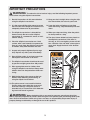
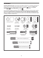
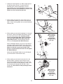
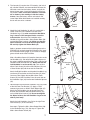
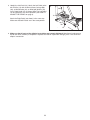
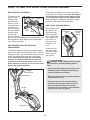
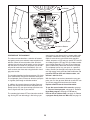
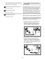
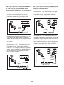
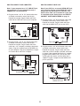
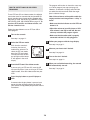
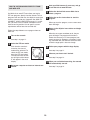
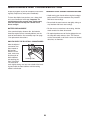
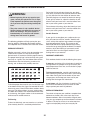
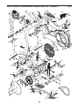
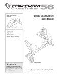
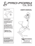
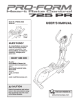
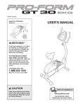
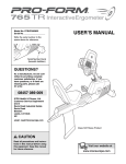
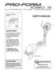
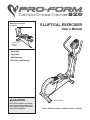
Model No. 831.283521
Serial No.
ELLIPTICAL EXERCISER
User’s Manual
Serial
Number
Decal
• Assembly
• Operation
• Maintenance
• Part List and Drawing
CAUTION
Read all precautions and instructions in this manual before using
this equipment. Keep this manual for future reference.
Patent Pending
Sears, Roebuck and Co., Hoffman Estates, IL 60179
TABLE OF CONTENTS
IMPORTANT PRECAUTIONS . . . . . . . . . . . . . . . . . . . . . . . . . . . . . . . . . . . . . . . . . . . . . . . . . . . . . . . . . . . . . . . .3
BEFORE YOU BEGIN . . . . . . . . . . . . . . . . . . . . . . . . . . . . . . . . . . . . . . . . . . . . . . . . . . . . . . . . . . . . . . . . . . . . . .4
ASSEMBLY . . . . . . . . . . . . . . . . . . . . . . . . . . . . . . . . . . . . . . . . . . . . . . . . . . . . . . . . . . . . . . . . . . . . . . . . . . . . . . .5
HOW TO USE THE ELLIPTICAL CROSSTRAINER . . . . . . . . . . . . . . . . . . . . . . . . . . . . . . . . . . . . . . . . . . . . . . .9
MAINTENANCE AND TROUBLESHOOTING . . . . . . . . . . . . . . . . . . . . . . . . . . . . . . . . . . . . . . . . . . . . . . . . . . .20
CONDITIONING GUIDELINES . . . . . . . . . . . . . . . . . . . . . . . . . . . . . . . . . . . . . . . . . . . . . . . . . . . . . . . . . . . . . . .21
PART LIST . . . . . . . . . . . . . . . . . . . . . . . . . . . . . . . . . . . . . . . . . . . . . . . . . . . . . . . . . . . . . . . . . . . . . . . . . . . . . .22
EXPLODED DRAWING . . . . . . . . . . . . . . . . . . . . . . . . . . . . . . . . . . . . . . . . . . . . . . . . . . . . . . . . . . . . . . . . . . . .23
HOW TO ORDER REPLACEMENT PARTS . . . . . . . . . . . . . . . . . . . . . . . . . . . . . . . . . . . . . . . . . . . . .Back Cover
FULL 90 DAY WARRANTY . . . . . . . . . . . . . . . . . . . . . . . . . . . . . . . . . . . . . . . . . . . . . . . . . . . . . . . . . .Back Cover
2
IMPORTANT PRECAUTIONS
WARNING:
To reduce the risk of serious injury, read the following important precautions before using the elliptical crosstrainer.
1. Read all instructions in this manual before
using the elliptical crosstrainer.
11. Keep your back straight when using the elliptical crosstrainer; do not arch your back.
2. It is the responsibility of the owner to ensure
that all users of the elliptical crosstrainer are
adequately informed of all precautions.
12. If you feel pain or dizziness at any time
while exercising, stop immediately and cool
down.
3. The elliptical crosstrainer is intended for
home use only. Do not use the elliptical
crosstrainer in a commercial, rental, or institutional setting.
13. When you stop exercising, allow the pedals
to slowly come to a stop.
14. The decal shown below has been placed on
the elliptical crosstrainer. If the decal is
missing, or if it is not legible, please call tollfree 1-888-533-1333 and order a free replacement decal. Apply the decal in the location
shown.
4. Place the elliptical crosstrainer on a level
surface, with a mat beneath it to protect the
floor or carpet. Keep the elliptical crosstrainer indoors, away from moisture and dust.
5. Inspect and properly tighten all parts regularly. Replace any worn parts immediately.
6. Keep children under 12 and pets away from
the elliptical crosstrainer at all times.
7. The elliptical crosstrainer should not be used
by persons weighing more than 250 pounds.
8. Wear appropriate exercise clothes when
using the elliptical crosstrainer. Always wear
athletic shoes for foot protection while exercising.
9. Hold the handgrip pulse sensor or the handlebars when mounting, dismounting, or
using the elliptical crosstrainer.
10. The pulse sensor is not a medical device.
Various factors may affect the accuracy of
heart rate readings. The pulse sensor is
intended only as an exercise aid in determining heart rate trends in general.
WARNING:
Before beginning this or any exercise program, consult your physician.
This is especially important for persons over the age of 35 or persons with pre-existing health problems. Read all instructions before using. Sears assumes no responsibility for personal injury or
property damage sustained by or through the use of this product.
3
BEFORE YOU BEGIN
Congratulations for selecting the new PROFORM®
820 CARDIO CROSSTRAINER. The PROFORM® 820
is an incredibly smooth exerciser that moves your feet
in a natural elliptical path, minimizing the impact on
your knees and ankles. And the unique PROFORM®
820 features adjustable resistance and a state-of-theart console to help you get the most from your
exercise.
questions after reading this manual, call 1-800-4-MYHOME® (1-800-469-4663). To help us assist you,
please note the product model number and serial
number before calling. The model number is
831.283521. The serial number can be found on a
decal attached to the elliptical crosstrainer (see the
front cover of this manual for the location of the decal).
Before reading further, please familiarize yourself with
the parts that are labeled in the drawing below.
For your benefit, read this manual carefully before
you use the elliptical crosstrainer. If you have
Handgrip
Pulse Sensor
Console
Handlebar
Water Bottle Holder*
FRONT
Pedal
Flex Bar
Wheel
Leveling Foot
Pedal Disk
LEFT SIDE
BACK
*No water bottle is included
4
ASSEMBLY
Assembly requires two persons. Place all parts of the elliptical crosstrainer in a cleared area and remove the
packing materials. Do not dispose of the packing materials until assembly is completed. In addition to the
, an adjustable
included allen wrenches, assembly requires a phillips screwdriver
wrench
, and a rubber mallet
.
As you assemble the elliptical crosstrainer, use the drawings below to identify the small parts used in assembly.
The number in parenthesis below each drawing refers to the key number of the part, from the PART LIST on
page 22. The second number refers to the quantity needed for assembly. Note: Some small parts may have
been pre-assembled. If a part is not in the parts bag, check to see if it has been pre-assembled. If a part
is missing, call toll-free 1-888-533-1333.
Frame Spacer (83)–1
M10 Split
Washer (70)–3
M4 x 16mm
Screw (66)–4
M4 x 22mm
Screw (93)–2
M8 x 45mm Button Bolt (50)–4
Wave Washer
(95)–2
M8.5
Washer (53)–2
M8 Nylon
Locknut (46)–4
M8 x 25mm Patch
Screw (22)–2
M10 x 112mm Carriage Bolt (34)–4
M10 x 88mm Button Screw (63)–1
M10 x 78mm Button Bolt (27)–2
5
M10
Washer (38)–6
M10 Nylon
Locknut (29)–6
M10 x 35mm Carriage
Bolt (20)–2
1. Identify the Front Stabilizer (3). While another person
lifts the front of the Frame (1), attach the Front
Stabilizer to the Frame with two M10 x 112mm
Carriage Bolts (34) and two M10 Nylon Locknuts (29).
Make sure that the Front Stabilizer is turned so the
Wheels (32) are not touching the floor.
1
32
34
32
3
1
29
2. While another person lifts the back of the Frame (1),
attach the Rear Stabilizer (4) to the Frame with two
M10 x 112mm Carriage Bolts (34) and two M10 Nylon
Locknuts (29).
2
29
4
29
1
3. While another person holds the Upright (2) in the position shown, connect the Upper Wire Harness (86) to
the Lower Wire Harness (87). Carefully pull the
upper end of the Upper Wire Harness to remove
any slack. While holding the upper end of the
Upper Wire Harness, insert the Upright into the
Frame (1). Do not pinch the Wire Harnesses.
34
3
Make sure the
wire harnesses
do not get
pinched and
damaged during
this step.
91
2
Slide an M10 Split Washer (70) and a Frame Spacer
(83) onto an M10 x 88mm Button Screw (63). Insert
the Button Bolt into the Frame (1) and the Upright (2).
Make sure that the concave end of the Frame
Spacer is turned toward the Frame. Do not tighten
the Button Bolt yet.
93
63
Attach the Water Bottle Holder (91) to the Upright
(2) with two M4 x 22mm Screws (93).
86
70
87
1
83
4. While another person holds the Console (5) in the
position shown, connect the wire harness on the
Console to the Upper Wire Harness (86). Insert the
excess wire harness into the Upright (2). Next, attach
the Console to the Upright with four M4 x 16mm
Screws (66). Be careful to avoid pinching the wire
harnesses.
4
86
66
2
66
6
5
Wire
Harness
Make sure the
wire harnesses
do not get
pinched and
damaged during
this step.
5. The Console (5) requires four “D” batteries (not included); alkaline batteries are recommended. Remove the
indicated screw from the battery drawer, and pull the
battery drawer open. Insert four batteries into the battery drawer; make sure that the batteries are oriented as shown by the markings inside the battery
drawer. Close the battery drawer and reattach the
screw. Note: When the batteries are installed correctly,
the fan will turn on for a moment.
5
5
Battery
Drawer
Screw
6. Identify the Left Handlebar (9), which is marked with a
sticker. Insert the Left Handlebar into one of the
Handlebar Legs (79); make sure that the Handlebar
Leg is turned so the hexagonal holes are on the
indicated side. Attach the Left Handlebar to the
Handlebar Leg with two M8 x 45mm Button Bolts (50)
and two M8 Nylon Locknuts (46). Make sure that the
Nylon Locknuts are inside of the hexagonal holes.
Do not fully tighten the Button Bolts yet.
Batteries
6
Grease
9
Apply a generous amount of the included grease to the
Pivot Axle (97) and to the two M8.5 Washers (53). Insert
the Pivot Axle into the Upright (2) and centre it. Reapply
grease to both ends of the Pivot Axle.
Tube
97
25
53
22
Slide a Handlebar Spacer (25) onto the short tube on the
Left Handlebar (9), and rotate the Handlebar Spacer so
the arrow is pointing toward the floor. Then, slide the Left
Handlebar onto the Pivot Axle (97). Make sure that the
Left Handlebar is on the correct side. Turn an M8 x
25mm Patch Screw (22) with an M8.5 Washer (53) and
a Wave Washer (95) into the end of the Pivot Axle.
2
Arrow
95
46
23
50
Hexagonal
Holes
79
Attach the Right Handlebar and the other Handlebar Leg
(not shown) to each other and the Pivot Axle (97) in the
same way. Next, tighten the two M8 x 25mm Patch
Screws (22) into the Pivot Axle. Press the small tabs on
the Handlebar Caps (23) into the two Handlebar Spacers
(25).
7. Hold the lower end of the left Handlebar Leg (79) inside
of the left Front Flex Bracket (17). Apply a small
amount of grease to an M10 x 78mm Button Bolt (27).
Attach the left Handlebar Leg to the left Front Flex
Bracket with the Button Bolt, two M10 Washers (38),
and an M10 Nylon Locknut (29). Do not overtighten
the Nylon Locknut; the left Handlebar Leg must be
able to pivot freely.
7
79
79
29
38
38
27
Attach the right Handlebar Leg (79) to the right Front
Flex Bracket (17) in the same way.
See step 6. Tighten the M8 x 45mm Button Bolts (50)
in the Handlebar Legs (79). See step 3. Tighten the
M10 x 88mm Button Screw (63).
7
17
Grease
17
8. Identify the Left Pedal (13). Attach the Left Pedal to the
left Flex Bar (14) with an M10 x 35mm Carriage Bolt
(20), an M10 Washer (38), an M10 Split Washer (70),
and a Pedal Knob (15) as shown. Note: The Left Pedal
can be attached in any of five positions (see HOW TO
ADJUST THE PEDALS on page 9).
8
20
13
Attach the Right Pedal (not shown) in the same way.
Make sure that both Pedals are in the same position.
14 38
70
15
9. Make sure that all parts of the elliptical crosstrainer are properly tightened. Note: Some hardware may
be left over after assembly is completed. To protect the floor or carpet from damage, place a mat under the
elliptical crosstrainer.
8
HOW TO USE THE ELLIPTICAL CROSSTRAINER
HOW TO ADJUST THE PEDALS
To dismount the elliptical crosstrainer, wait until the
pedals come to a complete stop. Note: The elliptical
crosstrainer does not have a free wheel; the pedals will continue to move until the flywheel stops.
When the pedals are stationary, step off the highest
pedal first. Then, step off the lowest pedal.
The motion of the
pedals is deterBolt Flex Bar
mined by their
positions on the
flex bars. There
are five positions.
To adjust each
pedal, first loosen
Pedal
the knob beneath
Knob
the pedal. Next,
push the bolt
upward, slide the
pedal forward or backward to the desired position, and
then retighten the knob. Make sure that both pedals
are in the same position.
HOW TO USE THE HANDLEBARS
The handlebars are
designed to add
upper-body exercise to your workouts. Push and pull
the handlebars as
you exercise to
work your arms,
shoulders, and
back.
HOW TO EXERCISE ON THE ELLIPTICAL
CROSSTRAINER
Handlebars
Handgrip
Pulse
Sensor
To exercise only
your lower body,
hold the handgrip
pulse sensor as
you exercise.
To mount the elliptical crosstrainer, hold the handgrip
pulse sensor and step onto the pedal that is in the lowest position. Then, step onto the other pedal. Push the
pedals until they begin to move with a continuous
motion. Note: The pedal disks can turn in either
direction. It is recommended that you move the
pedal disks in the direction shown by the arrow
below; however, for variety, you can turn the pedal
disks in the opposite direction.
CAUTION:
Before using the elliptical crosstrainer, read the following precautions.
• Always hold the handgrip pulse sensor or the
handlebars when mounting, dismounting, or
using the elliptical crosstrainer.
Handgrip
Pulse Sensor
Handlebars
• When you stop exercising, allow the pedals to
slowly come to a stop.
• The pulse sensor is not a medical device.
Various factors may affect the accuracy of
heart rate readings. The pulse sensor is
intended only as an exercise aid in determining heart rate trends in general.
Pedals
Pedal Disk
9
Fan Button
Display Buttons
On/Reset Button
Resistance Buttons
FEATURES OF THE CONSOLE
The advanced console offers a selection of features
designed to make your workouts more enjoyable and
effective. When the manual mode of the console is
selected, the resistance of the pedals can be changed
with the touch of a button. As you pedal, the console
will provide continuous exercise feedback. You can
even measure your heart rate using the built-in handgrip pulse sensor.
The console also offers four Smart programs. Each program automatically changes the resistance of the pedals and prompts you to increase or decrease your pace
as it guides you through an effective workout.
In addition, the console features two Heart Rate programs that change the resistance of the pedals and
prompt you to vary your pace to keep your heart rate
near a target heart rate as you exercise.
The console also features iFIT.com interactive technology. Having iFIT.com technology is like having a per-
sonal trainer in your home. Using a stereo audio cable
(available at electronics stores), you can connect the
elliptical crosstrainer to your home stereo, portable
stereo, computer, or VCR and play special iFIT.com CD
and video programs (iFIT.com CDs and videocassettes
are available separately). iFIT.com CD and video programs automatically control the resistance of the pedals and prompt you to vary your pace as a personal
trainer coaches you through every step of your workout. High-energy music provides added motivation. To
purchase iFIT.com CDs and videocassettes, call
toll-free 1-888-533-1333.
With the elliptical crosstrainer connected to your computer, you can also go to our Web site at www.iFIT.com
and access programs directly from the internet.
Explore www.iFIT.com for more information.
To use the manual mode of the console, see page
11. To use a Smart program, see page 13. To use a
Heart Rate program, see page 14. To use an
iFIT.com CD or videocassette, see page 18. To use
a program directly from our Web site, see page 19.
10
seconds. If you use the handgrip pulse sensor,
the display will also show your heart rate (see
step 5 on page 12).
HOW TO USE THE MANUAL MODE
1
Turn on the console.
To view only the distance
Upper Button
you have pedaled or the
number of calories or fat
calories you have burned,
press the upper button on
the left side of the large
display until only the word
DISTANCE, CALORIES, or
FAT CALORIES appears in the upper section of
the large display. Make sure that the word SCAN
does not appear. To again view the distance you
have pedaled and the numbers of calories and
fat calories you have burned, press the upper
button until the word SCAN reappears.
Note: The console requires four 1.5V “D” batteries
(see assembly step 5 on page 7).
To turn on the console, press the On/Reset button
or begin pedaling. (See the drawing on page 11 to
identify the On/Reset button.)
2
Select the manual mode.
Each time the console is
turned on, the manual
mode will be selected. If a
program has been selected, select the manual
mode by pressing the
Program button repeatedly until the letters RPM
appear in the small display.
3
The center of
the large display
will show the
elapsed time and
your current pace
(pace is shown in
minutes per mile). The display will change from
one number to the other every few seconds.
Note: When a program is selected (except for the
SelfSelect program), the display will show the
time remaining in the program instead of the
elapsed time.
Begin pedaling and change the resistance of
the pedals as desired.
As you pedal, change the resistance of the pedals by pressing the + and – buttons below the
large display. There are ten resistance levels—
level 10 is the most challenging. Note: After the
buttons are pressed, it will take a few seconds for
the resistance to reach the selected setting.
4
To view only the elapsed time or your pace, press
the center button on the left side of the large display until only the word TIME or PACE appears.
Make sure that the word SCAN does not appear.
To view both the elapsed time and your pace,
press the center button until the word SCAN
reappears.
Follow your progress with small display and
the large display.
The small display will
show your pedaling pace,
in revolutions per minute
(RPM). The indicator bar
in the small display will
increase or decrease in
length as you increase or
decrease your pedaling
pace.
The lower section of the large
display will show
your pedaling
speed and the
resistance level.
The display will change from one number to the
other every few seconds.
Indicator Bar
The upper section of the
large display
will show the
distance you
have pedaled
and the numbers of calories and fat calories you
have burned (see FAT BURNING on page 21 for
an explanation of fat calories). The display will
change from one number to the next every few
To view only your pedaling speed or the resistance level, press the lower button on the left
side of the large display until only the word
SPEED or RESISTANCE appears. Make sure
that the word SCAN does not appear. To view
both your pedaling speed and the resistance
level, press the lower button until the word SCAN
reappears.
11
For the most accurate heart rate reading, continue
to hold the handgrips for about 30 seconds. Note:
When you first hold the handgrips, the large display will show your heart rate continuously for 30
seconds. The display will then show your heart
rate along with other feedback modes.
To reset the displays, press the On/Reset button.
Note: The console can show
speed and distance in either
miles or kilometers. The letters MPH or KM/H will appear in the lower section
of the large display to show which system of measurement is selected. To change the system of
measurement, hold down the On/Reset button for
about six seconds. Note: When the button is held
down, the fan will turn on for a moment. When the
batteries are replaced, it may be necessary to reselect the desired system of measurement.
5
6
Turn on the fan if desired.
To turn on the
fan at low speed,
press the fan
button. To turn
Thumb
on the fan at
Wheel
high speed,
Fan
press the fan
Button
button a second
time. To turn off
the fan, press the fan button a third time. Note: If
the fan is turned on but the pedals are not moved
for thirty seconds, the fan will automatically turn
off to conserve the batteries.
Measure your heart rate if desired.
If there are
thin sheets of
plastic on the
metal contacts
on the handMetal
grips, peel off
Contacts
the plastic. To
use the handgrip pulse sensor, hold the handgrips with your palms resting
against the metal contacts. Avoid moving your
hands. When your pulse is detected, the heartshaped indicator in the large display will flash
each time your heart beats. After a moment, two
dashes (– –) will appear and then your heart rate
will be shown.
Rotate the thumb wheel on the right side of the
console to pivot the fan to the desired angle.
7
When you are finished exercising, the console
will automatically turn off.
If the pedals are not moved for a few seconds,
the displays will pause and the time will flash in
the large display.
If the pedals are not moved and the console buttons are not pressed for a few minutes, the console will turn off to conserve the batteries.
12
The target pace
for the current
Indicator
period will be
Bar
shown by the
arrows in the
Arrows
small display. To
pedal at the target
pace, simply
increase or decrease your pace until there is one
arrow pointing to each segment of the indicator
bar (see the drawing above). At the end of each
period, the number of arrows will change if a different target pace is programmed for the next
period. When the number of arrows changes,
change your pace until there is one arrow pointing to each segment of the indicator bar.
Important: The target pace is intended only to
provide a goal. Your actual pace may be slower than the target pace, especially during the
first few months of your exercise program.
Make sure to pedal at a pace that is comfortable for you.
HOW TO USE A SMART PROGRAM
Each Smart program will automatically change the
resistance of the pedals and prompt you to increase or
decrease your pace as it guides you through an effective workout. Programs 3 and 4 are weight loss programs, program 5 is an aerobic program, and program
6 is a high-performance interval-training program.
Follow the steps below to use a Smart program.
1
Turn on the console.
See step 1 on page 11.
2
Select one of the Smart programs.
Each time the console is
turned on, the manual
mode will be selected. To
select a Smart program,
press the Program button
repeatedly until the number 3, 4, 5, or 6 appears in
the small display.
3
During the program, the center of the large display will show the time remaining in the program.
If you stop pedaling for a few seconds, the displays will pause and the time will flash. If you
continue pedaling after the program is completed,
the displays will continue to show exercise feedback.
Begin pedaling to start the program.
To start the program, simply begin pedaling. Each
Smart program consists of 20 or 30 one-minute
periods. One resistance level and one target pace
are programmed for each period. (The same
resistance level and/or target pace may be programmed for two or more consecutive periods.)
At the end of each period of the program, the
resistance of the pedals will automatically change
if a different resistance level is programmed for
the next period. Note: If the resistance level is too
high or too low, you can change it by pressing the
+ and – buttons below the large display. However,
when the current period is completed, the resistance of the pedals will automatically change if a
different resistance level is programmed for the
next period.
13
4
Follow your progress with the large display.
See step 4 on page 11.
5
Measure your heart rate if desired.
See step 5 on page 12.
6
Turn on the fan if desired.
See step 6 on page 12.
7
When you are finished exercising, the console
will automatically turn off.
See step 7 on page 12.
to operate properly. Each time you hold the
handgrips, keep your hands on the metal contacts for at least 30 seconds. Note: When you
are not holding the handgrips, the letters PLS will
appear in the large display instead of your heart
rate.
HOW TO USE A HEART RATE PROGRAM
Heart Rate program 1 is designed to keep your heart
rate between 65% and 85% of your maximum heart
rate during your workout. (Your maximum heart rate is
estimated by subtracting your age from 220. For
example, if you are 25 years old, your maximum heart
rate is 195 beats per minute.) Heart Rate program 2 is
designed to keep your heart rate near a target heart
rate that you select.
5
To start the program, simply begin pedaling.
Program 1 consists of 20 one-minute periods.
One resistance level and one target heart rate are
programmed for each period. (The same resistance level and/or target heart rate may be programmed for two or more consecutive periods.)
Program 2 is sixty minutes long (you may choose
to use only part of the program). The same resistance level and target heart rate are programmed
for the entire program.
Follow the steps below to use a Heart Rate program.
1
Turn on the console.
See step 1 on page 11.
2
Select one of the Heart Rate programs.
If program 1 is selected, the resistance of the
pedals will periodically change. (Note: If the resistance level is too high or too low, you can change
it by pressing the + and – buttons below the large
display. However, when the current period is completed, the resistance of the pedals may automatically change.) If program 2 is selected, the
resistance of the pedals will not change. Note:
You can change the resistance level for the entire
program by pressing the + and – buttons below
the large display if desired.
Each time the console is
turned on, the manual
mode will be selected. To
select a Heart Rate program, press the Program
button repeatedly until the
number 1 or 2 appears in
the small display.
3
Enter your age or a target heart rate.
If program 1 is selected, the word AGE will
appear in the large display and the current age
setting will flash. If you have already entered your
age, press the Enter button. If you have not
entered your age, press the small + and – buttons
to enter your age. Then, press the Enter button.
Once you have entered your age, it will be saved
in memory until the batteries are replaced.
If program 2 is selected, the letters PLS (pulse)
will appear in the large display and the current
target heart rate will flash. If you do not wish to
change the target heart rate, press the Enter button. If you wish to change the target heart rate,
press the small + and – buttons. Then, press the
Enter button. The target heart rate can be from 70
to 170 beats per minute.
4
Begin pedaling to start the program.
Hold the handgrip pulse sensor.
It is not necessary to hold the handgrips continuously during a Heart Rate program; however, you
must hold the handgrips frequently for the program
14
During programs
1 and 2, the
Indicator
arrows in the
Bar
small display will
help you to keep
Arrows
your heart rate
near the current
target heart rate.
When you hold the handgrip pulse sensor, the
console will compare your heart rate to the current target heart rate. If your heart rate is too far
above or below the target heart rate, the number
of arrows in the small display will change to
prompt you to increase or decrease your pace.
When the number of arrows changes, change
your pace until there is one arrow pointing to
each segment of the indicator bar. Important:
The target pace is intended only to provide a
goal. Your actual pace may be slower than the
target pace, especially during the first few
months of your exercise program. Make sure
to pedal at a pace that is comfortable for you.
Note: If you stop pedaling for a few seconds, the
program will end. To use the program again, reselect it and start it at the beginning.
6
Follow your progress with the large display.
See step 4 on page 11.
7
Turn on the fan if desired.
See step 6 on page 12.
8
When you are finished exercising, the console
will automatically turn off.
HOW TO CONNECT YOUR CD PLAYER, VCR,
OR COMPUTER
To use iFIT.com CDs, the elliptical crosstrainer must be
connected to your portable CD player, portable stereo,
home stereo, or computer with CD player. See pages 15
to 17 for connecting instructions. To use iFIT.com
videocassettes, the elliptical crosstrainer must be connected to your VCR. See page 17 for connecting instructions. To use iFIT.com programs directly from our
Web site, the elliptical crosstrainer must be connected to
your computer. See page 17 for connecting instructions.
HOW TO CONNECT YOUR PORTABLE CD PLAYER
See step 7 on page 12.
Note: If your CD player has separate LINE OUT and
PHONES jacks, see instruction A below. If your CD
player has only one jack, see instruction B.
A. Plug one end of a 1/8” to 1/8” stereo audio cable
(available at electronics stores) into the jack
beneath the console. Plug the other end of the
cable into the LINE OUT jack on your CD player.
Plug your headphones into the PHONES jack.
A
PHONES LINE OUT
LINE OUT
PHONES
Headphones
Audio
Cable
B. Plug one end of a 1/8” to 1/8” stereo audio cable
(available at electronics stores) into the jack
beneath the console. Plug the other end of the
cable into a 1/8” Y-adapter (available at electronics
stores). Plug the Y-adapter into the PHONES jack
on your CD player. Plug your headphones into the
other side of the Y-adapter.
B
PHONES
PHONES
Audio
Cable
1/8”
Y-adapter
Headphones
15
HOW TO CONNECT YOUR PORTABLE STEREO
HOW TO CONNECT YOUR HOME STEREO
Note: If your stereo has an RCA-type AUDIO OUT
jack, see instruction A below. If your stereo has a
1/8” LINE OUT jack, see instruction B. If your
stereo has only a PHONES jack, see instruction C.
Note: If your stereo has an unused LINE OUT jack,
see instruction A below. If the LINE OUT jack is
being used, see instruction B.
A. Plug one end of a 1/8” to RCA stereo audio cable
(available at electronics stores) into the jack
beneath the console. Plug the other end of the
cable into the LINE OUT jack on your stereo.
A. Plug one end of a 1/8” to RCA stereo audio cable
(available at electronics stores) into the jack
beneath the console. Plug the other end of the
cable into the AUDIO OUT jack on your stereo.
A
CD
A/B
VCR
AUDIO OUT
Amp
LINE OUT
LINE OUT
RIGHT
LINE OUT
LEFT
Audio
Cable
Audio
Cable
B. Plug one end of a 1/8” to RCA stereo audio cable
(available at electronics stores) into the jack beneath
the console. Plug the other end of the cable into an
RCA Y-adapter (available at electronics stores).
Next, remove the wire that is currently plugged into
the LINE OUT jack on your stereo and plug the wire
into the unused side of the Y-adapter. Plug the Yadapter into the LINE OUT jack on your stereo.
B. See the drawing above. Plug one end of a 1/8” to
1/8” stereo audio cable (available at electronics
stores) into the jack beneath the console. Plug the
other end of the cable into the LINE OUT jack on
your stereo.
C. Plug one end of a 1/8” to 1/8” stereo audio cable
(available at electronics stores) into the jack
beneath the console. Plug the other end of the
cable into a 1/8” Y-adapter (available at electronics
stores). Plug the Y-adapter into the PHONES jack
on your stereo. Plug your headphones into the
other side of the Y-adapter.
B
CD
VCR
Amp
LINE OUT
C
Audio
Cable
PHONES
Audio
Cable
1/8”
Y-adapter
RCA
Y-adapter
Wire removed from
LINE OUT jack
Headphones
16
HOW TO CONNECT YOUR COMPUTER
HOW TO CONNECT YOUR VCR
Note: If your computer has a 1/8” LINE OUT jack,
see instruction A. If your computer has only a
PHONES jack, see instruction B.
Note: If your VCR has an unused AUDIO OUT jack,
see instruction A below. If the AUDIO OUT jack is
being used, see instruction B. If you have a TV
with a built-in VCR, see instruction B. If your VCR
is connected to your home stereo, see HOW TO
CONNECT YOUR HOME STEREO on page 16.
A. Plug one end of a 1/8” to 1/8” stereo audio cable
(available at electronics stores) into the jack
beneath the console. Plug the other end of the
cable into the LINE OUT jack on your computer.
A. Plug one end of a 1/8” to RCA stereo audio cable
(available at electronics stores) into the jack
beneath the console. Plug the other end of the
cable into the AUDIO OUT jack on your VCR.
A
LINE OUT
A
ANT. IN
VIDEO AUDIO
IN
RF OUT
CH
3 4
OUT
Audio
Cable
AUDIO OUT
RIGHT
LEFT
Audio
Cable
B. Plug one end of a 1/8” to 1/8” stereo audio cable
(available at electronics stores) into the jack
beneath the console. Plug the other end of the
cable into a 1/8” Y-adapter (available at electronics
stores). Plug the Y-adapter into the PHONES jack
on your computer. Plug your headphones or speakers into the other side of the Y-adapter.
B. Plug one end of a 1/8” to RCA stereo audio cable
(available at electronics stores) into the jack
beneath the console. Plug the other end of the
cable into an RCA Y-adapter (available at electronics stores). Next, remove the wire that is currently
plugged into the AUDIO OUT jack on your VCR
and plug the wire into the unused side of the Yadapter. Plug the Y-adapter into the AUDIO OUT
jack on your VCR.
B
PHONES
B
Audio
Cable
ANT. IN
VIDEO AUDIO
IN
RF OUT
1/8”
Y-adapter
CH
3 4
OUT
RCA
Y-adapter
Headphones/Speakers
Audio Cable
Wire removed from
AUDIO OUT jack
17
The program will function in almost the same way
as a Smart program (see step 3 on page 13).
However, an electronic “chirping” sound will alert
you when the resistance level and/or the target
pace is about to change.
HOW TO USE IFIT.COM CD AND VIDEO
PROGRAMS
To use iFIT.com CDs or videocassettes, the elliptical
crosstrainer must be connected to your portable CD
player, portable stereo, home stereo, computer with
CD player, or VCR. See HOW TO CONNECT YOUR
CD PLAYER, VCR, OR COMPUTER on page 15. To
purchase iFIT.com CDs and videocassettes, call
toll-free 1-888-533-1333.
Note: If the resistance of the pedals and/or the
target pace does not change when a “chirp” is
heard:
• Make sure that the indicator near the iFIT.com
button is lit.
• Adjust the volume of your CD player or VCR.
If the volume is too high or too low, the console may not detect the program signals.
Follow the steps below to use an iFIT.com CD or
video program.
1
Turn on the console.
• Make sure that the audio cable is properly
connected and that it is fully plugged in.
See step 1 on page 11.
2
5
Select the iFIT.com mode.
See step 4 on page 11.
Each time the console is
turned on, the manual
mode will be selected. To
select the iFIT.com mode,
press the iFIT.com button.
The indicator near the button will light and the letters
IF will appear in the small
display.
3
6
Measure your heart rate if desired.
See step 5 on page 12.
7
Turn on the fan if desired.
See step 6 on page 12.
8
Insert the iFIT.com CD or videocassette.
If you are using an iFIT.com CD, insert the CD
into your CD player. If you are using an iFIT.com
videocassette, insert the videocassette into your
VCR.
4
Follow your progress with the large display.
When you are finished exercising, the console
will automatically turn off.
See step 7 on page 12.
Press the play button on your CD player or
VCR.
A moment after the play button is pressed, your
personal trainer will begin guiding you through
your workout. Simply follow your personal trainer’s
instructions.
18
HOW TO USE PROGRAMS DIRECTLY FROM
OUR WEB SITE
Our Web site at www.iFIT.com allows you to play
iFIT.com programs directly from the internet. To use
programs from our Web site, the elliptical crosstrainer
must be connected to your computer. See HOW TO
CONNECT YOUR COMPUTER on page 17. In addition, you must have an internet connection and an
internet service provider. A list of specific system
requirements will be found on our Web site.
Start your Web browser, if necessary, and go
to our Web site at www.iFIT.com.
5
Follow the desired links on our Web site to
select a program.
6
Follow the on-line instructions to start the
program.
When you start the program, an on-screen countdown will begin.
7
Follow the steps below to use a program from our
Web site.
1
4
When the on-screen countdown ends, the program will begin. The program will function in
almost the same way as a Smart program (see
step 3 on page 13). However, an electronic “chirping” sound will alert you when the resistance level
and/or the target pace is about to change.
Turn on the console.
See step 1 on page 11.
2
Select the iFIT.com mode.
Each time the console is
turned on, the manual
mode will be selected. To
select the iFIT.com mode,
press the iFIT.com button.
The indicator near the button will light and the letters
IF will appear in the small
display.
3
Return to the elliptical crosstrainer and begin
pedaling.
8
Follow your progress with the large display.
See step 4 on page 11.
9
Measure your heart rate if desired.
See step 5 on page 12.
you are finished exercising, the console
10 When
will automatically turn off.
Go to your computer and start an internet connection.
See step 7 on page 12.
19
MAINTENANCE AND TROUBLESHOOTING
HANDGRIP PULSE SENSOR TROUBLESHOOTING
Inspect and tighten all parts of the elliptical crosstrainer
regularly. Replace any worn parts immediately.
• Avoid moving your hands while using the handgrip
pulse sensor. Excessive movement may interfere
with heart rate readings.
To clean the elliptical crosstrainer, use a damp cloth
and a small amount of mild soap. Important: To
avoid damage to the console, keep liquids away
from the console and keep the console out of
direct sunlight.
• Do not hold the metal contacts too tightly; doing so
may interfere with heart rate readings.
BATTERY REPLACEMENT
• For the most accurate heart rate reading, hold the
metal contacts for about 30 seconds.
If the console displays become dim, the batteries
should be replaced; most console problems are the
result of low batteries. See assembly step 5 on page
7 for replacement instructions.
• For optimal performance of the handgrip pulse sensor, keep the metal contacts clean. The contacts
can be cleaned with a soft cloth—never use alcohol,
abrasives, or chemicals.
HOW TO LEVEL THE ELLIPTICAL CROSSTRAINER
After the elliptical
crosstrainer has
been moved to
the location
where it will be
used, make sure
that the ends of
both stabilizers
Leveling Foot
are touching the
floor. If the elliptical crosstrainer
rocks slightly during use, turn one or both of the leveling feet under the front stabilizer until the rocking
motion is eliminated.
20
CONDITIONING GUIDELINES
During the first few minutes of exercise, your body
uses easily accessible carbohydrate calories for energy. Only after the first few minutes of exercise does
your body begin to use stored fat calories for energy.
If your goal is to burn fat, adjust the intensity of your
exercise until your heart rate is near the lowest number in your training zone as you exercise.
WARNING:
• Before beginning this or any exercise program, consult your physician. This is especially important for persons over the age of
35 or persons with pre-existing health problems.
For maximum fat burning, adjust the intensity of your
exercise until your heart rate is near the middle number in your training zone as you exercise.
• The pulse sensor is not a medical device.
Various factors may affect the accuracy of
heart rate readings. The pulse sensor is
intended only as an exercise aid in determining heart rate trends in general.
Aerobic Exercise
If your goal is to strengthen your cardiovascular system, your exercise must be “aerobic.” Aerobic exercise is activity that requires large amounts of oxygen
for prolonged periods of time. This increases the
demand on the heart to pump blood to the muscles,
and on the lungs to oxygenate the blood. For aerobic
exercise, adjust the intensity of your exercise until
your heart rate is near the highest number in your
training zone as you exercise.
The following guidelines will help you to plan your
exercise program. Remember that proper nutrition
and adequate rest are essential for successful results.
EXERCISE INTENSITY
Whether your goal is to burn fat or to strengthen your
cardiovascular system, the key to achieving the
desired results is to exercise with the proper intensity.
The proper intensity level can be found by using your
heart rate as a guide. The chart below shows recommended heart rates for fat burning, maximum fat
burning, and cardiovascular (aerobic) exercise.
WORKOUT GUIDELINES
Each workout should include the following three parts:
A warm-up, consisting of 5 to 10 minutes of stretching
and light exercise. A proper warm-up increases your
body temperature, heart rate, and circulation in preparation for exercise.
Training zone exercise, consisting of 20 to 30 minutes of exercising with your heart rate in your training
zone. Note: During the first few weeks of your exercise program, do not keep your heart rate in your
training zone for longer than 20 minutes.
A cool-down, with 5 to 10 minutes of stretching. This
will increase the flexibility of your muscles and will
help to prevent post-exercise problems.
To find the proper heart rate for you, first find your age
at the bottom of the chart (ages are rounded off to the
nearest ten years). Next, find the three numbers above
your age. The three numbers are your “training zone.”
The lower two numbers are recommended heart rates
for fat burning; the highest number is the recommended heart rate for aerobic exercise.
EXERCISE FREQUENCY
To maintain or improve your condition, complete three
workouts each week, with at least one day of rest
between workouts. After a few months of regular exercise, you may complete up to five workouts each week
if desired. The key to success is to make exercise a
regular and enjoyable part of your everyday life.
Fat Burning
To burn fat effectively, you must exercise at a relatively low intensity level for a sustained period of time.
21
PART LIST—Model No. 831.283521
Key No. Qty.
1
2
3
4
5
6
7
8
9
10
11
12
13
14
15
16
17
18
19
20
21
22
23
24
25
26
27
28
29
30
31
32
33
34
35
36
37
38
39
40
41
42
43
44
45
46
47
48
49
50
1
1
1
1
1
1
1
2
1
1
2
1
1
2
2
1
2
4
12
2
4
2
2
6
2
2
2
4
6
1
1
2
2
4
2
1
1
6
1
2
1
2
1
1
4
7
2
1
1
4
Description
R0804A
Key No. Qty.
Frame
Upright
Front Stabilizer
Rear Stabilizer
Console
Left Side Shield
Right Side Shield
Pedal Disc
Left Handlebar
Right Handlebar
Foam Grip
Right Pedal
Left Pedal
Flex Bar
Pedal Knob
Left Flex Bracket
Front Flex Bracket
Rear Flex Bushing
M6 x 33mm Flat Bolt
M10 x 35mm Carriage Bolt
Snap Ring
M8 x 25mm Patch Screw
Handlebar Cap
Handlebar Bushing
Handlebar Spacer
Upright Spacer
M10 x 78mm Button Bolt
Front Flex Bushing
M10 Nylon Locknut
Upright Bushing
Left Front Endcap
Wheel
M6 x 72mm Button Screw
M10 x 112mm Carriage Bolt
Rear Stabilizer Endcap
Left Crank Arm
Pulley
M10 Washer
Crank
Crank Bearing
Flywheel
Flywheel Bearing
Magnet
Flywheel Axle
M8.5mm Washer
M8 Nylon Locknut
Crank Screw
Right Crank Arm
M6 x 25mm Bolt
M8 x 45mm Button Bolt
51
52
53
54
55
56
57
58
59
60
61
62
63
64
65
66
67
68
69
70
71
72
73
74
75
76
77
78
79
80
81
82
83
84
85
86
87
88
89
90
91
92
93
94
95
96
97
#
#
#
4
1
2
1
1
1
2
12
16
4
4
4
1
2
8
6
4
1
1
3
2
2
1
8
2
1
1
1
2
1
1
1
1
4
1
1
1
2
2
4
1
4
2
1
2
2
1
2
1
1
Description
M6 x 18mm Bolt
“C” Magnet Bracket
M8.5 Washer
“C” Magnet
Motor
Belt
M8 x 33mm Button Bolt
M6 Washer
M6 Nylon Locknut
M6 Nut
M5 Nylon Locknut
M5 x 12mm Bolt
M10 x 88mm Button Screw
M4 x 6mm Self-tapping Screw
M5 x 33mm Screw
M4 x 16mm Screw
M4 x 25mm Screw
Right Front Endcap
Reed Switch Clamp
M10 Split Washer
Handlebar Endcap
Leveling Foot
M5 x 16mm Screw
M4 x 19mm Screw
M6 Eyebolt
Spring
Reed Switch
Reed Switch Bracket
Handlebar Leg
Side Shield Cover
“U” Bracket
Right Flex Bracket
Frame Spacer
M4 x 12mm Tap Screw
Resistance Cable
Upper Wire Harness
Lower Wire Harness
Flex Bracket Spacer
M8 x 22mm Button Bolt
Motor Washer
Water Bottle Holder
M8 Nut
M4 x 22mm Screw
M6 Large Washer
Wave Washer
M3 x 12mm Screw
Pivot Axle
Allen Wrench
Grease
User’s Manual
Note: “#” indicates a non-illustrated part. Specifications are subject to change without notice. See the back cover
of this manual for information about ordering replacement parts. If a part is missing, call toll-free 1-888-5331333.
22
EXPLODED DRAWING—Model No. 831.283521
71
20
19
71
11
80
5
12
17
26
93
66
11
84
58
91
84
59 38
10 70
15
23
96
66
R0804A
19
14
18
97
24
9
22
23
26
96
95
53
53 22
46 24 95
50
24
25
24
24
25
74
82
58
59
51
74
51
74
74
2
46
67
18
6
46
24
7
88
21
59
79
50
74
38 27
87
79
86
38
30
70
38
83
38
62
68
67
8
90
55
64
3
85
28
61 61
72
31
59
60
8
46
45
75
45 66
46
42
57 54
45
89
43
41
36
47
92
92
21
40
21
66
69
40
48
39
35
29
77 78 1
73
89
76
57
60
20
45
47
46
51
29
32
42
81 44
94
75
51
52
29
32
33
72
13
4
49
29
35
34
37
19
56
17
58
65
74
60
34
27
65
90
64
29
74
28
29
63
65
28
19
59 38
70
18
16
14
15
23
88
18
21
59
59
58
FULL 90 DAY WARRANTY
For 90 days from the date of purchase, if failure occurs due to defect in material or workmanship in this
Sears Elliptical Exerciser, contact the nearest Sears Service Center throughout the United States and
Sears will repair or replace the Elliptical Exerciser, free of charge.
This warranty does not apply when the Elliptical Exerciser is used commercially or for rental purposes.
This warranty gives you specific legal rights, and you may also have other rights which vary from state
to state.
Sears, Roebuck and Co., Dept. 817WA, Hoffman Estates, IL 60179
Part No. 213495 R0804A
Printed in China © 2004 Sears, Roebuck and Co.