1
Owner's
Manual
Model No.
139.53974SRT
ICRRFTSNRN1
For Residential Use
Only
GARAGE DOOR OPENER
1/2 HP
Caution:
Read and follow all
safety rules and
operating instructions
before first use of this
product.
• Safety Precautions
• Assembly
• Installation
• Adjustment
• Care and Maintenance
• Operation
Fasten the manual
near the garage door
after installation,
• Troubleshooting LIBRARY:
• Parts List
Sears, Roebuck
and Co., Hoffman
Estates,
IL 60179
Mist (Mr Craftsman website: www.sears.com/craftsman
U.S.A.
---
MODEL
! ENTRY
INSTRUCTIONS
O
_ATEtZ-ZI-qq'
JEW
CYCLE
• SUPERCEDE
)_..._ON
CHANGE_DELETE,
Oq
IODELNUMBER
14X._.__.
PmCEusr
I_
I
•
13__.
J397_
THIS FORM ACCOMPANIES A PARTS BREAKDOWN FOR A NEW MODEL INTO THE SYSTEM.
ALSO ATTACH AN OWNERS MANUAL TO BE PUT INTO THE M/bXSERV LIBRARY.
C
PI
G
L
A
G
Y
F
:O
N
PART NIJMBER
ri_,.iON
t
I iBr)An,v-
Copi_
i-,
II
I
Entered
US-_.-.
I'll
I
II
I
I
I
I
I
Received_
"
:OMMENTS:
/
tk'I-i'ACHMENTS:
(y_
_._,,.2
0 - _(P-O-J _'/i_
_///_/
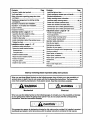
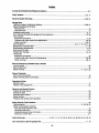
Contents
Page
A review of safetyalert symbols.................................2
You'llneed tools..........................................................3
Safety informationregardinggarage doorlocks
and ropes..................................................................3
Testing yourgarage door for sticking,binding
and balance...............................................................3
Illustrationof sectionaldoor installation.....................4
Illustrationof one-piecedoor installation
...................5
Carton inventory..........................................................6
Hardware inventory.....................................................7
Assembly section - pages 8 - 11
Assemblethe rail& installthe trolley........................8
Fasten the railto the opener.....................................9
Install the idler pulley................................................9
Installchain/sable& attach the sprocketcover......10
Tightenthe chain....................................................11
Installation section - pages 11 - 27
Installationsafety instructions
.................................11
Determine headerbracket location
Sectional door.......................................................12
One-piece door .....................................................13
Installthe header bracket.......................................14
Attach the railto headerbracket ............................15
Positionthe opener.................................................16
Hang the opener .....................................................17
Installthe door control............................................18
Contents
Page
Installthe lightand lens.................................................19
Attach emergencyreleaseropeand handle .................19
Electricalrequirememts.................................................20
Safety reversingsensorinformation
............................. 21
InstaUthe safety reversingsensor...........................22, 23
Fasten door bracket(sectionaldoor) ............................24
Fasten door bracket(one-piecedoor)...........................25
Connect doorarm to trolley(sectionaldoor).................26
Connect doorarm to trolley(one-piecedoor) ...............27
Adjustment section - pages 28 - 30
Travel limitadjustments .................................................28
Force adjustments....:....................................................29
Test the safety reversingsensor...................................30
Test the safety reversesystem ....................................30
Operationsafety instructions
...........................................31
Care of youropener.........................................................31
Maintenanceschedute....................................................31
Operationofyouropener ................................................32
Receiver and remotecontrolprogramming....................33
Having a problem?....................................................34, 35
Repair parts,railassembly..............................................36
Repair parts,installation
..................................................36
Repair parts,opener assembly .......................................37
Accassories ......................................................................38
Index ................................................................................39
How to order repairparts.................................................40
Warranty ..........................................................................40
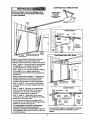
Start by reviewing these important safety alert symbols
When you see these Safety Symbols on the following pages, they will alert you to the possibility of
serious injury or death if you do not comply with the corresponding instructions. The hazard may
come from something mechanical or from electric shock. Read the instructions carefully.
[
Mechanical
WARNING
Electrical
When you see this Safety Symbol on the following pages, It will alert you to the possibility of damage
to your garage door and/or the garage door opener if you do not comply with the corresponding
instructions. Read the instructions carefully.
CAUTION
This garage door opener ls designed and tested to offer safe service provided It Is Installed, operated,
maintained and tested in strict accordance with the safety instructions contained in this manual.
J
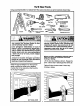
You'll Need Tools
During assembly,installationand adjustment of the opener, instructionswill call for hand toolsshown below.
Stepladder
Adjustal_e End Wrench
An unbalanced garage door might not reverse
when required and someone under the door
could be seriously injured or killed.
If your garage door binds, sticks or is out of
balance, call for professional garage door
service. Garage doors, door springs, cables,
pulleys, brackets and their hardware are under
extreme tension and can cause serious injury
or death. Do not try to loosen, move or adjust
them yourself!
Ropes left on a garage door could cause
someone to become entangled and killed.
Remove all ropes connected to the door before
installing and operating the opener.
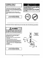
To avoid damage to the garage door and
opener, disable locks before installing and
operating the opener, Use a wood screw or nail
to hold locks in the "open" (unlocked) position.
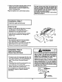
Operation at other than 120V 60 Hz will cause
opener malfunction and damage.
Before you begin, complete the following test to
make sure your door Is balanced, and is not
sticking or binding:
• Lift the door about halfway as shown. Release the
door. It shouldstay in place, supported entirely by
its springs.
Identify the type and height of your door and any
special conditionsthat exist and any additional
materials that may be required by referring to the
lists on page 4 or page 5.
• Raise and lowerthe door to see if there is any
binding or sticking.
3
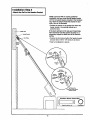
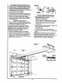
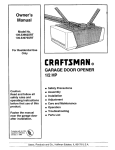
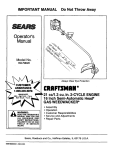
Beforeyou begin,surveyyour garageareato
seewhetheranyof the conditionsbelowapply
toyourInstallation.
Horizontal and vertical rein_,T.ement
is needed _€ lightweight garage doors
(fiberglass, stee_,aluminum, door
with glass panels, etc.).
See page 24 for deta_s.
Header Wall
Extensk>n
OR
Spring
Torsion
S_ng
Access Door
_el
t
0
Safety I
ReversingI
Sensor I
Safety Reversing Sensor
Floor must be level
across wld_ of door,
Header
Bracket
Trofley
Stop Bolt
Based on your particular requirements,there are
several installationsteps which might call for
materials and/or hardware not included in the carton,
Closed Position
Tn
• Step 1, page 12 - Look at the wall or ceiling above
the garage door. The header bracket rnustbe
securely fastened to structuralsupports.
I
Chain
• Step 5, page 17 - Do you have a finished ceiling in
your garage? If so, a supportbracket and
additionalfastening hardware may be required.
r
Release
Rope & Han_e
• Safety reversing sensor, page 21 - Depending
upon garage construction,extension brackets (see
Accessories page 38) or wood blocks may be
needed to fasten sensorsto mounting locations.
Header
Wall
• Step 10, page 22 - Floor mounting of the safety
reversing sensor will require hardware not
provided.
Door
Bracket
Door
Arm
• The opener can be installedwithin4 feet to the left
or rightof the door center if there is a torsion spring
or center bearing plate in the way of the header
bracket or door bracket area. ff your door has
extension springs, the opener mustbe installed in
the center of the door.See pages 12 and 24.
• Step 11, page 24 - Do you have a steel, aluminum,
fiberglass or glass panel door? If so, horizontal
and vertical reinforcementis required.
• Look at the garage door where it meets the floor.
It must close on the floor all the way across.
Otherwise, the safety reverse system may not
work properly. See page 30. Floor or door should
be repaired.
• Do you have an access door in additionto the
garage door?,if not, Model 53702 Emergency Key
Release is required.See page 38.
• If your door is more than 7 feet high, see the rail
extension kits listedon page 38.
You may find it helpful to refer back to this page as you proceed with the installation of your opener.
4
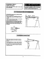
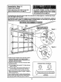
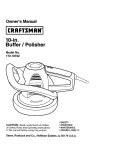
One-Piece
Before you begin, survey your garage area to
see whether any of the conditions below apply
to your installation.
Door without Track
FNSHED
OEUNO /
super bracket
. &fastening
nardwm is required.
See dege 17.
-_'_,_-_.
"_
_,
_,
Header
w,l
Zll//
Db':,
Ii II l
!11
IIIPl I I
! 7;";i
I Fi
; ,; ,:
-_
Wall
ap between floor and bottom
Safely
Ofdoor must not exceed 114".
Reversing Sensor
Door Bracket
_ii
-_
Slight
{,.
Door
\7
Garage
Curved
Emergency
_%.,.
Rope l Handle
Door
Sensor
Based on your particularrequirements,there are
several installatien steps which mightcall for
materials and/or hardware not includedin the carton.
• Step 1, page 13 - Look at the wall er ceiling above
the garage door.The header bracket rnustbe
securely fastened to structuralsupports.
• Step 5, page 17 - Do you have a finished ceiling in
your garage? If so, a support bracket and
additional fastening hardware (not provided) may
be required.
• Safety reversing sensor, page 21 - Depending on
garage construction,wood blocks or extension
brackets (see Accessories page 38) may be
needed to fasten sensors to mounting locations.
• Step 10, page 22 - Floor mountingof the safety
reversingsensor will require hardware that is not
provided.
• Step 11, page 25 - Generally, a one-piece door
does not require reinforcement.If your door is
lightweight,you can refer to the information
relating to sectional doors on page 24.
• Step 11, page 25 - Depending on your deor's
construction,you might need additional mounting
hardware for the door bracket.
• Do you have an access door in addition to the
garage door?.If not, Model 53702 Emergency Key
Release is required. See page 38.
• The gap between the bottom of the garage
door end the floor cannot exceed 1/4".
Otherwise, the safety reverse system may not
work properly. See page 30. The floor or the door
should be repaired.
i
Access
D°_o
Floormust be level
across wio_hof door
---------
Reversing
Reversing
Sensor
Closed Position
Trolley Stop Boll
Cable
Chain
Handle
You may find It helpful to refer back to this page
as you proceed with the Installation of your
opener.
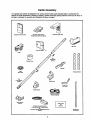
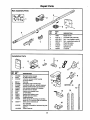
Carton Inventory
Your garage door opener is packagedin two cartons which contain parts illustratedbelow, Accessories will
depend on model purchased. If anythingis missing, carefully check the packing material. Parts may be "stuck"in
the foam. Hardware for assembly and installationis shown on page 7.
StandardControlConsole
Sacurlt_
Security@Three-Function
Remote Contml with Visor Clip (2)
Ks/less EnW
Light Lens
Trolley
/
Rail
Center/Back
Sact_ne
Spre<:ketCover
Chain
Idter Pulley
/
Hanging Brackets
Rml
Front (header)
Sactlon
J
Door Bracket
Cu_
Door
A,'m Section
Header Bracket
2-Co_luctor Bell Wire
White & White/ned
Safety Sensor
Bracket
==%
(2) Safety Reversing Sensors
(I Sending Eye and 1 Receiving Eye)
vim
2-Conductor White & White.lack Bell Wire
at_a_ed
6
Safety Labels
and
literature
Straight Door
Arm Section
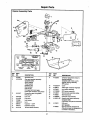
Separate all hardware from the packages In the rail carton and the opener carton, as
shown below, for the assembly end installation procedures.
ASSEMBLY
Lock Nut
1/4"-20 (2)
Lock Washer
3/8" (1)
q
Nut
3/8" (I)
1!/////////)
"n'_i:;
BOR 1/4"-20 x 1-3/4" (2)
Chain Spreader (2)
Tro_ey Tilreaded ShaR (1)
INSTALLATION
Hex Screw
5/16"-18x7/8" (4)
Spacer (2)
©
@ o
Nut
5/16"-18 (8)
Lock Washer
5/16" (7)
Ring
Fastener (3)
l'l,l,l,l,l l,l,l,I>
Lag Screw
5/16"-9xl-5/8" (2)
5/16"-18X2-1/2" (2)
Lag Screw
5/16"-18xl-7/8" (2)
Screw
6ABx1-1/4" (2)
ol}
CJevis Pin
5/16"x1-1/2" (1)
SAFETY
REVERSING
Catdage Bo_t
1/4"-20Xl/2" (2)
Dry Wag
Anchors (2)
o1
Clevis Pin
5/16"x1" (1)
Clevis Pin
5/16"xi-1/4" (1)
SENSOR
Wing Nut (2)
Screw
6-32xl" (2)
Insulated
Staples (20)
Insuleted
Staples (10)
Assembly Section: Pages 8 - 11
To avoid installation difficulties, do not run the garage door opener until instructed to do so.
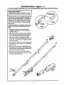
Assembly Step 1
Assemble
the Rail & Install the Trolley
The front rail has a cut out "window'at the door end
(see illustration). The hole above this window Is
larger on the top of the rail than on the bottom.A
smaller hole 3-1/2" away is close to the rail edge.
The back rail has a similar hole close to the edge,
about 4-3/4" from the far end. A 3-piece rail uses
two back rails.
Preferred assembly is to position the rails right
side up, with the small holes along the same
edge.
1. Remove the straight door arm and clevis pin
packaged inside the front rail and set aside for
InstallationStep 12.
2. Align the rail sections on a flat surface exactly as
shown and slide the tapered ends into the larger
ones. Tabs along the side will lock intoplace.
3, Place the powerhead on packing material to
protectthe cover, and rest the back end of the rail
on top. For convenience, put a support under the
front end of the rail.
/
4. As a temporary trolley stop, clamp a locking pliers
onto the rail, 8" from the center of the idler pulley
hole, as shown.
5. Check to be sure there are 4 black plasticwear
pads inside the inner trolley. If they became loose
during shipping,check all packing material. Snap
them back intoposition as shown.
6. Connect the inner and outer trolleys as shown.
7. Slide the trolley assembly along the rail from the
back end to the locked pliers.
/
Assembly
Step 2
Fasten the Rail to the Opener
• Insert a 1/4"-20xl-3/4 bolt into the cover
protectionbolt hole on the back end of the railas
shown. Tighten securely with a 1/4"-20 lock nut.
• Remove the two screws from the top of the
opener.
• Attach spreaders to the U bracket by snapping
them into place.
• Place the U bracket, flat side down, on the opener
and align the bracket holes with the screw holes.
Fasten with the previously removed screws.
• Align the rail assembly with the top of the opener,
and slide the rail end onto the U-bracket as far as
it will go.
into Back Slots,
then Snap Tab
Into Front Slot
Covet Protection
Bo_ Hok_
Hardware Shown Actual Size
L_k Nut
1)))))1))!1)
Bolt 1/4"- _0 x 1-3/4
114"-L>0
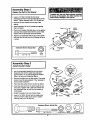
Assembly Step 3
Install
the Idler Pulley
Lay the chain/cable beside the rail, as shown.
Grasp the end with the cable loop and pass
approximately 12" of cable through the window.
Allow it to hang until Assembly Step 5.
Remove the tape from the idler pulley. The inside
center shouldbe pre-graased. If dry, regrease to
ensure proper operation.
Place the idler pulley into the window as shown.
• Insert the idler bolt from the top through the rail
and pulley. Tighten with a 3/8" lock washer and
nut underneath the rail until the lock washer is
compressed.
• Rotate the pulley to be sure it spinsfreely.
Ttoltsy
\
Stop Hole
Idler
Inside
Pulley
Pugey
Cable Loop
Idler Bolt
Bolt 114"-20 x 1-3/4
9
Size
Idler Pulley
_
LOCk Nut 1/4°-20
Nut 3/8"
t
_
• Insert a 1/4"-20xl-3/4 bolt into the trolley stop
hole in the front of the rail as shown. Tighten
securely with a 1/4"-20 lock nut.
Hardware Shown Actual
=
L_k
Wastler 3/8"
Assembly Step 4
Install the Chain/Cable
and Attach the Sprocket Cover
1. Pull the cable aroundthe idler pulley and toward
the trolley.
2. Connect the cable loop to the retaining slot on
the trolley, as shown:
• From below, push pins of master link bar up
through cable loop and trolley slot.
DiSpensing Canon
• Push master linkcap over pins and past pin
notches.
• Slide clip-on springover cap and onto pin
notches until both pins are securely locked in
place.
Leave Chain and Cable
Inside Dis_oenstng
Carton to Prevent Kinking.
\
3. With the trolley against the pliers, dispense the
remainder of the cable/chain along the rail toward
the powerhead and around the sprocket. The
sprocketteeth must engage the chain.
4. Check to make sure the chain is not twisted, then
connect it to the threaded shaft with the
remaining master link.
5. Thread the inner nut and lock washer onto the
the trolley shaft.
Keep Chain and Cable
Taut When Dispensing
6. Insert the trolley threaded shaft through the hole
in the trolley. Be sure the chain is not twiste_.
7. Loosely thread the outer nut onto the trolley
shaft.
,
8. Remove the lockingpliers.
Master
9. Align the tabs on the sprocketcover with the slots
in the mounting plate. Squeeze cover and insert
tabs in slots.
DiilPOn
'"_
: ,
Loop
Link
---_
Spnng
i
Master
_
Link Cap
Link Cap
:
Trolley
:
Threaded :
Shaft
Round
Hole
Idlat
_
,_,
Pin
Notch
Master
Unk Bar
Hble
r_st_e
(_'_-
Master
Link Bat
Sprocket
Cover ---_
,
Front
Tab
Skit
_
,
Opener
SprOcket
Back
Tab
Slot
Mounting
Plate
10
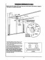
Assembly
Step 5
Tighten the Chain
I
• Spin the inner nut and lock washer down the
threaded shaft, away from the trolley.
Figure I
0=,_ Lo_ r,=_v
NUt
Washer
Shaft
• To tighten the chain, turn outer nut in the direction
shown (Figure 1).
• When the chain is approximately1/2" above the
base of the railat its midpoint,re-tightenthe inner
nut to secure the adjustment.
Sprocket noise can resultif chain is too loose.
When installation is complete,you may notice some
chain droop with the door closed. This is normal. If the
chain returns to the positionshownin Figure 2 when
the door is open, do not re.adjust the chain.
Figure 2
Chain
NOTE:. During future maintenance,ALWA YS pull the
emergency release handle to disconnecttrolley before
adjusting chain.
NOTE: You may noticelooseningof chain after
Adjustment Step 4 (Test the Safety Reverse System).
Check for proper tensionand readjust chain if
necessary. Then repeat AdjustmentStep 4.
Base of Rail
i
i
,,
Mid lengltl of Rail
You have now finished assembling your garage door opener. Please read the following
warnings before proceeding to the installation section:
IMPORTANT INSTALLATION INSTRUCTIONS
I
' &WARNING:
I
I
To reduce the risk of severe injury or death to persons:
1. READ AND FOLLOW ALL INSTALLATION
INSTRUCTIONS.
2. Install only on a properly balanced and lubricated garage door. An improperly balanced door
may not reverse and could result In severe Injury or death. Repelrs to cables, spring assemblies
and other hardware must be made by a professional service person before Installing opener.
3. Disable all locks and remove all ropes connected to the garage door before installing the opener.
Ropes connected to a garage door can cause entanglement and death.
4. If possible, install door opener 7 feet or more above floor with the emergency release handle
mounted 6 feet above the floor.
5. Do not connect the opener to power source until instructed to do so.
6. Locate the Door Control within sight of the door at a minimum height of 5 feet where small
children cannot reach and away from all moving parts of the door.
7. Install the User Safety Instruction Label on the wall adjacent to the door control and the
Maintenance Instruction Label in a prominent location on the inside of the garage door.
8. Upon completion of the installation, the door must reverse when it comes in contact with a
one-inch high object or a 2x4 laid flat on the floor.
9. Do not wear watches, rings or loose clothing while installing or servicing an opener. Jewelry or
loose clothing can be caught In the mechanism of the garage door or the opener.
11
Installation Section: Pages 12- 27
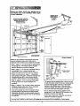
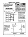
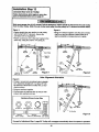
Installation Step I
Determine
Header Bracket Location
If the header bracket Is not rigidly fastened to
a structural support on the header wall or
ceiling, the safety reverse system may not
work properly (see page 30). The door might
not reverse when required, and could cause
serious Injury or death.
The garage door springs, cables, pulleys,
brackets and their hardware are under extreme
tension. Do not attempt to loosen, move or
adjust them yourself. Serious personal Injury
or death could result. Call for professional
garage door service.
Installation procedures vary according to
garage door types. Follow the Instructions
which apply to your door.
-- Header __
Wall
i
Ver_cei
Guideline
Rnished
--
cei_g
2:<4
Structural
• Close the door and mark the inside
verticalcenterline of the garage door.
• Extend the line onto the header wall
above the door.
Remember, you can fasten the
header bracket within 2 feet of the
left or right of the door center on/yif
a torsion spring or center bearing
plate is in the way; or you can attach
it to the ceiling (refer to page 14)
when clearance is mthlmal. (It may
be mounted on the wall upside down
if necessary, to gain approximately
1/2".)
If you need to install the header bracket
on a 2x4 (on wail or ceiling), use lag
screws (not provided) to securely fasten
the 2x4 to structuralsupportsas shown
here and on page 13.
J
Ceiling
• Open your door to the highest
point of travel as shown. Draw
an intersectinghodzontal line
on the header wall 2" above
the high point. This height will
providetravel clearance for the
top edge of the door.
Door clearance brackets are
available for sectional doors
when headroom clearance is
less than 2". See accessory
page 38,
Header
Wall
,,-- 2"
Track
Header
Wall
:--2"
Tr_c_
Highest POint
of Travel
Highest Point
of Trave_
Door
--
Sectional door
with curved track
Proceed to Step 2, page 14.
12
One-piece door
with horizontal track
Read the Safety instructions
on page 12. They also apply to doors without tracks.
Ve_ical
Cemedine
2x4
• Close the door and mark the
inside vertical centerline of
your garage door. Extend the
line onto the header wall
above door.
If headroom clearance is
minimal,you can install the
header bracket on the ceiling.
•See page 14.
• Ifyou need to install the
header bracket on a 2x4 (on
wall or ceiling), use lag screws
(not provided) to securel7
fasten the 2x4 to structural
supportsas shown.
OPTIONAL CElUNG MOUNT
FOR HEADER BRACKET
Header Wall
/
Highest Point
of Traval
/
oo.°-
o
Jamb
Hardware
One-piece door without track
jam b hardware
One-piece door without track
pivot hardware
EXAMPLE
• Open your door to the highest pointof travel as
shown. Measure the distance from the top of the
door to the floor, Subtract the actual height of the
door. Add 8" to the remainder. (See Example).
• Close the door and draw an intersectinghorizontal
line on the header wall at the determined height.
Distance from top of door
(at highest pointof travel) to floor ........................... 92'
Actual height of door............................................. -88..._."
Remainder................................................................ 4"
Add ......................................................................... +8"
If the total number of inches exceeds the height
available In your garage, use the maximum
height possible, or refer to page 14 for ceiling
installation.
Bracket heighton header wall ............................... 12=
(Measure UP from top of CLOSED door.)
Proceed to Step 2, page 14.
13
Install the Header Bracket
Installation Step 2
You can attach the header bracket either to the
wall above the garage door, or to the calling.
Follow the Instructlons which wlU work best for
your particular requlrements.
I
Wall Header Bracket Installatlon
• Center the bracket on the vertical guideline with
the bottom edge of the bracket on the horizontal
line as shown (with the arrow pointingtoward the
ceiling).
Header
Bracket
• Mark the vertical set of bracket holes. Drill3/16"
pilot holes and fasten the bracket securely to a
structuralsupportwith the hardware provided.
2x4
Structura_
Support
Vertical
Wall Mount
Center
Line
Spnng
I_t_nal
Mounting Holes
_. ";
Vertical
Center
Line
Highest Point of
Garage Ooor Travel
Hardware Shown Actual Size
I'!'I'L'o!!IIIll I'1
5/16"-9XI
-P,_"
Ceiling Header Bracket Installation
• Extend the vertical guideline onto the ceiling as
shown,
• Center the bracket on the vertical mark, no more
than 6" from the wall. Make sure the arrow is
pointingtoward the wall. The bracket can be
mounted flush against the ceiling when clearance
is minimal.
•
Mark the side holes. Drill3/t6 u pilot holesand
fasten bracket securely to a structural supportwith
the hardware provided.
Ce_ling
Mounting Holes
Door Spdng
Verltcal
Center Line
14
Attach the Rail to the Header Bracket
Installation Step 3
I
NOTE: (Optional) Hqthan existing Crafsman
installation, you may re-use the old header bracket
with the two plastic spacers included in the hardware
bag. Place the spacers inside the bracket on each
side of the rail, as illustratacL
• Positionthe opener on the garage floor below the
header bracket. Use packing material as a
protectivebase.
If the door spring Is In the way you'll need help.
Have someone hold the opener securely on a
temporary support to allow the rail to clear the
spring.
• Positionthe front railend within the header bracket
and join with a 5/16"xl-1/2" clevis pin as shown.
Header BraCket
• Insert a ring fastener to secure.
\1
\1
Bracket
\1
\1
\1
\1
\1
\_1
Moun_ng
Hole
Existing
Header Bracket
'
0
Spacer
M
Moun_ng
H_e
M
\1
M
OPTION WITH
EXISTING CRAFTSMAN
_NSTALLATION
Hardware Shown Actual Size
©
Clevis Pin 5/16"xl -1/2"
15
Ring fastener
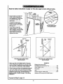
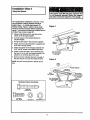
Installation Step 4
Position the Opener
Follow Instructions which apply to your door
type as illustrated.
A 2x4 laid flat Is convenient for setting an Ideal
door-to-T-rail distance.
Outer Trolley
• Raise the opener onto a stepladderas shown. You
will need help at this point if the ladder is not tall
enough.
• Open the door all the way and place a 2x4 laid flat
on the top section beneath the rail.
If the top panel hits the trolley when you raise
the door, pull down on the trolley release arm to
disconnect the Inner and outer sections. The
trolley can remain disconnected until Step 12 is
completed.
Trolley
i
i
Trolley
I ONE_PiE,€_r
without Track i
• With the door fully open and parallel to the floor,
measure the distance from the floor to the top of
the door.
• Using a stepladder as a support, raise the opener
to this height (it will be at a slightangle as shown).
• The top of the door should be level with the top of
the opener. Do not positionthe opener more than
2" above this point.
16
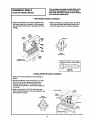
Installation Step 5
I
I
Hang the Opener
Two representative installationsare shown, Yours
may be different. Hanging brackets should be
angled, Figure 1, to provide rigidsupport. On
finished ceilings, Figure 2, attach a sturdy metal
bracket to structuralsupports before installingthe
opener. The bracket and fastening hardware are not
>rovided.See accessory page 38.
1. Measure the distance from eachside of the
opener to the structuralsupport.
Figure 1
upports
2. Cut both pieces of the hanging bracket to
required lengths.
'
3. Drill 3/16" pilotholes in the structuralsupports.
MeasJJ_ _
4. Attach one end of each bracket to a support with
5/16"-18xl-7/8" lag screws.
5. Fasten the opener to the hanging brackets with
5116"-18x7/8"screws, lock washers and nuts.
6. Check to make sure the T-rail is centered over
the door (or in line with the header bracket if the
bracket is not centered above the door).
5,'16".18x7/8" Screw
5/16" Lock Washer
5/16"-18 Nut
7. Remove the 2x4. Operate the door manually. If
the door hitsthe rail, raise the header bracket.
Figure 2
NOTE: Do NOTconnect power to opener at this
time.
Hidden
.s_. ........
........
"""
. ....
- ";'-_""
Sracke!
"".
5/1 65;1L6oc_,
W,sher
l'l'llr'l'lLl'l'!'l'l'l
LagScrew
5/16"18xl-7/8"
Hex _ew
5/16"- 18x7/8"
Nut 5/16"-18
L0Ck Washer 5/16"
17
"" ""
.... ;;;
;'-.'--'_"....
" RNISHED CEIUNG--
Lag Screws •
"":':':'"_ t P
5/16"-18x'7/8" "'Screw
Hardware Shown Actual Size
. - -"
\
5/16" Lock Washer
\
5/16"-18 Nut
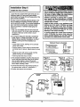
Install
the Door Step
Control6
Installation
I
Do not connect to live electrical wiring. Connect
only to 24 Volt low voltage w/ms. Connection to
live wires or higher voltage may cause serious
injury from shock, bum or electrocution.
Children operating or playing with a garage
door opener can injure themselves or others.
The garage door could close and cause
serious injury or death.
Install the door control (or any additional push
buttons) out of the reach of children and away
from all moving parts of the door and door
hardware, but where the garage door Is visible.
Do not allow children to operate the push
button(e) or the remote control(s).
A moving garage door could injure someone
under it. Activate the opener only when the
door is properly adjusted, you can see It clearly,
and there are no obstructions to door travel.
Locate the door control within sight of the door at a
minimum height of 5 feet where small children
cannot reach, and away from all movingparts of the
door and door hardware.
The door controlis typically attached directly to the
wall. If installinginto drywall, drill5/32" holes and
use the anchors provided. Forpre-wiredinstalla#ons
(as in new home construction), Console models
may be mounted to a standard singlegang box
(Figure 2).
1. Strip 1/4" of insulationfrom one end of the bell
wire and connect it to the two screw terminals on
the back of the door control:white to 2 and
white/red to 1.
2. Pry off cover along one side with a screwdriver
blade (Figure 1). Fasten with 6ABx1-1/4" selftapping screws (standard installation)or 6-32xl"
machine screws (pre-wired installation) as
follows:
Hardware Shown Actual Size
• Install bottom screw, allowing 1/8" to protrude
above wall surface.
_
• Positionbottom of door controlon screw head
and slide down to secure, Adjust screw for snug
fit,
ContrOl Console (std installation)
• Install top screw with care to avoid cracking
plastichousing. Do not overtighten.
• Insert top tabs and snap on cover.
Control
3. (For standard installation only) Run the bell wire
up the wall and across the ceiling to the opener.
Use insulated staples to secure the wire in
several places. Be careful not to pierce the wire
with a staple, creating a short.
4. Connect the bell wire to the terminal screws on
the opener panel: white to 2; white/red to 1.
5. Position the antenna wire as shown.
Console
(pre*wirecl)
Cry Wall
Figure 1
Top.Tabs ."
."
Bell
Wire
of Opener
,,_j_
INSTALLATION
Here
Twist
2-Conductor
Bell Wke
18
PRE-WIRED
_-----_=To Remove,
F___
Insert
STANDARD
CONTROL
CONSOLE
Allcb, ors
Figure 2
REMOVE & REPLACE COVER
To Replace,
Insulated
Staples
0
_
24 Volt'
2-Conductor
Bell Wire
6.AttachtheUserSafetyInstruction
labeltothewall
nearthedoorcontrol,and the Maintenance
Do NOT connect thepower and operate the
openerst this time. The trolley will travel to the
full open position but will not return to the
close position until the sensor beam Is
connected and properly aligned.
See Safety Reversing Sensor Instructions
beginning on page 21.
Instructionlabel in a prominent locationon the
inside of the garage door.
Page 32 explains how to use the door control.
Installation
Step 7
Install the Light and the Lens
Install
I
the light
• Install a 75 watt maximum light bulb in the socket.
The light willturn ON and remain lit for
approximately 4-1/2 minuteswhen power is
connected. Then the light willturn OFF.
Light
Lens
!
• If the bulb burns out prematurely due to vibration,
replace it with a standard neck "Garage Door
Opener" bulb.
Lens
Guide
Install the lens
• For convenience, the lens may be installed
after Adjustment Step 4 on page 30.
• Apply slight pressure on the sides of the lens and
slide the tabs intothe slots in the end panel.
• Reverse the procedure to remove the lens.
Installation Step 8
Attach the Emergency
Release
Rope and Handle
Do not use the red handle to pull the door
open or closed. The rope knot could become
untied and you could fall. Use the emergency
release only to disengage the trolley and, if
possible, only when the door is closed.
Garage doors are heavy. If the door Is open
when the handle is pulled, the door could
close inadvertently
if It Is not properly
balanced. Serious Injury may result to persons
under the door. Make sure the doorway Is clear
of persons and obstructions before pulling
handle when door is open.
• Thread one end of the rope through the hole in the
top of the red handle so "NOTICE" reads dght side
up as shown. Secure with an overhand knot, at
least 1" from the end of the rope to prevent
slipping.
• Thread the other end of the rope through the hole
in the release arm of the outer trolley.
• Adjust rope length so the handle is 6 feet above
the floor. Secure with an overhand knot.
If it is necessary to cut the rope, heat seal the
cut end with a match or lighter to prevent
unraveling.
(_
19
Release Handle
Installation Step 9
Electrical Requirements
J
I
To reduce the risk of electric shock, your garage
door opener has a groundingtype plug with a third
grounding pin. This plug will onlyfit intoa grounding
type outlet.
To prevent electrocution or fire, Installation
and wiring must be In compliance with local
electrical and building codes.
Do NOTuse an extension cord, 2-wire adapter,
or change the plug In any way to make it fit
your outlet.
If the plug doesn't fit intothe outlet you have,
contact a qualifiedelectricianto installthe proper
outlet.
7"0avoid
do
not runInstallation
the opener difficulties,
at this time.
I
Right
If permanent
Wrong
wiring is required by your local code, refer to the following procedure:
Permanent
Wiring
Connections
To make a permanent connection through the
7/8" diameter hole in the top of the opener
(according to local code):
Remove the opener cover screws and set the
cover aside.
Ground Tab
teen
Remove the attached 3-prong cord.
_tew
Connect the black (line) wire to the screw on the
brass terminal; the white (neutral) wire to the
screw on the silverterminal; and the ground wire
to the green ground screw. The opener muat be
grounded.
Reinstall the cover.
Black
.- Wire
Wire
White Wire
Wire
To avoid installation difficulties,
do not run the opener at this time.
J
I
2O
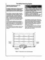
The Safety Reversing System
IMPORTANT INFORMATION ABOUT THE
SAFETY REVERSING SENSOR
The safety reversing sensor mustbe connected
and aligned correctly before the garage door
opener will move in the down direction. This Is a
required safety device and cannot be disabled.
Without # properly working safety reversing
sensor, persons (particularly children) could
be Injured or killed by a closing garage door.
Read and follow all Instructions.
To protect small children, Install the safety
reversing sensor so that the beam will be
between 4 - 6" above the garage floor.
Disconnect power to the garage door opener
before Installing the safety reversing sensor.
When properly connected and aligned, the safety
reversingsensor will detect an obstacle in the path
of its electronic beam. The sending eye (with an
orange indicator light) transmitsan invisiblelight
beam to the receiving eye (with a green indicator
light).If an obstructionbreaks the light beam while
the door is closing, the door will stop and reverse to
full open position, and the opener light will flash
10 times.
If it is necessary to mount the unitson the wall, the
bracketsmust be securelyfastened to a solid surface
such as the wall framing. Extension brackets (see
accessories)are available if needed. If installingin
masonryconstruction,add a piece of wood at each
locationto avoid drillingextra holes in masonry if
rspositioningis necessary.
The invisiblelightbeam path must be unobstructed.
No part of the gai'age door (or door tracks, springs,
hinges,milers or other hardware) may interrupt the
beam while the door is ctosing.
The units must be installed inside the garage so
that the sending and receivingeyes face each other
across the door, between 4 - 6" above the floor.
Either can be installedon the left or right of the door
as long as the sun never shines directly into the
receivingeye lens.
The mounting brackets are designed to clip onto the
track of sectional garage doors without additional
hardware.
Sensor Beam
Sensor Beam
4-6" max.
above floor
4*6" max.
above floor
\\
I
Invisible Ught Beam
Protection Area
Figure 1 : Facing the door from Inside the garage
21
Figure 2
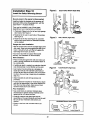
Installation Step 10
Install
the Safety
Reversing
OOOR TRACK MOUNT (Right Side)
Sensor
Be sure power to the opener Is disconnected.
:
Install and align the brackets so the sensors will
face each other across the garage door, with the
beam from 4 - 6" above the #oor.
They may be installedin one of three ways,
depending on your requirements, as follows.
L_
Sensor
Bracket
1. (Preferred) Clipped onto the left and right garage
door tracks. See Figure 2.
2. Fastened to the wall on each side of the garage.
See Figure 3.
Figure 3
3. Fastened to the floor (see Figure 4). Concrete
anchors and wood blocksor extension brackets
will be needed.
WALL MOUNT(RightSide)
VVJ
Garage door track Installation:
II
• Slip the curved arms over the rounded edge of the
door track. Snap into place against the side of the
track. It should lie flush, with the lip hugging the
back edge of the track, as shown.
I -..
(See Accessories)
I
I_
(P._dedwith
Extens_n
If your door track will not supportthe bracket
securely, wall installationis recommended.
Wall installation:
Sensor
• Place the bracket against the wall and make sure
there is enough clearance for the sensor beam to
be unobstructed.
(Provided with
Extension Bracket)
• If additionaldepth is needed, an extension bracket
(see Accessories) or wood blocks can be used.
Figure 4
• Use bracket mounting holes as a template to
locate and drill (2) 3/16" diameter pilot holes on
the wall at each side of the door, from 4-6" above
the floor. (See warning at beginning of Installation
Step 10.)
Lens
light
FLOOR MOUNT (Right Side)
Lens
Sensor
Bracket
Ind_a_r
light
(Prov_edwffh
Extension Bmcket)
• Attach brackets to wall with lag screws (not
provided).
• If using extension brackets or wood blocks, adjust
right and left assemblies to the same distance out
from the mounting surface. Make sure all door
hardware obstructions are cleared.
(notpmvided)
Extension
Bracket
(See Accessories)
Floor installation:
• Use wood blocksor extension brackets (see
Accessones) to elevate sensor brackets so the
lenses will be 4-6" above the floor.
• Carefully measure and place right and left
assemblies at the same distance out from the wall.
Be sure all door hardware obstructionsare
cleared.
Hardware Shown Actual Size
• Fasten to the floor with concrete anchors as
shown,
1/4"-2OXl/2" (2)
22
Wing Nut (21
Insulated Staples (20)
MounUng
and Wiring the Safety Sensors
• Slide a I14"-20xi/2' cardagebolthead intothe slot
on bothsensors.Use wing nutsto fastensensorsto
brackets,with lenses pointingtowardeach other
acrossthe door. Be sure the lens is notobstructedby
a bracket extension. See Figure 5.
• Fingertightenthe sensorwingnuts.
• Run the wires from both sensorsto the opener.Use
insulatedstaples to secure wire to wall and ceiling.
• Strip 114"of Insulationfrom eachset ofwires.
Separate white and white/blackwiressufficientlyto
connectto the opener terminalscrews: whiteto 2
and white/blackto 3.
Aligning the Safety Sensors
• Plug in the opener.The indicatorlightsin boththe
sendingand receivingeyes willglowsteadilyif wiring
connectionsand alignmentare correct.
The sandingeye orange indicatorlightwillglow
regardlessof alignmentor obstruction.If the green
indicatorlightin the receiving eye is off, dim,or
flickering(and the invisiblelightbeam pathis not
obstructed),alignmentis required.
Loosenthe sendingeye wing nutand readjust,
aimingdirectly at the receivingeye. Lock in place.
Loosenthe reoeivingeye wingnut and adjustsensor
vertioallyand/orhorizontallyuntilit receivesthe
sender'sbeam. When the green indicatorlightglows
steadily,tightenthe wing nut.
Figure 5
114 2OXI/2
""_
Trouble Shooting the Safety Sensors
1. If the sendingeye indicatorlightdoes not glow
steadilya_erinstallation,checkfor:
• Electricpowerto the opener.
• A shortin thewhiteor white/blackwires. These can
occurat staples,or at screwterminalconnections.
• Incorrectwiringbetweensensorsand opener.
• A brokenwire.
2. Ifthe sendingeye indicatorlightglowssteadilybutthe
receivingeye indicatorlight doesn't:
• Check alignment.
• Checkfor a brokenwire to the receivingeye.
3. If the receivingeye indicatorlightis dim, realigneither
sensor.
NOTE: Whentheinvisible beam path is obstructedor
misalignedwhile thedooris closing,the door will
reverse. If the dooris alreadyopen, it will not close. The
openerlights v_ll#ash 10 times.(If bulbsare not
installed, 10 dicks canbe heard.) See page 21.
Figure 6
Door Control
sensor
Connections
f
OPENER TERMINAL SCREWS
Sensor
Pro_ectio_ Area
23
Installation Step 11
Fasten Door Bracket
Follow Instructions which apply to your door
type as Illustrated below or on page 25.
A horizontal brace should be long enough to be secured to 2 vertical supports. A vertical brace should
cover the height of the top panel.
The Illustration shows one piece of angle Iron as the horizontal brace. For the vertical brace, 2 pieces of
angle iron are used to create s "U"-shaped support. The best solution Is to check with your garage door
manufacturer for an opener installation door reinforcement klL
• Center the door bracket on the previously marked
vertical guideline used for the header bracket
installation. Note the correct LIPplacement, as
stamped Inside the bracket.
• Positionthe bracket on the face of the door within
the following limits:
A) The top edge of the bracket 2"-4" below the top
edge of the door.
_
_..._._.,
_'_'/
Hardware Shown Actual Size
©
B) The top edge of the bracket directly below any
structuralsupport across the top of the door.
©
Nut _16"-18
LockWasher
• Mark and ddll 5/16" left and right fastening holes,
Secure the bracket as shown in Figure t if there is
vertical reinforcement.
If your installationdoesn't requirevertical reinforcement but does need top and bottomfastening holes
for the door bracket, fasten as shown in Figure 2.
S/16"-18
24
x 2-I/2"
5/16 °
Please read and comply with the warnings and reinforcement
They apply to one-piece doors also.
Instructions on page 24.
HeaderW_II
2x4 Support
Header
Finished Ceiling --
Door
Bracket
Horizontal and vertical reinforcement is
=. needed for t_ghtweigh!garage doors
door with
glass panel, etc.). (Not Provided)
Placement
of Door
BraCket
Vertical
Centedine of
Garage Door
L
LOCkWasher
5/16"
TOp of Door
Door
--.
(Inside Garage)
3racket
of Door
Top
Edge
I
.
Placement
Optional
For a door with no
exposed framing or for
the optiofla) instaliatfon,
use 5/16"xI-1/_" lag
screws (not provided)
• Center the bracket on the top of the door, in line
with the header bracket as shown. Mark holes.
Hardware Shown Actual Size
• Drill5/16" pilot holes and fasten the door bracket
with hardware provided.
©
If the door has no exposed framing, drill3/16" pilot
holes and fasten the bracket with 5/16"x1-1/2" lag
screws (not provided) to the top of the door.
The door bracket may be Installed on the top
edge of the door If required for your Installation.
(Refer to the dotted line optional placement
drawing.) Drill 3/16" pilot holes and substitute
5/16"x1-1/2" lag screws (not provided) to fasten
the bracket to the door.
©
lllll!lllllllllllllllllltlllllllfllD
Nut 5/16"-18
LockWasher
Carnage _lt
5/16"-18 x 2-1/2"
25
5/16"
Installation Step 12
Connect Door Arm to Trolley
Follow Instructions which apply to your door
type as Illustrated below and on page 27.
Make sure garage door Is fully closed. Pull the emergency release handle to disconnect the outer trolley
from the inner trolley. Slide the outer trolley back (away from the pulley) for 8" minimum as shown below,
Figure 1:
Figure 2:
• Fasten straightdoor arm section to outer trolley
with the the 5/16"xl" clevis pin. Secure the
connectionwith a ring fastener.
• Fasten curved door arm to the door bracket in the
•same way, using the 5/16_xl - 1/4" clevispin.
• Bringarm sectionstogether. Find two pairs of holes
that line up end join sections. Select holes as far
apart as _ossible to increase door arm rigidity.
Outer Trolley
5/16"x1"
"_
Screws
Door Arm
"_
Clevis Pin
5,'16"x1-1/4"
Figure I
Door Arm
5/16"-18x7/8"
Figure 2
Door Bracket
Hole Alignment
Alternative
Figure 3:
• If holes in curved arm are aboveholes in straight
arm, disconnect straightarm, Cut about 6" from
the solidend. Reconnect to trolley with cut end
down as shown,
_ Bringarm sections together.
Find two pairs of holes that line up and join with
screws, lock washers and nuts.
Hardware
Shown Actual Size
©©o
Nut 5/16"-18
Lock WaSher 5/16"
5/16"x1" (Trolley)
"_
Screws
5/16"-18x7/8"
Ring Fastener
Clevis Pin
5/16"x 1-1/4" (Door Bracket)
Figure
Hex Screw
5/16"-18x7/8"
3
Proceed to Adjustment Step 1, page 28. Trolley will re-engage automatically when the opener Is operated.
26
AssembletheDoorAnn:
• Fastenthestraight
andcurveddoorarm sections
P_g
Door
together to the longest possiblelength (with a 2 or
3 hole overlap).
Lock
Washers
5/16"
• With the door closed, connectthe straight door arm
sectionto the door bracket with the 5/16"x1-1/4"
clevis pin,
Nuts
5/1
S_ugl
Arm
Screws
5/16"-18x7/8
• Secure with a ringfastener.
DoorArm
On one-piecedoom, beforeconnectingthe door arm tothe trolleythe travel limitsmustbe adjusted.Limitadjustment
screws are located on the left side panel as shown on page 28. Follow adjustment proceduresbelow.
FULLY CLOSED POSITION
_nner Trol Lley
Door An11
_='t." _......
_Q_
O4JterTrolley
ConnectorHOLe
1
Door
FULLY OPEN POSITION
iI I
_ .......
:Closed
Outer TroUey
Connector Hole
/
T
OpenDoor
I
Coor with
Backward
Coor Arm
Slant
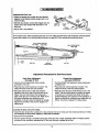
Adjustment Procedures for One-Piece Doors
Open Door Adjustment:
Decrease UP limit
Closed Door Adjustment:
Decrease DOWN limit
• Turn the UP I=mltadjustment screw counterclockwise 5-1/2 rums.
• Turn the DOWN limit adjustmentscrew clockw=se5
complete turns
• Press the Door Control push bar or button.The
trolley will travel to the fully open position.
• Manually raise the door to the open position
(parallel to the floor), and hftthe door arm to the
trolley.The arm shouldtouch the trolley just in
back of the door arm connector hole. Refer to the
fully open trolley/doorarm positions in the
Illustration.If the arm does not extend far enough,
adjust the hmltfurther. One full turn equals 2" of
trolley travel.
• Press the Door Control push bar or button.The
trolley wdl travel to the fully closed position.
• Manuallyclose the door and lift the door arm to the
trolley The arm shouldtouchthe trolleylUStahead
of the door arm connectorhole. Refer to the fully
closed trolley/doorarm positionsin the illustration.If
the arm =sbehind the connectorhole, adjust the hmit
further One full turn equals 2"of trolley travel.
Connect the door arm to the trolley.
• Close the door and join the curved arm to the connector hole in the trolley with the rematmngclevis pin. It may
be necessary to lift the door slightly to make the connection.
• Secure with a ring fastener
• Run the opener through a complete travel cycle. If the door has a slight "backward"slant in full open position
as shown in the dlustration,decrease the UP limituntil the door is parallelto the floor.
27
Adjustment Section: Pages 28 - 30
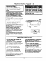
Adjustment Step I
Adjust
the UP and DOWN
Limits
Improper adjustment of the travel limits will
interfere with the proper operation of the safety
reverse system. The door might not reverse
properly when required and could seriously
Injure or kill someone under It. Test the safety
reverse system following all adjustments to the
travel limits. See page 30.
Do not make any limit adjustments until the
safety reversing sensors are completely
Installed.
Limit adjustment settings regulate the points at
which the door will stop when moving up or down,
If anything interferes with the door's upward travel, it
wiI! stop. If anything interferes with the door's
downward travel (including bindingor unbalanced
doors), it will reverse.
To operate the opener, press the Door Control push
bar or button. Run the opener through a complete
travel cycle.
Urn_
Adjustment
Screws
• Does the door open and close completely?
• Does the door stay closed and not reverse
unintentionallywhen fully closed?
If your door passes both of these tests, no limit
adjustments are necessary unless the reversingtest
fails (See page 30).
Cover
Protection
Adjustment procedures are outlined below.
Read the procedures carefully before
proceeding to Adjustment Step 2. Use a
screwdriver to make limit adjustments. Run the
opener through a complete travel cycle after
each adjustment.
Left Side Panel
Bolt
NOTE: Repeated operation of the opener during
adjustmentprocedures may cause the motor to
overheat and shut off. Simply wait 15 minutes and
try again.
Adiustment Label
How and When to Adjust the Limits
• If the door does not open completely, but
opens atleastflve feet:
• If the opener reverses In fully closed position:
Decrease downtravel.Turn the DOWN limit
adjustment screwclockwise. One turn equals 2" of
travel.
Increase up travel. Turn the UP limit adjustment
screw clockwise.One turn equals 2" of travel.
NOTE: To prevent the trolley from hiring the cover
protection bolt, keep a minimum distance of 2-4"
between the trolley and the bolt.
• If the door revereeswhen closing and
there Is no visible interference to travel cycle:
Adjust the UP (open) force as explained in
Adjustment Step 2.
If the opener lights are flashing, the Safety
Reversing Sensors are either not installed,
misaligned, or obstructed.See Troubleshooting,
page 23.
• If the door does not close complete/y:
Increase downtravel. Turn the DOWN limit
adjustment screw counterclockwise. One turn
equals 2" of travel.
Test the door for binding:Pull the emergency
release handle. Manuallyopen and close the door. If
the door is binding,call for garage door service. If
the door is not bindingor unbalanced,adjust the
DOWN (close) force. See AdjustmentStep 2.
• If door does not open at least 5 feet:
If the door stillwon't close completely and the trolley
bumps intothe trolley stop bolt (see page 4 or 5), try
lengthening the door arm (see page 26) and
decreasing the down limit.
28
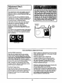
Adjustment Step 2
I
I
Adjust the Force
Force adjustment controls are located on the back
_anel of the opener. Force adjustment settings
regulate the amount of power required to open and
close the door.
The door will stopin the up direction if anything
interferes with its travel. The door will reverse in the
down direction if anything interfereswith its travel
(includingbinding or unbalanced doors).
If the forces are set too light,door travel may be
interrupted by nuisance reversals in the down
direction and stops in the up direction.
Weather conditions can affect the door
movement, so occasional adjustment may be
needed.
Too much force on the door will Interfere witt
the proper operation of the safety reverse
system. The door might not reverse properly
when required and could seriously Injure or Idll
someone under It. Do not Increase the force
beyond the minimum amount required to close
the door. Do not use the force adjustments to
compensate for a binding or sticking garage
door. Test the safety reverse system following
all adjustments to force levels. See page 30.
Backpanelof
door opener
\
Force
Adjustment
Contr_
The maximum force adjustment range is 260 degrees,
about 3/4 of a complete turn. Do not force controls
beyond that point. Turn force adjustment controls
with a screwdriver.
Adjustment Labe4
How and When
to Adjust
Test the DOWN (close) force
the Forces
Make 10 degree tum adjustmentsuntilthe door stops
easily.After each adjustment, runthe opener through
a complete travel cycle.
If the door doesn't open at leest5 feet
Grasp the door bottom when the door is about
halfway through DOWN (close) travel. The door
should reverse. Reversal halfway through down
travel does not guarantee reversal on a two-inch
obstruction. Seepage 30. If the door is hard to
hold or doesn't reverse, decrease the DOWN (close)
force by turning the control counterclockwise.
Increase UP (Open) force by turningthe control
clockwise. Make 10 degree turn adjustmentsuntil
door openscompletely. Re-adjust the UP limitif
necessary.After each adjustment,run the opener
through a complete travel cycle.
Make 10 degree turn adjustments until the door
reverses normally. After each adjustment, run the
opener through a complete cycle.
If the door reverses during the down (close) cycle
and the opener lights aren't flashing
Increase DOWN (close) force by turningthe control
clockwise. Make 10 degree turn adjustmentsuntil the
door completes a close cycle. Aftereach adjustment,
runthe opener througha complete travel cycle. Do
not increase the force beyond the minimum
amount required to close the door.
Test the UP (open) force
Grasp the door bottom when the door is about
halfway through UP (open) travel. The door should
stop. If the door is hard to hold or doesn't stop,
decrease UP (open) force by turningthe control
counterclockwise,
29
Adjustment Step 3
Test The Safety Reversing
Sensor
I
• Press the remote controlpush buttonto open the
door.
• Place the opener carton in the path of the door.
• Press the remote control push button to close the
door. The door will not move more than an inch,
and the opener light will/lash.
Professional service Is required If the opener
closes the door when the safety reversing
sensor Is obstructed.
I
[ if
The garage door opener will not close from a
remote control if the Indicator light in either
sensor is off(alerting you to the fact that the
sensor is mlsaligned or obstructed).
In
I
Io[ ]
11il
The garage door can be closed by pressing and
holdingthe Door Control push bar or button until
down travel is completed.
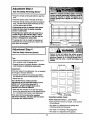
Adjustment Step 4
Test the Safety
Reverse
System
I
Test:
• Place a one-inch board (or a 2x4 laid flat) on the
floor, centered under the garage door.
Operate the door in the down direction. The door
must reverse on striking the obstruction.
L
Adjustment:
If the door stops on the obstruction,it is not traveling
far enough in the down direction.
• Increase the DOWN limit by turning the DOWN
limitadjustment screw counterclockwise1/4 turn.
• Repeat the test.
On a sectional door, make sure limit
adjustments do not cause the trolley to move
within 2-1/2" of the trolley stop boll If
necessary, lengthen straight door arm to
maintain this minimum distance.
• When the door reverses on the one-inch board,
remove the obstructionand run the opener through
3 or 4 completetravel cycles to test adjustment.
If the door will not reverse after repeated
adjustment attempts, call Sears Service Center
for garage door opener service.
Important safety check
Repeat Adjustment Steps 1, 2 and 4 after:
• Each adjustment of door arm length, force controls
or limit controls.
• Any repair to or adjustmentof the garage door
(including springsand hardware).
• Any repair to or bucklingof the garage floor.
• Any repair to or adjustmentof the opener.
3O
IMPORTANT
F
SAFETY INSTRUCTIONS
To reduce the risk of severe injury or death to persons:
1. READ AND FOLLOW ALL INSTRUCTIONS.
5. If possible, use the emergency release only
when the door is In a closed position. Caution
should be taken whenever the disconnect cord
is actuated with the door open. Weak or broken
springs may cause the door to fall rapidly,
causing Injury or death to persons.
6. KEEP GARAGE DOORS PROPERLY
BALANCED. See page 3. An improperly
balanced door may not reverse when required
and could result in severe injury or death.
Repairs to cables, spring assemblies and other
hardware must be made by a professional
garage door person.
2. Do not permit children either to operate or to
play with the opener. Keep remote control in a
location Inaccessible to children.
3. Operate opener only when the door is In full
view and free from any obstruction. Keep the
door in sight until it is completely closed. NO
ONE SHOULD CROSS THE PATH OF THE
MOVING DOOR.
4. Check safety reversal system monthly. See
page 30. The garage door MUSTreverse on
contact with a one-inch (or a 2x4 board laid
flat) object placed on the floor. If an adjustment
is made to either the force or the limit of travel,
both adjustments may be needed and the
safety reversal system must be checked.
Failure to properly adjust the opener may
result in severe Injury or death.
7. Disconnect the electric power to the garage
door opener before making any rspalrs or
removing the covers.
8.SAVE THESE INSTRUCTIONS.
Care of Your Opener
Limit and force adjustment controls
The remote control
3-FUNCTION
Limit Controls
Force Controls
Adjustment Label
(Located on the left side pane4)
Adjustment Label
(Located on the tight side panel)
The lithiumbattery should
o_this,be
first to avoid
produce power for up to
crac_ng
5 years. To replace battery,
use the visor clip or screwdriver
blade to pry open the case, as
shown. (=Open"location is
stamped on back of transmitter case.) Insert battery
positive side down,
Replace cover as follows. 3-Func_'onremote: Insert
the 3 tabs at the oppositeend and snap shut.
Weather conditions may cause some minor
changes in door operation requiring some readjustments, particularly during the first year of
operation.
Pages 28 and 29 refer to the limitand force
adjustments. Only a screwdriveris required. Follow
the instructionscarefully.
Dispose of old batteries properly.
WARNING .
Repeat the safety reverse test (page 30) after any
adjustment of limits or force.
r
Maintenance
Keep batteries away from small children.
swallowed, promptly notify doctor.
,iI
Schedule
Once a Month
Twice a Year
Manually operate door. If it is unbalanced or
binding, call for professionalgarage door service.
Check chain tension. Disconnecttrolley first.
Adjust if necessary (See page 11).
Once a Year
Check to be sure door opens & closes fully.
Adjust limitsand/or force if necessary.
(See pages 28 and 29.)
Oil door rollers, bearings and hinges. The opener
does not require additional lubrication.Do not
grease the door tracks.
Repeat the safety reverse test. Make any
necessary adjustments (See page 30).
31
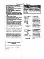
Operation of Your Opener
Activate the opener with any of the following:
• The Remote Control: Hold push button down until
the door startsto move.
• The Door Control: Hold push button down until
the door startsto move.
Weak or broken springs could allow an open
door to fall (either rapidly or unexpectedly),
resu/tlng In serious Injury, death or property
damage. If posslble, use the emergency
release rope and handle on/ywhen the door Is
fully closed.
• The Outdoor Key Switch or Keyless Entry.
(See Accessories)
When the opener Is activated with the safety
reversing sensor installed and correctly aligned:
1. If open, the door willclose. If closed, the door will
open.
2. If closing, the door will reverse.
3. If opening, the door will stop (allowing space for
entry and exit of pets and for fresh air).
4. If the door has been stopped in a partiallyopen
position, it will close.
Release arm
5. If obstructedwhile closing, the door will reverse.
Emergency
Release Handle
(Pug Down)
6. If obstructedwhile opening, the door will stop.
7. The garage doorwill reverse in the closingcycle,
and the opener lights will blink for 5 seconds,
when the invisiblebeam is broken. If fullyopen, the
door willnot close when the beam is broken.The
sensorhas no effect in the openingcycle.
Manual disconnect
position
If the sensor is not installed or not aligned correctly,
the door won'tclose from any remote control. You
can close the door with the Door Control, the
Outdoor Key Switch, or Keyless Entry, however, if
you activate them until down travel /s complete. If
you release them too soon, the door will reveres.
The Opener Light willturn on under the following
conditions:When the opener is initiallypluggedin;
when the power is interrupted;when the opener is
activated. It will turnoff automaticallyafter 4-1/2
minutesor provide constant light when the Light
feature is activated. Bulb size is 75 watts maximum.
Operation
of the Door
(see page 18)
Emergency "" _1,
Release Handle
(Pull Back
_.
TowamsOt0e_er)
To Reconnect
Control
Press the lightedpush button to open or close
the door.
Press again to reversethe door during the
closing cycle or to stop the door while it's
opening.
32
*ZJ',
,_.._.._'
To open the door
manually: The door
shouldbe fullyclosedif
possible.Pulldown on the
emergencyrelease
handle (so that the trolley
release arm snaps intoa
verticalposition)and lift
the door manually.The
lockoutfeature prevents
the trolleyfrom reconnectingautomatically,and
the door can be raised
and lowered manuallyas
often as neccessary.
To re-engage the trolley:
Putl the emergency
release handle towardthe
opener at a 45" degree
angle so that the trolley
release arm is horizontal.
The trolleywill reconnect
on the next UP or DOWN
operation,either manually
or by pressingthe Door
Controlpushbutton or the
remote.
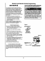
Receiver and Remote Control Programming
SI:,CURITY,I;
To _r_3" _ _
rtO_ _tmm_mt Qrm_at_m
ot _ m
_mdto¢
trzmsm_r are _
exceptforchemglng
li_e€ode=etUngor mpi_ng
thebatter/.THEREARENO OTHERUSERSERVICEABLEPARTS.
Your garage door opener receiver and remote
controlhave been pre-set at the factory.The door
will open when you press the LARGE remote
controlpush button. The code between the remote
controland the receiver changes with each use,
randomly accessing over 100 billionnew codes.
The 3-function remote controlcan also activate
additionalSECURITY+ garage door openers and/or
light controls.
Children operating or playing with a garage
door opener can Injure themselves or others.
The garage door could close and cause ser/ous
injury or death. Do not allow children to operate
the door push button(s) or remote control(s).
A moving garage door could Injure or kill
someone under It. Activate the opener only
when you can see the door clearly, it Is free of
obstructions, and Is properly adjusted.
Your SECURITY,I, opener willoperate with:
• several SECURITY+ remote controls(with blue
push buttons) utilizing up to 8 functions.
• one SECURITY+ Keyless Entry System
(Model 139.53684).
Follow the instructionsbelow to program your
opener to match any additionalremotes you may
purchase. See Accessories on page 38.
Figure I
To Add A Remote Control
If you have a Premium Control Console:
SeLecta remote €ont_ _
_on
to operate opermr
1. With the door closed, press and hold a remote
controlpush button. See Figure 1.
2. Press and hold the Light button on the door
control.
3. Press end hold the door controlpush button.
SECURITY'I"
3-Function
Remote Control
4. After the opener light flashes, release all buttons.
Test by pressing the remote push button.
If you do not have a Premium Control Console:
1. Press and holdthe selected remote control push
button.See Figure 1.
Figure 2
SECURITY÷
Garage Door Opener
2. Then press and release the SRT (learn) button on
the back panel of the opener, Figure 2. The
indicator light on the panel will begin to blink and
the opener light will flash once.
3. Release the remote push button.
Test by pressing the remote push button.
-_°
_
° ° ° °_'t
I
SRT(leam)
Button
Indicator
Ughl
BACK
PANEL
To Erase All Remote Control Codes
Press and hold the SRT button on the opener panel
until the indicator light turns off (about 6 seconds).
All remote controlcodes are now erased. Then
follow the steps above to re-program each remote
control.
N',
33
/Code
programming Instructlonl are
also located on the opener panel.
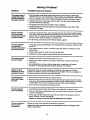
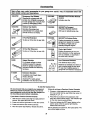
Having a Problem?
Situation
Probable Cause and Solution
The opener doesn't
operate from either
the Door Control or
the remote control:
1. Does the opener have electricpower?.Pluga lamp intothe outleLIf it doesn'tlight,
checkthe fuse box or the circuitbreaker.(Some outletsare controlledby a wall switch.)
2. Have you disabledall door locks?Review installationinstructionwarningson Page 11.
3. Is there a build-up of ice or snow under the door? The door may be frozen to the
ground. Remove any restriction.
4. The garage door spring may be broken.Have it replaced.
5. Repeated operation may have trippedthe overload protectorin the motor. Wait
15 minutes. Try again.
Opener operates
from the remote
control, but not from
the Door ControL"
1. Is the Door Control lit? If not, remove the bell wire from the opener terminal screws.
Short the red and white terminals by touchingboth terminals at the same time with a
piece of wire. If the opener runs, check for a faulty wire connectionat the Door
Control, a short under the staples,or a broken wire.
2. Are the wiring connections correct?Review Step 6, page 18.
The door operates
from the Door
Con#_l, but not from
the remote controL"
The remote control
has short range:
1,
Is any door push button flashing?If your model has the Lock feature, make sure the
lock is Off.
2. Your opener needs to re-leam a remote controlcode. Refer to Instructionson the
opener panel.
3. Program the receiver to match the remote controlcode.
4. Repeat the receiver programmingprocedurewith all remote controls.
1. Change the location of the remote controlin your car.
2. Check to be sure the antenna on the side or back panel of opener extends fully
downward.
3. Some installationsmay have shorter range due to a metal door,foil backed
insulation,or metal garage siding. (Antenna Extender Kit 41A3504)
Opener noise Is
disturbing In living
quarters of home:
If operational noise is a problem because of proximityof the opener to the living
quadere, the Vibration IsolatorKit 41A3263 can be installed. This kitwas designed to
minimize vibration to the house and is easy to install.
The garage door
opens and closes
by Itself."
1. Be sure that all remote controlpush buttonsare off.
2. Remove the bell wire from the Door Control terminals and operate from the remote
controlonly. If this solves the problem,the Door Control is faulty (replace), or there is
an intermittentshort on the wire between the Door Control and the opener.
3. Clear memory and reprogram all remote controls.
The door doesn "t
open completely:
1. Is something obstructingthe door?. Remove the obstructionor repair the door.
2. If the door has been workingproperlybut now doesn't open all the way, increase the
up force. See page 29.
3. If door opens at least 5 feet, the travel limits may need to be increased.One turn
equals 2 inches of travel. See page 28.
Repeat the safety reverse test after the adjustment Is complete.
The door stops but
doesn't close
completely:
Review the travel limitsadjustment procedureson page 28.
Repeat the safety reverse test after any adjustment of door arm length, close
force or down limit.
34
Having a Problem? (continued)
Situation
Probable Cause & Solution
The door opens but
won? close:
1. If the opener lights blink, check the safety reversingsensor. See page 23.
2. If the opener lights do not blink and it is a new installation,check the down force•
See AdjustmentStep 2, page 29• For an existing installation,see below.
Repeat the safety reverse test after the adjustment Is complete.
The door reverses for
no apparent reason
and opener lights
don't blink..
1. Is something obstructingthe door? Pull the red emergencyrelease handle. Operate
the door manually. If it is unbalanced or binding,call for professionalgarage door
service.
2. Clear any ice or snow from the garage floor area where the door closes.
3. Review the rome adjustment procedures on page 29.
4. If door reverses in the lullyclosedposition, decrease the travel limits(page 28).
Repeat safety reverse test after adjustments to force or travel limits. The need
for occasional adjustment of the force and limit Sefflngs Is normaL Weather
conditions in particular can affect door travel.
The door reverses for
no apparent reason
and opener lights
blink for 5 seconds
after reversing:
Check the safety reversingsensor. Remove any obstructionor align the receiving eye.
See page 23.
The opener light:
•.. doesn't turn on:
Replace the light bulbs (75 watts maximum). Use a standardneck garege door opener
bulb if regular bulb bums out.
•.. doesn't turn off."
Is the Light feature on? Turn it off.
The opener strains or
maximum force Is
needed to operate
door:
The door may be out ofbalance or the springsare broken.Close the door and use the
emergencyrelease to disconnectthe trolley.Open and closethe door manually.A property
balanceddoorwillstay in any pointof travelwhile being supportedentirelyby itssprings.If it
does not,disconnect the opener and call a professionalgaragedoor serviceman. Do not
increase the force to operate the opener.
The opener motor
hums briefly, then
won't work:
1. The garage door springsare broken. See above.
2. If the problemoccurson the first operationof the opener,doormay be locked. Disable
the doorlock.If the chainwas removedand reinstalled,the motormay be out of phase.
Remove thechain;cycle the motorto the downposition.Observe the drivesprocket.
When it turnsin e clockwisedirectionand stopsin the downposition,reinstallthe chain.
Repeat the safety reverse test after the adjustment Is complete•
The opener won't
operate due to
power failure:
1. Use the emergency release to disconnect the trolley.The door can be opened and dosed
manually. When the power is restored, press the Door Control push bar or button and
trolley will automatically reconnect (unless trolley is in lockout pos_on.) See page 32.
2. The Emergency Key Release accessory (for use on garages with no service door)
disconnects the trolley from outside the garage in case of power failure.
The chain droops
or sags:
It is normal for the chain to droop slightly in the closeddoor position.Use the
emergency release to disconnectthe trolley. If the chain returnsto normal height when
the trolley is disengaged and the door reverses on a one-inchboard, no adjustments
are needed (see page 11).
35
Repair Parts
Rail Assembly
Parts
f
3
KEY
NO.
1
2
3
4
5
6
7
8
7
Installation
t
2
3
41A4899
10A20
41A5032
4
5
6
7
8
9
10
11
12
13
14
15
29B137
41A2828
217A238
12B590
41A5047
178B35
31D431
10A2
31B430
175B34
12B350
41A5034
16
t2B584-1
41A5258
114A2400
DESCRIPTION
1A995
41C5141-1
183C158-3
Master link kit
Complete trolley assembly
Rail - front (header) section
183C157-3
144C56
41A5249
Rail - center/back section (2)
Chain Idler pulley
Chain and cable
144C62
12D598
Spreader (2)
U bracket
Parts
2
\
KEY PART
NO. NO.
PART
NO.
4
DESCRIPTION
Standard control console
3V 2032 Lithium battery
3-function remote control housing
(no circuit board)
Visor clip
Emergency rope & handle assy.
2-conductor bell wire - white & white!red
Header bracket w/clevis pin & fastener
Door bracket w/clevis pin & fastener
Curved door arm section
Keyless entry keypad cover
12 Volt battery
Keyless entry battery cover
Straight door arm section
Hanging brackets
Safety sensorkit (receivingand sending
eyes) with 3' 2-conductorbell wire attached
Safety sensor brackets (2)
NOT SHOWN
Assembly & Installationhardware bag (see
page 7).
Owner's manual
36
10
110-
12:.
1315
16
14
Repair Parts
Opener Assembly
Parts
(oo_)
uMrrswrrc.
erc_w_ Contact
ASSEMBLY !
Drive
.n
Gea
Center Limit
Contact
KEY
NO.
PART
NO.
1
2
310380
41C4220A
14
(Up)
_tact
_
_'
i.,,.___
Wire
Ye tow
Wire
DESCRIPTION
3
41A2817
4
5
6
7
41 B4245
41A4352
175B88
108D48-2
Sprocket cover
Gear and sprocket assembly
Complete with:
Spdng washer
Thrust washer
Retaining ring
Seadng plate
Roll pins (2)
Or_vegear a_d worm gear
Helical gear w/retainer and grease
Drive/worm geer kitw/grease
Roll pins (2)
Line cord
End panel
Lightsocket
Lens
8
9
10
30E363
12A373
41A3150
Capacitor - 1/2HP
Capacitor bracket
Terminal block w/screws
KEY
NO.
PART
NO.
11
41D3058
12
13
14
15
16
17
18
19
4100328-4
41A2818
41D3452
41 C4398A
41C4246
41A2826
41A2822A
41A5021-3E
2O
41A3691
41A2825
37
DESCRIPTION
Universal replacement motor &
bracket assembly
Complete with: Motor, worm,
bracket, beadng assembly,
RPM sensor
Cover
Helical gear & retainer w/grease
Limit switchassembly
RPM sensorassembly
Wire harnessassembly w/plug
Shaft bearing kit
Interruptercup assembly
Receiver logic beard assembly
Complete with:
Logicboard, End panel w/all labets
End panel
NOT SHOWN
Opener assemblyhardware kit
(includesscrews not designated by
a numberin _lustration).
Accessories
Sears offers many useful accessories for your garage door opener. They are Illustrated below with
Sears model numbers and dsecrlptlons.
139.53702
139.53681
i Emergency Key Release:
Requiredfor a garage with NO
access door. Enables homeowner
to open garage door manually from
outside by disengagingtrolley.
139.53703
Includesvisor clip.
Outdoor Key Switch:
139.53680
Operates the garage door
automatically from outside when
remote control is not handy.
53724
8 Foot Rail Extension
139.53684
SECURITY+ Keyless Entry:
Enables homeowner to operate
garage door opener from outside
by entering a 4 digit code on
speciallydesigned keypad.
10 Foot Rail Extension:
139.53686
Plug-InLight Control:
Enables homeowner to turn on a
lamp, televisionor other appliance
from car, bedside, or anywhere in
the home with a remote.
139.53709
Door Clearance Brackets:
To allow a 10 foot door to open fully.
Support Brackets:
For finished ceilingsor where
additional support is required,
based on garage construction.
Includes brackets and fastening
hardware.
41A5281
SECURITY+ Compact
3-Function Remote Control:
With loop for attaching key ring.
To allow an 8 foot doorto open fully.
53589
SECURITY+ 3-Functlon Remote
Control:
( For Sectional Doors On/y)
Replacestop brackets and rollerson
doorto reduceheightof door travel
For use when installingopener in
garagewith low headroomclearance.
Extension Brackets:
(Available only through Sears
Parts & Service)
(Optional) For safety sensor
installationonto the wall or floor.
To Add the Keyless Entry
We recommend that you program your password
before you install the Keyless Entry. You will not
need assistance, and you can test the reception at
the mounting location before installation.
If you do not have a Premium Control Console:
ff you have a Premium Control Console:
2. Press the four buttons for the password, then
press and holdthe Enter button. The indicator light
on the door opener panel will blink.
1. Choose a 4-digit password using numbers from
0 to 9 (a number can be used more than once, for
example, 4, 0, 4, 1).
1. Withthe doorc/osed, press the four digit password
desired, then press and hold Enter.
3. Press and release the SRT (learn) button on the
opener panel. After the opener light flashes,
release the Enter button.
2. Press and hold the light button on the door control.
3. Press and hold the door controlpush bar.
4. After the opener light flashes, release all buttons.
Test by pressingthe password, then press Enter. The
door shouldbegin to move.
38
Index
Access Door/Outslde Key Release Accessory ........................................................ :. ..................................... 4, 5
Chain Tension ..............................................................................................................................................
4, 5, 11
Electrical Safety Warnings ........................................................................................................................
2, 20, 31
Garage Door
Testing for balance, bindingand sticking................................................................................................... 3, 28, 31
Determining high point of travel:
Sectional door...................................................................................................................................................
12
One-piece door.................................................................................................................................................
13
Disabling existing locks....................................................................................................................................
3, 11
Door clearance brackets (for garages with low headroom)........................................................................... 12, 38
Force controls
Adjustment procedures.................................................................................................................................
4, 29
Problems that might requireforce adjustments ................................................................ . ......................... 34, 35
Safety warnings ..........................................................................................................................................
29, 31
Door hardware .....................................................................................................................
3, 9, 11, 12, 18, 31, 32
Maintenance instructionlabel ........................................................................................................................
11, 28
Reinforcement requirements ...........................................................................................................................
4, 24
Removing of all ropes.......................................................................................................................................
3, 11
Possible door damage ...................................................................................................................................
16, 24
Travel limits
Adjustment procedures.....................................................................................................................................
28
Problems that mightrequire limitadjustments............................................................................................ 34, 35
Safety warnings ..........................................................................................................................................
28, 31
Manuel (Emergency) Release Rope & Handle
Lockout feature ....................................................................................................................................................
32
Manual disconnect...............................................................................................................................................
32
Safety warnings .................................................................................................................................
11, 19, 31, 32
Opener Terminals
Door controlconnections.....................................................................................................................................
Safety reversingsensor connections...................................................................................................................
18
23
Operational Noise
Sprocket noise.....................................................................................................................................................
Vibration noise (isolatorkit) .................................................................................................................................
11
34
Receiver and Remote Control
Programming the receiver ...................................................................................................................................
Erasing all codes .................................................................................................................................................
Activating other openers ......................................................................................................................................
Safety warning .....................................................................................................................................................
Problems with remote controloperation ..............................................................................................................
33
33
33
33
34
Safety Reverse Test Procedure ..........................................................................................................................
30
Testing required.................................................................................................................................
11, 30, 34, 35
Safety reverse system problems
Securing header bracket to wall .......................................................................................................................
12
Adjustingtravel limits........................................................................................................................................
28
Applyingexcessive force on the door...............................................................................................................
29
Buckling or uneven floor.................................................................................................................................
4, 5
Safety Warnings ......................................................... 2, 3, 9, 11, 12, 16, 18, 19, 20, 21, 24, 28, 29, 30, 31,32, 33
User Instruction Label for garage wall ........................................................................................................
39
11, 18
For In-home major brand repair service:
Call 24 hours a day, 7 days a week
1-800-4-MY-HOME"
Para pedir eervlcio
de reparaci6n
(1-800-469-4663)
a domicilio-
For the repair or replacement
1-800-676-5811
parts you need:
Call 6 a.m. - 11 p.rn. CST, 7 days a week
PartsDirect
1-800-366-PART
(1-800-366-7278)
www.sears.com/partsdirect
Para ordenar piezas con entrega a domicilio - 1-800-659-7084
For the location of a Sears Service Center in your area:
Call 24 hours a day, 7 days a week
1-8OO-488-1222
To purchase or inquire about a Sears Maintenance Agreement:
Call 7 a.m. - 5 p.m. CST, Monday - Saturday
1-800-827-6655
IHSEARS
omeCentralSj
SEARS WARRANTY
FULL 90-DAY WARRANTY ON GARAGE DOOR OPENER
For 90 days from the date of purchase, Sears will repair this Garage Door Opener, free of charge, if defective in material or
workmanship.
LIMITED WARRANTY
From the 91 st day until one year from the date of purchase, Sears will furnish replacement parts forany defective parts, free of
charge. You pay for labor.
LIMITED WARRANTY ON MOTOR
1/2HP MOTOR: After 1 year and through5 years, it the motor on this Garage Door Opener is defective, Sears will furnish a
replacement motor, free of charge. You pay for labor.
LIMITATION ON LIABILITY
SEARS WILL NOT BE LIABLE FOR LOSS OR DAMAGE TO PROPERTY OR ANY INCIDENTAL OR CONSEQUENTIAL LOSS
OR EXPENSE FROM PROPERTY DAMAGE DUE DIRECTLY OR INDIRECTLY FROM THE USE OF THIS PRODUCT. Some
states do not allow the exclusion or limitation of incidental or consequential damages, so the above limitation or exclusion may not
apply to you.
This warranty does not cover light bulbs or repair parts necessary because of operator abuse or negligence, includingthe failure to
install, adjust and operate this garage door opener according to instructionscontained in the owner's manual.
WARRANTY SERVICE IS AVAILABLE BY SIMPLY CONTACTING THE NEAREST SEARS CENTER/DEPARTMENT IN THE
UNITED STATES.
This wan'anty applies only while this product is in use in the United States.
This warranty gives you specific legal rights, and you may also have other rights which vary from state to state.
Sears, Roebuck and Co., Dept. 817WA, Hoffman Estates, IL 60179
114A2400
©1999, All Rights Reserved
Printed in Mexico