1
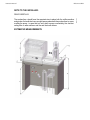
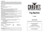
REN/PLUS
Versión: 3.0
Instruction manual
More information go to www.rilo.com.ar/products
Welcome to RILO
Instruction manual
NOTE TO THE INSTALLER:
READ CAREFULLY.
ENG
The worksurface should have the apropiate size to place both the coffee machine
and grinder. It should also have enough space underneath the worksurface to acommodate the pump – in case that is is not a built-in pump- comfortably, the dechlorinating filter or water softener and the and the knock boxes.
ESTIMATIVE MEASUREMENTS
1
1
Welcome to RILO
Instruction manual
B: MACHINE DEPTH: 510mm (51cm)
C: MACHINE HEIGHT: 480mm (48cm)
D: ROOM FOR GRINDER: 300mm (30cm)
E: MAXIMUM HEIGHT OF THE WORKSPACE: 950mm (95cm)
F: MINIMUM HEIGHT OF THE WORKSPACE: 850mm (85cm)
REN PLUS MACHINE
A: MACHINE WIDTH :
2 gr. 670mm (67cm)
3 gr. 810mm (81cm)
B: MACHINE DEPTH: 570mm (57cm)
C: MACHINE HEIGHT: 550mm (55cm)
D: ROOM FOR GRINDER: 300mm (30cm)
E: MAXIMUM HEIGHT OF THE WORKSPACE: 1000mm (100cm)
F: MINIMUM HEIGHT OF THE WORKSPACE: 950mm (85cm)
2
Welcome to RILO
ENG
Instruction manual
INSTALLATION
A. WATER DRAINING
A lead or plastic pipe of 1½” at least, should be attached to a ½” hose coming from
the drain box of the machine.
B. WATER SUPPLY
It Should end with a water valve with a screw top or a thread of ½”.If the machine has
a built-in pump connect to the valve an 8 mm rubber hose.In case the engine should
be separated, connect the hose to the pump entry.
ATTENTION: In every case you should let run plenty of water, before you start operating the machine in order to dispose the pipes from any residue that could have
been left during the contruction.
3
Instruction manual
Welcome to RILO
C. GAS SUPPLY
It should be of a galvanized iron pipe, finished with a valve with a screw top or thread
of ½”. The connection from the gas main valve to the machine gas valve has to be
done with a 5/16” copper pipe and a female ¼” coupling.
ATTENTION: In every case you should let run plenty of water, before you start operating the machine in order to dispose the pipes from any residue that could have
been left during the contruction.
D. ELECTRIC ENERGY (UNDER-COUNTER CABINET)
All machine and coffee grinder components fuction at 220V C.A. 50/60Hz with ground
connection. (110 V C.A. only upon request) Install a 4 plug electrical outlet of 10A
for the coffee machine if it is gas heated. If the heating is dual or electric it should
be 20A
E. ELECTRIC ENERGY (OVER-COUNTER CABINET)
Take notice to use a 10º ground connectionfor the grinder.
F. WATER PURIFIER
It should have enough space under the counter (see section for its mainteinance)
G. KNOCK BOX
It should have enough space under the counter
H. DRAINING BOX
The ½” hose coming from the draining pipe should be inserted into the draining box
(A).
I. DRILLING OF THE COUNTER (WORK SPACE)
Present the coffee machine on the counter top and make a 80 mm diammeter perforation placed 500mm from the left side and 150mm from the front of the baseboard
of the machine.
IMPORTANT
It might happen unexpectedly or for any reason, that your water supply service is interrupted, what would affect the normal functioning of your RILO coffee machine.
In order to avoid that certain components suffer serious damages, your RILO machine has been equiped with the innovative BA-3 system.
4
Instruction manual
Welcome to RILO
This system was programed to cutt off the filling process at 90 seconds. Hence, the
technician who makes the installation, while doing the first load has to take into account , that he should turn on and off the coffee machine as many times as the boiler
reaches its proper level.
NOTE: Take notice that the size of the boilers vary with each different model. This
means that the filling process of bigger models might requier that the turning on and
off it’s done many more times.
RECOMENDATIONS FOR THE INSTALLATION TECHNICIAN
WATER:
If possible connect the machine to a water supply with 1 bar/cm2 pressure, with ½”
water pipes and a lock water valve which is very important to check ii is in the “opne”
position.
DRAINAGE:
The fall of water it’s because of the level differences, therefore, it’ shouldn’t exist undulations in the way of the drainage hose to the free fall.
5
ENG
The BA-3 it’s an alarm system and cut-off time control, which interrupts the the fuctioning of the pump and emits a sound signal when there is a lack of the water supply/
mains.
Welcome to RILO
Instruction manual
GET TO KNOW YOUR RILO COFFEE MACHINE
1. Coffee groups.
2. Coffee filter-holders
3. Boiler manomenter
4. Electropump manometer
5. Hot water tap
6. Steam wand
7. Group switch
8. Red light boiler resistance (**)
9. On/off Switch
10. Gas knob (*)
11. Switch on button(*)
12. Level tube indicator
OFF
ONN
RESISTANCE
(*): Only in gas and dual machines
(**): Only in electric and dual machines
6
Instruction manual
Welcome to RILO
Verify that the water leve is always on the middle of the glass tube(12).
Before start the daily operation of the machine, let hot water run through the groups
(1) with the filter holders (2) on to promote the warming of the set and the rinsing of
them.
Verify that the grinding it’s just right and that the amount of ground coffee is the correct one. One stroke for the simple coffee filter and two for the double.
If you don’t operate or use the machine for more tan 10 (ten) minutes, when you resume the operation let run some water through the groups (2).
GENERAL CONSIDERATIONS FOR THE MANTEINANCE OF THE RILO COFFEE MACHINE.
Check the cleansing of the groups’ showers.
Checkthe cleansing of the filterholders and the coffee filters.
Check the cleansing of the boilers due to the inlay produced by the scale/fur/tartar.
For every machine that’s being permanently in use, is advisable that a specialized
technician makes a check up to evulate the possible manteinance tasks.
7
ENG
SPECIAL CARE AT THE BEGINING OF THE OPERATION
Welcome to RILO
Instruction manual
INSTRUCTIONS FOR THE TECHNICIAN
ON THE GAS REGULATION
+ TEMPERA-
- PILOT
+ PI LOT
- TEMPERATURE
8
Welcome to RILO
Instruction manual
MAXIMUM TEMPERATURE CALIBRATION.
ENG
1. Cut off the electricity between the coffee machine and the main electricity supply.
2. Remove the lid of the pressure switch pulling from the superior edge of the lid.
3. Connect again the machine to the main electricity supply. At this point and after
some time the machine will start raising steam pressure in the boiler until it stops.
4. Two options might come up:
Option 1
If the cut were produced before the desired pressure, do the following: Cut the electricity supply and with a ½” box wrench, turn the nut to the right (clockwise), no more
than one turn at a time.
Connect again the machine to the main electricity supply and if you achieve to reach the desirable pressure rise, cut again the electic supply and loosen the nut but
this time to the left (anti-clockwise) until you notice that the contacts triggers themselves, which means that the operation is complete.
Option 2
If after some time the machine started to raise steam and it supassed the desired
pressure by you with the regulation that comes from manufacturing, the main electric supply must be cut off, let it cool down and when the steam pressure is going
down a trhough the desired pressure, take a ½” box wrench and turn the nut anticlockwise softly until you fell the contacts trigger themselves, this means the operation is complete.
NUT 1/2” NUT 5/16”
9
Welcome to RILO
Instruction manual
Important: The pressure switches are delivered already calibrated, nevertheless, if
you want to regultae it yourself, please follow the previous steps.
CALIBRATION OF THE DIFFERENTIAL OF THE SYSTEMS OF MAXIMUM
IGNITION (disconnection) AND MINIMUM (re-connection) .
To modify the differential pressure handle the 5/16” nut. Turning to the right the difference increases (greater fall of preassure before the re-connection). This settles ,
with a slot, over a pair of cogs on the arm of the valve. When it turns, you will notice
everytime it falls into that position (1/2 turn).
Re-connnect electrically so the pressure switchs makes the disconnection and reconection, while observing the indication in the manometer. If it is necessaryrepeat
the previous steps.
There, as well, are two different positions for the support of the nut,”A” and “B” without having to handle the 5/16” nut.
To pass the nut from one possition to the other (“A” or “B”),you just have to scroll it
inside the slot. As it is hold by the spring, it will make a click going from one support
to the other.
With the nut supported on the “A” cogs the result obtained will be from medium to
maximum. To reach the mínimum differential value you should pass to point “B” (this
is the appropiate point for our coffee machine.
Take note: It is necessary that the differecial pressure it’s kept at its highest level posible, to ensure a greater support strength between that contacts.
POSITION A
POSITION B
A lower support strength produces an excesive splutter/sparkling in the contacts,
specially when the electric charge is high.
Before leaving the preassure switch working, please check that that electric connections are firmly tighten and the nut that regulates the differential system are well
fit over the cogs, so it won’t move because of vibrations.
10
Welcome to RILO
Instruction manual
From the electric point of view the pressure switch it’s a tri-polar interruptor –which
uses only 2 poles- that allows the controlling of the connection and disconnection of
the resistance that heats the boiler.
To replace a faulty pressure switch follow these next steps:
Cutt off the electric supply from the machine. Remove the lid pulling from the superior edge. Unplug the wires removing the screws from electrical connection sockets
of the pressure switch
Make sure the pressure of the boiler it’s in zero. If it is not in zero open the steam
valve to ensure the total decompression of the boiler.Disconnect the the entry of
pressure from the lower part of the pressuere switch.
Remove it from the support and replace it for an original spare part.
Re connect the pressure entry and the cables as it’s shown in the next scheme:
NEUTRAL PHASE
11
ENG
DESCRIPTION OF THE ELECTRIC CONNECTIONS
Instruction manual
Welcome to RILO
To take note: The central pole of the pressure switch it’s not connected. If the fault is
verified in one of the two poles in use, you have the possibility to change the positions of the wires from the faulty pole connecting them to the central pole.
IMPORTANT: DO NOT BYPASS OR TRY TO JUMPER NEITHER OF THE POLES OF THE
PRESSURE SWITCH IN ORDER NOT TO COMPROMISE THE ELECTRIC SAFETYOF THE
MACHINE.
12
Concordia 1178/86 (C1487DIX)
Cuidad Autonoma de Buenos Aires
Tel. (54 11) 46710852 (rotativas) Fax. (5411) 4636 1072
e-mail: [email protected]
www.rilo.com.ar