1
Serial
Number
Modelandserial
numbermaybefound
underbelt guard.
Youshouldrecordboth
modelandserialnumber
in asafeplacefor
futureuse.
_
12-iNCH
WOOD-TURNING
CAUTION:
Read
GENERAL
ADDITIONAL
SAFETY
o assembly
®operating
• repair parts
carefully
Part No. 70017
LA THE
and
INSTRUCTIONS
Sold
CRRFTSMRN
by
SEARS,
ROEBUCK
AND
CO.,
Chicago,
IL.
60684
UoS.A.
Printed
h'_ U.SA.
CRAFTSMAN
WOOD TURNING
LATHE
]
i
f within one year from
material or workmanship,
Warranty
service
United States.
the date of purchase, th s Craftsman
SearsWill repair it,free of charge,
is available
by simply
contacting
the
nearest
Wood
Turning
Lathe fa Is due
Sears store or Service
to a defect
Center throughout
in
]
the
This warranty gives you specific legal rights, an(] you may also have other rights which vary from state to
state.
SEARS, ROEBUCK AND CO.
BSC 41-3
SEARS TOWER
CHICAGO, IL, 60684
GENERAL
1. KNOW
YOUR
SAFETY
POWER
INSTRUCTIONS
TOOL
use
Read the owner's manual careful V. Learn tsapphcatlon
and lim=tations
as well as the specifc
potential
hazards
ALL TOOLS
n worKing
and in proper
ADJUSTING
adj Jstment
17. AVOID
Make
in.
visitors should
= Wlttl
ENVIRONMENT
be kept a safe distance
padlocks,
The use of
switches,
from WOrK area
or bv removing
10. USE RIGHT
better
and
safer
or attachment
Dart That
replaced
_t was not
periods
of operation.
changing
oe_formchanging
accessories
such
as
STARTING
7 "OFF"
oosition
before
mugging
ACCESSORIES
improper
accessor=es may cause hazards.
is tipped
or if the
matenals
above or near me tOOl such mat
to stand on the tool to reach them.
PARTS
_s damageo
should
be
orooerly
Turn
power
off.
complete
stop.
(Head Protection)
2
reoalreG
or
the dl_ection
of
OF FEED
22. NEVER LEAVE TOOL
UNATTENDED
Wear safety
goggles
(must
comply
with
ANS Z87.1)
at all times. Also, use face or dust mask if cutting oper
ation is dusty, and ear protectors
(plugs or muffs) durin_
extended
CARE
Feed work into a blade or cutter against
rotation
of the blade or cutter omv_
Do not wear loose clothir_J, gloves, neckties or jewelry
(rings,
wristwatches)
to get caught
m moving
carts.
NONSLIP
footwear
is recommended.
Wear proteetwe
hair covering
to contain
long hair
Roll
long sleeves
above the elbow.
GOGGLES
t_mes
STAND ON TOOL
21. DIRECTION
11. WEAR PROPER APPAREL
12. USE SAFETY
Jt's
[c ooe_dte
Before further
use of the tool. a guaro or other cart mat
s damaged should be carefully
checked to ensure that it
will ooerate properly
and perform
_ts ntendep
function.
Check for ahgnment
of moving parts, Oinolng of moving
parts, breakage
of parts, mounting,
ano any otner conditions
that may affect
ts ooerat_on.
,_ guata or other
at the rate for which
1o eo a job
s
20. CHECK DAMAGED
starter
TOOL
Don't
force tool
designed for.
switch
Do not store
t is necessary
9. DON'T FORCE TOOL
job
at a
Serious injury COUlO occur if tne too[
cutting tool is accidentally
contacted.
keys.
It wdl do the
it was designed
o_actical
llanos
the owner's manure for recommended
accessories.
toe nstruct=ons
that accomoanv
the accessories.
19. NEVER
KID-PROOF
master
wneP,
TOOLS
ACCIDENTAL
sure
Consult
Follow
AWAY
8. MAKE WORKSHOP
.vof_
t_ees _om
ano balance
18. USE RECOMMENDED
Floor
Don t use power tools in damp or wet locations or expose them to rain. Keep work area well lighted_ Provide
adequate surrounding
work sp_ce.
All
_o_o
before
serv;cmg;
when
blades, o_ts. cutters, etc.
KEYS AND WRENCHES
Cluttered
areas and benches
=nvlte accidents
must not be shppery due to wax or sawdust.
7, KEEP CHILDREN
[o
nan_q
TOOLS WITH
16. DISCONNECT
and align.
5. KEEP WO RK AREA CLEAN
DANGEROUS
vise
your
Keen tools shard ano c_ean for nest and safest
ante.
Follow
mstructlo[ls
for lubricating
ano
accessories.
Form
habit of checkmg
to see mat keys and aejustmg
wrenches are removed from tool before turning it on.
6. AVOID
a
footing
15. MAINTAIN
ment.
4. REMOVE
or
using
Keepp_oper
IN PLACE
oroer,
TOOLS
14. DON'T OVERREACH
This tool is equipped
with an approved
3-conductor
cord and a 3-prong grounpm3
type plug to fit the prooer
grounding
type receptacle.
The green conductor
in the
cord is the grounding
wire. Never connect tne green wire
to a live terminal.
3. KEEP GUARDS
clamp5
safer than
too
pecul=ar to this tool.
2, GROUND
FOR POWER
13. SECURE WORK
Don't
RUNNING
leave
tOOl
until
!t comes
to
._
Safety is a Combination of operator common sense and
alertness at all times when the Lathe is being used.
h. Remove all loose knots before installing workpiece between centers or on the face plate.
WARNING:
FOR YOUR OWN SAFETY, DO
NOT ATTEMPT TO OPERATE YOUR LATHE
UNTIL IT IS COMPLETELY
ASSEMBLED AND
INSTALLED
ACCORDING
TO THE INSTRUCTIONS . .. AND UNTIL YOU HAVE READ
AND UNDERSTAND
THE FOLLOWING:
i.
Never leave the Lathe work area with the power
on before the Lathe has come to a complete stop,
or without
removing and storing
the switch key.
j.
Never operate the Lathe with protective
the unused
shaft
end of the motor
7.
PAGE
1. General Safety Instructions
for Power Tools . .
2
2. Getting to Know Your Lathe ............
13
3. Basic Lathe Operation .................
15
4. Maintenance .......................
19
5. The Lathe and motor must be bolted down to a stand
or workbench for stability.
6. Protection:
a,
b,
C.
Hang your turning
tools on the wall toward the tailstock end of the Lathe. Do not lay them on the bench
so that you must reach over the revolving workpiece
to select them,
8,
Keep firm hold and control of the turning
tool at all
times. Special caution must be exercised when knots
or voids are exposed to the turning
tool.
9,
Note the following
the front of the
DANGER
belt _J_rd.
e.
which
appears
on
DANGER
Wear safety gogglesthat comply with ANS Z87.1t968, and a face shield if operation is dusty.
Wear ear plugs or muffs during extended periods
of operation.
FOR
When turning between centers or on the face plate,
always rough-out "out of round" workpieces at
slow speed. Running the Lathe too fast, so that it
vibrates, could cause the workpiece to be thrown
from the Lathe . . . or the turning tool to be
jerked from your hands.
Always revolve the workplace by hand before
turning on the motor, tf the workplece strikes the
tool rest, it could split and be thrown out of the
Lathe.
Do not allow the turning tool to "bite" into the
workpiece which could result in splitting of the
workpiece or the workpiece being thrown from
the Lathe. Always position the tool rest above the
centedine of the Lathe for spindle turning, Do not
apply the turning tool to the workpiece below the
level of the tool rest.
YOUR
OWN
REAO
AND
UNDERSTAND
OWNER'S
ft'ANUAL
BEFORE
ATING
THIS MACHINE
2
%15AR FACE SHIELD
TY GOGGLES
3
DO
NOT
WEAR
GLOVES
TIES OR LOOSE CLOTHING
4
BE
POSIT}VE
TIGHT
BEFORE
HINE
5
TURN
WORKPIECE
BY HAND
BE
FORE
APPLYING
POWER
TO DE
TERMINE
IT CLEARS
THE
TOOL
REST OR OTNERMACHIN£
PARTS
6
ROUGH
OUT
FACEPLATE
WORK
PIECES
BEFORE
INSTALLING
ON
FACEPLATETOAVOIDEXCESSIVE
Before
attaching
a workpiece
to
always "rough
it out" to as "true
sible. This will minimize
vibration
fasten
the
Failure to perform
cause the workpiece
workpiece
to the
Think
11,
Complete
TO
AND
A
OR SAF E
ALL
LOCKS
OPERATING
AND
"_HE
O_ER
NECK
ARE
,MAC
POSSIBLE
IN
LOWESTSPEEDWHEN
NEW
WORKPIECE,
OR
BETWEEN
CEN
M_Ntt2_ZE
POTENTIAL
Safety
hand
sending
of
between-centers
or face
plate mounted
workpieces
BEFORE
removing
from
the lathe, NEVER
attempt
to remount
a face plate
turning
to the face plate for any reason. NEVER
attempt
to remount
a between-centers
turning
if the
original
centers in the turning
have been a{tered or
removed,
Be Positive
the lathe is set at the lowest
the face plate
round"
as poswhile turning.
securely
ALWAYSUSE
STARTING
FACEPLA_'E
TERS.
INJURY
10.
SAFETY:
I
7
Do not run the Lathe in the wrong direction, This
could cause the turning tool to be thrown from
your hands. The Lathe must run in a direction so
that the workpiece turns toward you.
Always
plate,
label
Eyes, Hands, Face, Ears, Body
VIBRATION
JURY
d.
cover on
removed,
speed if remounting
non-altered
original
face
a between-centers
centers.
turning
with
12. Use extra
caution
in mounting
a between-centers
turning
to the faceplate
or a faceplate
turning
to between-centers
for subsequent
operations.
BE POSITIVE the lathe is set at the lowest speed before turning ON.
these set-up operations
could
to be thrown
from the Lathe.
g. Avoid awkward hand positions, where a sudden
slip could cause a hand to move into the workpiece.
13. NEVER
attempt
to turn on the facep!ate or be._,_een centers
a workpiece
which
contains
any cracks or
loose knots,
3
addlhonai
•
•
safety mstruchons
•
•
lathes
WARNING:
THE FOUR STEP LATHE
AND
MOTOR
PULLEYS
FURNISHED
ARE DESIGNED TO RUN THE LATHE AT THE CORRECT SPEEDS WHEN USED WITH A 1725
R.P.M. MOTOR. DO NOT USE A 3450 R.P.M.
MOTOR TO INCREASE THE SPEED BECAUSE
IT COULD BE DANGEROUS.
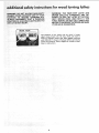
WARNING:
DO NOT ALLOW FAMILIARITY
(GAINED FROM FREQUENT
USE OF YOUR
MACHINE)
TO BECOME COMMONPLACE.
ALWAYS
REMEMBER
THAT A CARELESS
FRACTION OF A SECOND IS SUFFICIENT
TO
INFLICT SEVER INJURY.
gVEAR
for wood turning
YOUR
The operation
of anv power tool can result in foreign
objects being thrown
into the eves, which can result in
severe eve damage. Always wear safety goggles complying
with ANSI Z87.1
(shown on Package) before commencing
power too_ operation.
Safetv
retail or catalog stores,
4
Goggles are available
at Sears
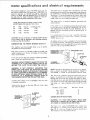
This power tool is equipped
with a 3*conductor
cord and
grounding
type plug which has a grounding
prong, approved
by Underwriters'
Laboratories
and the Canadian*Standards
Association.
"Tile ground conductor
has a green jacket and
is attached to the tool housing at one end and to the ground
prong in the _ttachment
plug at the other end.
This Lathe is designed to use a 1725 RPM motor only. Do
not use any motor that runs faster than 1725 RPM, It is
wired for operation on 110-120 volts, 60 Hz., alternating
current. IT MUST NOT BE CONVERTED TO OPERATE
ON 230 VOLTS. EVEN THOUGH SOME OF THE RECOMMENDED MOTORSARE
DUAL VOLTAGE.
This plug requires
outlet as shown.
THESE MOTORS HAVE BEEN FOUND TO RE
ACCEPTABLE FOR USE ON THIS TOOL,
HP
1/3
RPM
1725
VOLTS
110-120
CATALOG
1250
1/2
1725
110-120
1254
1/2
1725
110-120
1255
CAUTION:
Do not use blower or washing machine motors
or any motor with an automatic
reset overload protector
as their use may be hazardous.
TO POWER SOURCE
This machine
must be grounded
the operator
from electric shock.
while
If VOU are not
have it check
usre that
your
by a qualified
outlet
THREE
pro_g
MAKE SURE
CONNECTED
If power cord is worn or cut,
it replaced immediately.
2-PRONG
RECEPTACLE
ADAPTER
or damaged
less than
in any way, have
150 volts
.........."-_
The use of any extension
cord will cause some loss of
power.
To keep this to a minimum
and to prevent
overheating and motor burn-out,
use the table below to determine the minimum
wire size (A.W.G,)
extension
cord. Use
only 3 wire extet/sion
cords which have 3-prong grounding
type plugs aqd 3-pole
receptacles which
accept the tools
plug.
it has a plug
Cord
/
Length
Wire
Size
100 Ft.
A.W.G.
16
100-200
Ft.
14
200-400
Ft,
10
CHECK MOTOR
/n ui
/_
ii/',,
LUG
NOTE: The ada!._ter illustrated
is for use only if you already
have a properly
grounded
2-prong receptacle.
Adapter
is
not allowed
ir_ Canada by the Canadian
Electrical
Code.
3--PRONG
PLUG
OUTLET.,,,,...!
GROUNDING
grounded,
Upto
\
electrician
grounded
o,_iet,
"flits
tS
TO A
I
Extension
J
I
you have a qualified
outlet
with a proper!y
electrician.
WARNING:
IF NOT PROPERLY
GROUNDED
THIS
POWER TOOL CAN INCUR THE POTENTIAL HAZARD
OF ELECTRICAL SHOCK. PARTICULARLY
WHEN USED
IN DAMP LOCATIONS IN PROXIMITY TO PLUMBING.
IF AN ELECTRICAL
SHOCK OCCURS THERE IS THE
POTENTIAL
OF A SECONDARY HAZARD SUCH AS
YOUR HANDS CONTACTING THE CUTTING TOOL.
PROPERLY
GROUNDED
that
ploI_g
KNOWNGROlJ_!_
WARNING: DO NOT PERMIT FINGERSTO TOUCH THE
TERMINALS
OF PLUGS WHEN INSTALLING
OR REMOVING
THE PLUG TO OR FROM THE OUTLET.
If your unit is for use on
that looks like below.
type
protect
grounded type
or Circuit-Saver
is properly
grounded
An adapter as shown below is available for connecting
plugs
to 2-prong receptacles.
The green grounding
lug extending
from the adapter must be connected
to a permanent
ground
such as to a properly
grounded outlet box.
OUTLET
in use to
Plug power cord into a 110-120V
properly
outlet
protected
by a 15-amp. time delay
fuse or circuit
breaker.
3-conductor
If the outlet you are planning to use for this power tool is
of the two prong b/pe DO NOT REMOVE OR ALTER
THE GROUNDING
PRONG IN ANY MANNER. Use an
adapter as shown and always connect the grounding lug to
known ground.
NO.
It is recommended
replace the TWO
CONNECTING
a mating
ROTATION
WARNING:
FOR YOUR
OWN SAFETY,
MAKE
PLUG IS NOT CONNECTED
TO POWER SOURCE
LET. WHEN CHANGING
MOTOR
ROTATION.
UJ I GROUNDING
PRONG
The
motor
must
rotate
the shaft enC o which
page 12}. If b does not,
the instructions
furnished
5
CLOCKWISE
when
viewed
SURE
OUT-
from
you wilt mount
the pulley.
(See
change the direction
according
to
with the motor.
ontents
...................
Check motor rotation ................
GETTING TO KNOW YOUR WOOD
LATHE
.........
Belt guard lock ..................................
13
Index pin
13
.....................................
Spindle lock hole
Tool rest lock .." ..............
...,.,
................
. ............
13
Spur center and cup center (aligning centers) ...........
14
Tailstock ....................................
14
Speed chart ....................................
BASIC LATHE OPERATIOIk
........................
12
13
13
13
15
Spindle turning
16
18
19
LUBRICATIOI_
19
...................................
RECOMMENDED
Handwheel .....................................
13
REPAIR
Tailstock ram lock ...............................
13
7/16-inch
wrench
Framing
PARTS
....................
..................................
21
22
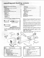
If any parts are missing, ao not attempt
to assemDle th_
lathe plug in zne power cord or turn the switcn on until tn(
mtssing
oarta are obtained
and are nstalled
correctly
(medium)
Using a 7 16" wrench, remove the wood blocks attached to
the Lathe. Save the nuts. bolts and washers, you will need
for attaching the Lathe to the bench.
square
Remove the
any ordinary
Your lethe is shipped complete
motor, or bench). The V-Belt
"furnished.
ACCESSORIES
Separate
all parts from packing
materials
and check each
one with
the "Table
ol Loose Parts" to make certain
all
_tems are accounted
for,
before discarding any packin£
material,
wrench
Screwdriver
...............................
Indexing ......................................
MAINTENANCE
.................................
13
3/8-inch
15
15
Changing speeds .................................
Tool rest base lock ...............................
TOOLS NEEDED ='-'=`-'=.'."'.".'-
13
On - off switch ..................................
in one carton [without
and motor pulley are
protective
oil that is applied to the
household
type
grease anc spot
bed. Usa
remover,
CAUTION:
Never use gasoline, naptha or similar
highly volatile solvents,
Apply a coat of automobile wax to the bed. Wipe all parts
thoroughly with a clean dry cloth.
3
Key
No.
3
4
5
6
Table of Loose Parts
Motor Pulley ......................
Belt, 'Vee 1/2x37 .................
Wood Turning Lathe .................
Owner a Manual ....................
Belt Guard Assembly ................
PlasticBag, Part No. 70018-Containing
Wrench, He×
Hex 3/16
5/32. ................
Screw, Type 23 Pan 10-32 x 3/8 .......
Key
No.
Qty.
...
1
1 !
1
1
1
1
7
8
1
4
6
Table of Loose Parts
Qty,
Lockwasher Ext. Tooth No. 10 ........
4
Key, Switch ....................
2
Clamp .........................
2
Bolt Rd Hd. Carriage 1/4-20 x 1-3/4 ....
4
Washer 17/64 LD .................
4
Nut Hex 1/4-20 ..................
4
Screw Pan Hd. Ty. A No. 8 x 1/2 ......
4
6" Tool Rest ......................
1
Booklet How to Operate Yeur Craftsman Lathe, 1
assembly
CAUTION:
The spur center and cup center contain very sharp points. To prevent the possibility
of injuring yourself while setting up the Lathe, be
sure to remove them before proceding.
Insert a 1/4" wood dowel or brass rod through
the hole in
the spindle
and tailstock
ram. Hold the center
with one
hand and tap the dowel or rod with a hammer.
,CUP
MTER
TAILSTOCK
FOOT
MOUNTING
LATHE AND MOTOR ON
RECOMMENDED
CRAFTSMAN
BENCH
NOT SUPPLIED IN CANADA
t
J
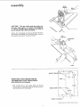
1. Drill six 3/8" holes in your bench. Make sure the top
of vour bench is centered on the tegsso that you don't
drill into the short rail underneath,
14 5/8"
HOLES
FOR
LATHE\
"_----_ ,I
\I , [6,3/16
LOCA'I'ION
0;*
#_OUFFfU'_G
HC_L_;.S
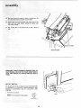
assembly
NOTE: To attach your Lathe to the bench, use the bolts,
nuts and washer you removed when unpacking.
2. Position Lathe on bench and nsert two bolts through
holes in headstock but do not screw on the nuts.
BED
PARALLELTO
EDGE OF BENCH
3. Position the Lathe so that the bed is parallel to the
front of the bench. Check the foot. If the bottom of
the foot is not laying flat on the surface of the bench,
loosen the screw in the foot, tap the screw to loosen
the Iocknut inside. Turn the foot and tighten the screw.
/
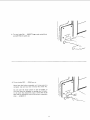
4. Mark the location on the bench of the hole in foot,
5. Remove the Lathe and drill a 3/8" hole to attach the
foot.
6. Position the Lathe and insert the bolts from the toP.
Place a flat washer, a Iockwasher and a nut on the bolts
and tighten the nuts.
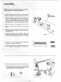
7. Position the motor over the holes. NOTE: When using
a Craftsman double shaft motor, make sure the 5/8" dia.
shaft is to the left when facing the front of the Lath_
FOOl
8. Find four 1/4" - 20 x 1-3/4"' carriage bolts, flat washers
and nuts from among the loose pans.
9. Insert the bolts from the top. Place a flat washer and a
nut on the bolts but do not tighten the nuts at this time,
/
10. Remove the pulley
11.
using the 5/32"
setscrew wrench.
Find four pan head thread cutting screws 3/8" long and
four Iockwashers
from among the loose parts, Attach the
belt guard with these screws and Iockwashers.
©
B"
/
/
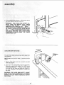
12. Replace the Lathe pulley. Position it so that the end of
the pulley is ftush with the end of the lathe spindle.
t3.
Place the motor
pulley on the motor shaft so that the
small diameter is approximately
t/16"
away from motor.
14. NOTE: When installing the pulley on a 5/8" diameter
motor shaft, make sure that the 3/16" square key furnished with your motor is in place. Then tighten the
setscrew with a 5/32" setscrew wrench.
3/16 x 3/16 KEY
15. When installing
the pulley
on a 1/2" diameter
motor
shaft,
make sure that the adapter
sleeve and 3/1 6"
square key furnished
with your motor are in place. Then
tighten
the setscrew
with
a 5/32"
setscrew
wrench.
16. Place the belt on the pulleys and push the motor toward
the back until all the slack is removed from the belt.
Tighten only two of the motor mounting bolts using a
7/16" wrench.
ADAPTER
SLEEVE
1/2 DtA. MOTOR SHAFT
17.
Place a straightedge
such as a piece of wood, metal or
framing equare across the pulleys to see if they are both
in line. If they are, tighten the other two motor mounting
bolts. If they are not in fine, loosen the two motor bolts
and move the motor sideways..,
tighten the bolts.
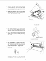
18.
Find four pan head wood
the loose parts.
screws
Attach the belt guard plate
screws. Make sure the plate
1/2"
tong from
to the bench
is PARALLEL
among
with the two
to the belt.
/
/
19. Plug motor cord into outlet on back of switch box. Do
not plug motor cord into power source outlet.
20. Position the two cords as shown and clamp them to the
table With tWO cable clamps. Attach the clamps with
1/2" wood screws
21. Coil up the slack in the cord and tie it with a piece of
tape.
CABLE CLAMPS
\
MOTOR CORD
WARNING: DON'TCONNECTPOWER
CORD TO
ELECTRICAL
OUTLET IN YOUR SHOP UNTIL
YOU ARE READY TO CHECK MOTOR ROTATION.
ON-OFF
I
SWITCH
I
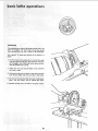
The On-Off Switch has a locking feature. THIS FEATURE
IS INTENDED
TO PREVENT UNAUTHORIZED
AND
POSSIBLE HAZARDOUS
USE BY CHILDREN
AND
OTHERS.
I
1. Insert key into switch,
KEY
NOTE:
Key is made of yellow plastic.
[YELLOW
KEy
f_LAS1 IC
10
f
2.
To turn
and pull
Lathe ON...
INSERT
END of switch out.
3. To turn Lathe OFF...
Never
stop
and
under
switch
lever
PUSH lever in.
heave the Lathe
complete
finger
unattended
you
until
have removed
it has come to a
the
switch
key.
Do not cycle the motor switch
on and off rapidly,
as
this may cause the faceplate
or sanding disc to loosen.
In the event this should ever occur, stand clear of the
face plate or sanding disc until it has come to a complete
stop.,
. retighten
it.
11
assembly
4. To lock switch in OFF position...
HOLD switch IN with
one hand, REMOVE key with other hand.
WARNING:
FOR YOUR OWN SAFETY, ALWAYS LOCK THE SWITCH "OFF".
WHEI_
LATHE IS NOT IN USE . . . REMOVE KEY
AND KEEP IT INASAFE
PLACE...
ALSO,.,
INTHE EVENT OF A POWER FAILURE (ALL
OF YOUR LIGHTS GO OUT) TURN SWITCH
OFF ... LOCK IT AND REMOVE THE KEY.
THIS WILL PREVENT
THE LATHE FROM
STARTING
UP AGAIN WHEN THE POWER
COMES BACK ON,
ROTATION
CHECK MOTOR
ROTATION
TERMINAL
COVER
The Lathe must rotate counterc ockw se when viewed from
the spindle end.
NOTE: Make sure the spur center is removed from the
spindle.
1. Plug the Lathe power cord in[o a properly' grounded
outlet (See page 41,
2. Stand clear of the Lathe spindle and turn the switch ON,
Notice the rotation
of the spindle,
If it is NOT turning
COUNTERCLOCKWISE
.
. Remove the Lathe power
cord plug from the outlet and change the rotation
of
the motor according to the directions furnished
with
the motor.
WARNING:
FOR YOUR OWN SAFETY,
MAKE
SURE PLUG IS NOT CONNECTED
TO POWER
SOURCE OUTLET WHEN CHANGING
MOTOR
ROTATION.
12
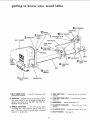
getting
to know
your
wood
Bathe
6HANDWHEEL
TAILSTOCK
10
INDEX PIN
SPUR
CENTER
._,_
_L_
RAM
cuP CENTER
3 SPINDLE,
ocK
7 TA,'S,OCK
RAM
HOLE
BELT GUARD
TOOL REST
TOOL REST
BASE
TOOL
11TAI
LS//KTOC
FOOT
TAILSTOCK
LOCK
SPEED
_-
TOOL REST
LOCK
BED
ON-OFF
SWITCH
1
BELTGUARD
LOCK
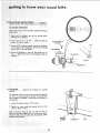
1. BELT GUARD LOCK.,.
guard during operation.
HEADSTOCK
Locks the hinged part of the
4, TOOL REST LOCK
rest base.
...
Clamp the tool rest to the tool
5. TOOL REST BASE LOCK..,
to the bed.
2. INDEX PIN...
Engages with the spindle pulley to determine equal spacing for cuts for fluting or reeding, or for
dividing face plate work. DO NOT USE FOR REMOVING
FACE PLATES.
6. HANDWHEEL...
Adjusts the tailstock ram.
7. TAll_STOCK RAM LOCK...
tailstock.
3. SPINDLE LOCK HOLE . . . For removing face plates
or sending discs, Insert a setscrew wrench, large nail or
bolt in the hole to hold the spindle while unscrewing
face plate or sanding disc.
8. TAILSTOCK
LOCK...
9, ON-OFF SWITCH,..
13
Clamps the tool rest base
Clamps the ram in the
Clamps the tailstock
See page 10.
to the bed,
now
10.
wood
lathe
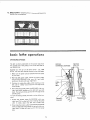
UR CENTER AND CUP CENTER
. . , are used for
ndle turning and should always be in alignment,
ALIGNING
CENTE
RS
If the centers are not n I ne as shown, make the following
adjustments.
1, Make sure the tailstock
checking for alignment,
2.
and ram ere locked
Loosen the screw in the foot
loosen the Iocknut
inside,
. . . TAP the
when
screw
to
HEAOST
rU
3. Using a 3/16" setscrew wrench, loosen the setscrew
on the back of the headstock. The screw _slocated
about 1-3/4" from the bottom.
3/16"
4. Swing the tailstock
so that the two points
are in
line . ., tighten the setscrew in the headstock and the
tailstock
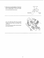
11. TAILSTOCK...
tuming,
The tailstock
supports
contains
the workpiece for spindle
a brass screw which
bears
against
the "key"
on the underside
vents excessive "looseness"
the tailstock,
of the bed. This screw pre(rocking
back and forth]
of
'L Loosen the Iocknut
a 7/16"
using
TocK
2. Tighten
the screw moderately
loosen it about 1,/4 turn.
wrench,
against the
key,
then
Slide the tagstock
along the bed. tf it does not stick or
bind in any one spot, tighten the nut. If it binds or sticks,
loosen the screw only enough so that the tailstock slides
smoothly along the bed.
SCREW
14
LOCKNUT
KEY
12. &_EED CHART.
various
indicates general
sizes of workpieces,
CHANGING
The
the
belt
run 2250
speeds for
SPEEDS
is shown
outside
_ecommended
positioned
end of the
on the
pulleys,
This
second
steps from
causes the lathe
ROTATE
COUNTERCLOCKWISE
to
MOTOR
PULLEY
R.P.M.
Suppose you wish to run the
R.P.M. You must shift the belt
1. Make
sure the power
in your
is removed
from
the outlet
shop.
2. With the belt guard
COUNTERCLOCKWISE
pushing
raised, rotate
the motor
pulley
with
your left
hand while
on the belt with
3. Continue
belt until
motor
cord
lathe slower - say, 1350
inward to the third steps.
your
right
hand.
to rotate the pulley
while
pushing on the
it "climbs'"
down into the third step of the
ON
BELT
pu ffey.
4. Now rotatethe
spindle
pulley
CLOCKWISE
with
your
right hand while pushing on the belt with your left
hand. The belt will climb up into the third step of the
spindle
pulley.
To make the lathe go faster,
the belt
must be shifted
out
ward.
1. Rotate
right
until
the
spindle
putley
hand. Pull on the
it climbs
clown
2. Nowrotatethe
motor
CLOCKWISE
belt while
into
the
with
your
PULLEY
rotating
the pulley
next
smaller
step.
pulleyCOUNTERCLOCKWlSE
with
yourleft
handwhile
pulling
right
hand.
The belt will
climb
on the belt with
your
up into the next targer
step.
15
4th
SP|NDLE TURNING.
If you have neverdoneany amountof wood turning,
we suggestthat you pract ce usingthe variouswood
turning tools. Start with a small spindle turning.
Be sure to study the "Handbook"
with your
lathe,
which you
it explains and illustrates
use of the turning
tools,
res-cand other information
1 Select a piece of wood
the positioning
receive_
the correct
of the tool
to help you gain experience,
2" x 2" x 12".
2. Draw diagonal lines on each end to locate the centers.
3. Ononeend, makeasawcut approximately 1/16"deep
on each d_iagonal line, This is for the spur center,
4. The other end is for the cup center. Place the point of
the cup center On the wood where the diagonal lines
DIAGONAL LINES
ON BOTH ENDS
cross
5, Drive the cup center into the wood. Use a wooden
mallet Or a plastic hammer, If you don't have one, use
asteel hammer, but put a piece of wood on the end of
the cup center tO protect it.
/
/
j-
/
/
6, Remove the cup center and drive thespur center into
the other end of the wood. Make sure the spurs are in
the saw cuts. Remove the spur center.
/
7, Make sure the centers and the hole in the spindle and
the tailstock ram are clean, Insert the centers and tap
them in lightly with a piece of wood. Do notdrive them
in.
/
/
/
/
/
/-
J
8, Put a drop of oil on the wood where you drove in the
cup center. This will lubricate the wood while it is
turning.
/
/
9. Place the wood between the centers and lock the tail*
stock.
10. Move the cupcenter intothewood
by turning the hand
wheel. Make sure that the cup center and spur center
are "seated" into the wood the same as they were
when you drove them in, Rotate the wood by hand
while turning the hand wheel.
16
1/8"
11. Adjust the tool rest approximately
1/8" away from
the corners _f the wood and 1/8" above the center line.
Note the angled position
of the tool rest base.
Lock
the tool
rest base and the tool rest.
TOOL REST
Look
turning
at the
speed
up to 18"
"roughing",
Move
slowest
speed.
Rotate
the wood
do not strike
chart,
Notice
that
e 2"
square
long should
run at 875 R.P,M.
for
the
on the
the
V-belt
pulleys
by hand to make sure that
the tool
to
the corners
rest.
17
WOOD
INDEXING
The spind e pu ey contains 36 equally spaced holes. The
index p_n engageswith these hotes to keep the spindle
from turning while you put a mark on the workoiece
For example:
wheel:
TO locate the position of six spokes in a
I. Pulltheindexpinoutwardandturnitso
that thesmall
cross pin slips into the slot. This will allow the index
pin to engage in one of the holes in the pulley and prevent the spindle from turning.
2. Adjust the tool rest approximately
and make a mark.
3. Pull outthe
until
the
index
pin
pin and slowly
slides
into
the
at the centerline
rotate
next hole
the workpiece
in the
pulley.
4. Do this six times and put the next mark on theworkpiece. The two marks will be snaeed 60 ° apart.
5. Spindle turnings can be divided in the same manner.
18
\
maintenance
WARNING:
FOR YOUR OWN SAFETY, TURN
SWITCH "OFF"
AND REMOVE PLUG FROM
POWER SOURCE OUTLET BEFORE MAINTAINING OR LUBRICATING
YOUR LATHE.
Frequently
the motor.
blow
out
any dust that
A coat of automobile-type
may accumulate
to keep the surfaces clean
stock to more more freely,
and allow
If the power cord is worn or cut,
have it replaced immediately,
or damaged
rest and tail-
in any way,
inside
For motor maintenance, follow
motor.
wax applied
the tool
to the bed will
instructions furnished with
help
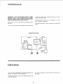
WIRING
DIAGRAM
WHITE
WHITE
MOTOR
OUTLET
Insulated
Cap, Flag
Terminal
_REEN
.....
m
Uubrication
All of the BALL BEARINGS are packed with grease at the
factory. They require no further lubrication.
Periodically lubricate the ram in the tailstock
or No. 30 engine oil.
with
For motor
the motor.
No. 20
19
lubrication,
follow
instructions
furnished
with
trouble
shooting
TROUBLE
PROBABLE
TROUBLE
1. Defective
Defective
Motor will not run.
Lathe
slows down
when
turning
On-Off
switch
SHOOTING
CHART
REMEDY
CAUSE
switch.
cord.
1. Replace
defective
parts before
using
Lathe
again.
Defective switch
box receptacle.
2. Motor protector
open,
(only if your motor is
equipped with
an
overload protector).
Other cause
2. Consult Sears Service• Any attempt
to repair this
motor may create a HAZARD
unless repair is
done by a qualified
service technician.
Repair
service is available at Voter nearest Sears Store•
1. V-belt
1. Adjust
too
loose
belt tension,
see Assembly
Section.
l
Tailstock
rocks
back and forth
excessively •
Headstock
1• Brass adjusting
loose.
i
screw is too
1. Setscrew
burns at
tailstock
end.
"Getting
To Know
i
loose
not
tight.
1. Tighten setscrew. See Section,
Know Your Lathe".
on bed.
Wood
1. Adjust screw. See Section,
Your Lathe".
1, Cup center
=
too
tight
or not
lubricated.
1. Back off tailstock
ram and lubricate
cup center. See Basic Lathe Operation
Section,
2O
"Getting
"Spindle
Turning."
To
recommended
accessories
RECOMMENDED
ACCESSORIES
IN CANADA,
SEE LOCAL SIMPSONS°SEARS
STORE
OR CATALOG
FOR ACCESSORY
SELECTION AND NUMBERS.
ITEM
CAT.
Work
Bench
.........
NO.
9-10266,9-10278.9-10271
Motor
Pulley
(Four
Step)
1/2"
Bore
......
9-27921
Motor
Pulley
(Four
Step)
5/8"
Bore
......
9-27922
Drill Chuck 1/2" Capacity with
No. 1 M.T. Shank
..................
9-22342
Work Arbor 1/2" Dia. with
No. 1 M.T. Shank
..................
Screw
Ball
No.
Center
with
8earing Center
1 M.T. Shank
BO°Center
with
No.
9-215,32
No. 1 M.T. Shank
......
9-21162
with
..................
9-21122
1 M.T. Shank
........
9-21102
Face Plate, 4" Dia. with 3/4"
No. 16 Threads
.....................
9-2489
Face P]ate Including Spurs and Screw Center
3"" Dia. with 3/4" No. 16 Threads
........
9-20912
9"" Dia. Sanding
No. 16 Threads
Disc Only
..........
9_24906
Turning
Tools
Draw Bolt with
...............
1/4" No. 20 Threads
Power
Tool
Radial
Saw
Know
Saw
Bowl
Turning
The
were
above
3/4"
..........
(SEE CATALOG)
......
9-21542:
Handbooks
........................
Table
Face Plate
How
with
9-2917
........................
Toolrest
6" with
9-2918
.................
3/4"
No.
recommended
available
at
the
9-24903
16 Threads
accessories
time
21
this
.....
9-24904
are current
manual
and
was printed.
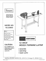
CRAFTSMAN
12-INCH
WOOD TURNING
LATHE
MODEL
NO. 23800
7 89
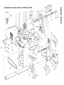
Figure
13
10
57
1
11
12
/
\
68
20
19
12
11
23
28
29
30
/
31
32
63
25
21
53
52
51
26
CRAFTSMAN
-_e¥
Part No.
12" WOOD-TURNING
LATHE
Key
No,
Description
O.
1
2
3
4
5
6
7
8
9
10
11
12
13
14
15
16
17
18
Po
1#
7O004
63467
62376
STD503103
5617O
I STD610805
I STD600602
70008
STD60O605
56110
18229
38884
70014
56614
18994
38896
56613
56120
Guard
Bearing, Ball
Rmg. Retammg
Headstock
Plunger
Pm
25
26
27
28
29
30
31
32
33
34
35
36
37
Stock
NOTE:
Key
*ScrewSoc
56190
56625
56217
56212
I
56634
I
70007
I
STD541525
60262
120399
56213
STD623117
56633
60156
Hardware
lt,,m
6-32 x 1/4
42
56628
STD641025
38631
70016
56222
70001
70012
70011
60283
STD551037
70002
Hd
4
43
44
45
46
47
48
10-32 x 3/8
1-5/8
49
Set 3/8
16x
50
51
May Be Purchased
and handhng
through
]o avoid
Ban et, Lock
Tadstock
Assumbly
Complete
Consisting
Item'. 25, 26.27,
28.29,
30.31,
32, 36.
55
56
1/2
57
58
59
60
61
62
63
64
65
66
67
68
69
with
Point
37, 38, 39, 41,42,
and 43
Screw Slotted Hd Set 1/4-20_
Nut Hex 1/4-20
Barrel. Lock
R_st, Tool
Holder, Tool Rest
Hub Assembly
Loci<
Bracket, Tool
Clamp, Sho_
Nut
Washer. 3/8
Department
h_zdware
items (idenLttted
shlpf_h]g qrld hand!l_g
chalgPs
Switch, Locking
*Nut, He> No 10-32
"Lockwasher.
I',!o 10
Box, Junction
Rehef. Strain
Nut"U'"
Chp
Cord (w!Plug)
Cramp
Washer
Screw, Wing
*tWrench
Hex 5/32
• lWre_ch Hex 3/16
Rest 6" Tool
t Pdlh;y
Spring
Bag of Loo_e Parts (No[ Illustrated)
Owner's Manual (Not Illustrated)
Rete_l Stores or Cdtalog
by ") "_uch as nt_ts, _Qews, washers, e'c
you ma_f oDta.ll
mo_t el tli_r
i_call_
1-1/4
Tool Rest and Clamp AssembLy Consisting
of
Items 29.31,
32.36,
37.38,
44, 45, 46. 47,
48, 49, 50 and 69
Tube Assel'n blv
"Belt "Vee"
1/2 x 31
Switch, Panel
I
of most Sears or S_mpsons-Seals
oF
Rest
Locally
the Hardware
charges _or standard
item5 t)y mall _lrleco[l{)N)lC.al
Screw
56130
STD304370
70010
60267
STD541110
STD551210
70009
37818
37530
60211
63418
805146
30540
60145
37911
70019
805265
6300q
70016
70017
52
Housing, Tadstoek
Nut, Stud
Hub, Assembly
Lock
Nut, Lock 1 _4-28
Grip
• Nut Square 5/16-18 x 9,'10 x 7/32
Foot, Rear
*Screw Pan Hd 5/16-18 x 1-3/4
Spacer
Screw Hex Washer Hd No 10-24 x I
Item
Description
5/16
tNo. 1 Morse Taper Cup Center
Spindle, Tadstock
Wheel, Hand
May be secured
sh,pp,.g
41
18x
Headstock
Assembly
Complete
Consisting
of Items 4, 5, 10, 11, 12, 13. 14, 15, 16, 17
19, 20 and 23
I
Standard
¢
12
items 63 and 64
Spring
Housing, Plunger
Plunger and HOLESlng Assembly
Complete
Constst_ngof
Items 14 15. 16 and 17
Spmdle
tNo
1 Morse Taper Spur Center w_th Point
Point
56611
56180
56619
60256
I STD503705
I
70006
Part No.
60308
56629
70005
Set5116
*Screw Type 23 Pan No
Guard. Prate
'Screw Type 23 Pan No
Collar w_th Set Screw
NO. 1 !3.23800
38
39
4O
includes
Pultey Includes Key No
Screw Pan Hd TypeA8×
19 I
20
21
22
23
24
Assembly,
Cap Flag Term
Outlet
*ScrewSoc
Hd
MODEL
Order
Houses
, make buyu_g these
owners
manual
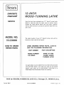
SERVICE
12--INCH
WOOD- TURNING
Now that you have purchased
your
should
repair
a need ever exist
for
LA THE
12" Wood-Turning
Lathe
parts or service, simply
contact any Sears Service Center and most Sears, Roebuck
and Co. stores. Be sure to provide all pertinent facts when you
call or visit.
MODEL NO.
113.:23800
The model number
of your
12" Wood-Turning
Lathe will
found on a plate under the belt guard.
HOW TO ORDER
REPAIR PARTS
WHEN ORDERING REPAIR PARTS, ALWAYS
GIVE THE FOLLOWING INFORMATION:
PART DESCRIPTION
PART NUMBER
MODEL NUMBER
All
NAME
OF ITEM
12-INCH WOOD
TURNING LATHE
113.23800
parts listed may be ordered from any Sears Service Center
and most Sears stores. If the parts you
need are not stocked
Iocatty, your order will be electronically
transmitted
Sears Repair Parts Distribution
Center for handling.
Sold
Part No. 70017
by
SEARS,
be
PoOEBUCK
AND
CO.,
Form No. SP4009-6
Chicago,
IL.
60684
to a
U.S.A.
Printed in U.S.A.
4/7