1
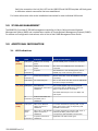
Installation Instructions
MUM200-2
IP DSLAM Multiplexer Module with Dual Uplink Interface Capacity
CAUTION Net to Net Technologies strongly recommends the use of proper electrostatic discharge (ESD) precautions when
handling this equipment.
1.0
INSTALLATION
1.1
Unpack and Inspect the Multiplexer Uplink Module (MUM)
If there is visible damage, do not attempt to install the MUM200-2; contact Customer Support at 1877-638-2638 (001-603-427-0600 for international customers) or [email protected].
1.2
Install an Uplink Interface Module (UIM) on the MUM200-2
A UIM provides the upstream network connection, via the MUM200-2, for Net to Net Technologies' IP
DSLAMs; neither an IP DSLAM nor a MUM200-2 can function without a UIM. Any of Net to Net's
available UIM models, with the exception of the UIM-1000T and UIM-1000F, may be installed on a
MUM200-2 .
z
z
Select a port on the MUM200-2 for UIM installation; either port (1 or 2) may be used. Although
not required for operational purposes, if redundancy is desired two UIMs may be installed on a
MUM200-2, one in each port.
Remove the blanking plate from the selected port.
CAUTION Blanking plates should be stored for possible future use: if a UIM is removed from a
MUM200-2, it must be replaced with either another UIM or a blanking plate. DO NOT
OPERATE A MUM200-2 WITH AN OPEN UIM PORT.
z
z
z
z
Carefully slide the faceplate of the UIM under the lip of the MUM200-2 faceplate at the
selected port opening such that the UIM circuit board is facedown and the label shows through
the MUM200-2 port opening with the UIM model name along the right-hand edge.
Ensure that the mounting holes on the UIM are lined up with the corresponding pems on the
MUM200-2 circuit board and that the board-to-board connector key pins are properly aligned.
Gently press down with even pressure on all four corners of the UIM until the board-to-board
connector is fully seated.
Secure the UIM circuit board to the MUM200-2 circuit board, at the pems, with the (4)
provided panhead screws.
220-0000069 rev 04
z
1.3
Secure the UIM faceplate to the MUM200-2 faceplate using the (2) provided beige flathead
screws.
Install the MUM200-2 in an IP DSLAM Chassis
The IPD12000 is a fourteen slot chassis; slots 1-12 are reserved for interface modules (such as the
SIM2000-24) and slots 13-14 are reserved for MUMs. Although not required for operational
purposes, if redundancy is desired two MUMs may be installed in the IPD12000, one each in slot 13
and slot 14. The IPD4000 is a five slot chassis; slots 1-4 are reserved for interface modules and slot
5 is reserved for a MUM.
z
Align the MUM200-2 with the slot module guides of the chosen slot for installation (either slot
13 or 14 on the IPD12000 or slot 5 on the IPD4000).
z
Slide the MUM200-2 firmly into the chassis. DO NOT USE EXCESS FORCE.
z
Tighten the fastening screws on the MUM200-2 faceplate.
z
Verify that the PWR (Power) LED on the MUM200-2 faceplate is illuminated.
1.4
Connect the UIM(s) to the Network
Connect the network line(s) according to the UIM model type(s) installed in the MUM200-2:
1.4.1
UIM-10/100
Plug your Ethernet cable into the RJ45 Ethernet port on the UIM-10/100 faceplate. The UIM10/100 connects to a router or a PC with a straight-through cable and to a hub or a switch
with a crossover cable.
Verify the connection: solid illumination of the Lnk (link) LED on the UIM-10/100 faceplate
indicates an Ethernet uplink connection has been established. The UIM-10/100 Ethernet port
is 10/100 auto-negotiating.
NOTE Net to Net Technologies recommends that the remote device with which you are connecting be
configured to auto-negotiate (if applicable) prior to establishing your Ethernet connection.
1.4.2
UIM-T1 and UIM-E1
Plug your T1/E1 cable into the RJ45 T1/E1 port on the UIM-T1 or UIM-E1 faceplate. The UIMT1 and UIM-E1 connect to a T1/E1 network extender provider unit (TNE1500-P, TNE1500-P12, ENE2000-P or ENE2000-P-12) via T1/E1 line.
Verify the connection: the Lnk (link) LED on the UIM-T1 or UIM-E1 faceplate will flash green to
indicate a network connection has been established.
1.4.3
UIM-DS3 and UIM-E3
Plug your DS3/E3 cables into the corresponding Rx and Tx BNC ports on the UIM-DS3 or UIME3 faceplate. The UIM-DS3 and UIM-E3 connect to a DS3/E3 network extender provider unit
(DNE4500-P, DNE4500-P-12, ENE3400-P or ENE3400-P-12) via DS3/E3 line.
220-0000069 rev 04
Verify the connection: the Lnk (link) LED on the UIM-DS3 and UIM-E3 faceplate will flash green
to indicate a network connection has been established.
For further information refer to the Installation Instructions for each individual UIM model.
2.0
IP DSLAM MANAGEMENT
The MUM200-2 provides IP DSLAM management capability via Net to Net's web-based Network
Management System (NMS) and a scaled-down version of Simple Network Management Protocol (SNMP).
For access and configuration instructions, refer to Net to Net's NMS Management User Guide.
3.0
ADDITIONAL INFORMATION
3.1
LED Indications
LED
State
Indication
Additional Information
PWR
(Power)
solid green
MUM200-2 is receiving
power
Both IP DSLAM power terminals are connected.
solid amber
MUM200-2 is receiving
power
One of the two IP DSLAM power terminals are
connected.
no
illumination
no power
The MUM200-2 is not receiving power (the IP
DSLAM may not be receiving power either).
no
illumination
all fans are functioning
All four of the fans on the IP DSLAM fan card are
functioning.
solid amber
non-functioning fan
One or more of the four fans on the IP DSLAM fan
card are no longer functioning.
Fan
Lnk (Link) solid green
direct Ethernet
The Lnk LED applies only to direct physical
management connection is connections with the MGMT port; it does not
established
apply to uplink network connections.
The MGMT Ethernet port runs at 10 Mbps and
Half Duplex.
UIM Lnk
(Link)
220-0000069 rev 04
no
illumination
no direct connection via
the MGMT port is
established
solid green
UIM-10/100 Ethernet
uplink connection is
established
For further information regarding UIM-10/100
LEDs, please refer to the corresponding UIM
Installation Instructions.
flashing
green
UIM-T1/E1 or UIM-DS3/E3
uplink connection is
established
For further information regarding UIM-T1/E1 or
UIM-DS3/E3 LEDs, please refer to the
corresponding UIM Installation Instructions.
no
illumination
no uplink connection is
established
Applicable to all UIM models types.
3.2
Regulatory Compliance for Class A Equipment
The following regulatory compliance information applies to a MUM200-2 as installed in one of Net to
Net Technologies' IP DSLAMs.
3.2.1
US Federal Communications Commission (FCC)
Note: This equipment has been tested and found to comply with the limits for a Class A digital
device, pursuant to part 15 of the FCC Rules. These limits are designed to provide reasonable
protection against harmful interference when the equipment is operated in a commercial
environment. This equipment generates, uses and can radiate radio frequency energy and, if
not installed and used in accordance with the instruction manual, may cause harmful
interference to radio communications. Operation of this equipment in a residential area is
likely to cause harmful interference in which case the user will be required to correct the
interference at his own expense.
Caution: Changes or modifications not expressly approved by the manufacturer could void the
user’s authority to operate the equipment.
3.2.2
Industry Canada
This Class A digital apparatus complies with Canadian ICES-003.
Cet appareil numérique de la Classe A est conforme à la norme NMB-003 du Canada.
3.2.3
Europe
This Class A product complies with European Norm EN55022.
Warning: In a domestic environment this product may cause radio interference in which case
the user may be required to take adequate measures to correct the situation.
220-0000069 rev04
© Copyright 2002 Net to Net Technologies, Inc.
™ The Net to Net Logo is a trademark of Net to Net Technologies, Inc.
Worldwide Headquarters
Net to Net Technologies
112 Corporate Drive
Portsmouth, NH 03801
USA
+1 877-638-2638
220-0000069 rev 04
http://www.NetToNet.com/
[email protected]
EMEA Headquarters
Net to Net Technologies
Victoria House 19 Park Way
Newbury Berkshire RG14 1EE
UK
+44 (0) 1635 570950