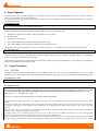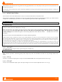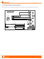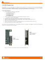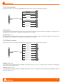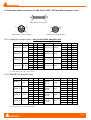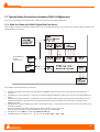
1
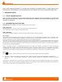
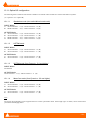
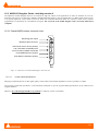
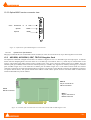
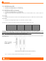
Mykerinos-X
Mykerinos
(PCI eXpress version)
(PCI version)
The Audio Processing Board
User Manual
Version: DOC-2.15 (July 2009)
©2001-2009 Merging Technologies
Merging Technologies
Le Verney, CH-1070 Puidoux Switzerland
Tel: +41 21 946 04 44 ● Fax: +41 21 946 04 45
www.merging.com
Please read the following information very carefully before attempting any installation. Failure to comply with the precise
instructions may result in damage to your Merging hardware. Please read this entire section of the manual carefully before.
1 Important notice
1.1
STATIC DANGER NOTICE:
Please note that the Mykerinos/-X board contains delicate electronic components that can be damaged or even destroyed
when exposed to static electricity. Take all necessary precautions not to discharge static electricity when touching any of the
Mykerinos/-X components.
1.2
INFORMATION FOR THE USER:
Mykerinos/-X and its daughter card comply with the following specifications:
EMC Emissions
EN 55022 : 1994 /A1 : 1995 /A2 : 1997 Class A ITE emissions requirements (EU)
FCC 47 CFR Part 15 Class A emissions requirements (USA)
EMC Immunity
EN 50082-1: 1992 EMC residential, commercial and light industrial generic immunity standard.
FCC Notice
This product has been tested and found to comply with the limits for a Class A digital device, pursuant to Part 15 of the FCC rules.
Operation is subject to the following two conditions: (1) This device may not cause harmful interference, and (2) This device must
accept any interference received, including interference that may cause undesired operation.
These limits are designed for providing reasonable protection against harmful interference in a residential installation. This equipment
generates, uses and can radiate radio frequency energy and, if not installed and used in accordance with the instructions contained in
this manual, may cause harmful interference to radio and television communications. However, there is no guarantee that interference
will not occur in a particular installation.
NOTE: Connecting this device to peripheral devices that do not comply with CLASS A requirements or using an unshielded
peripheral data cable could also result in harmful interference to radio or television reception. The user is cautioned that any changes
or modifications not expressly approved by the party responsible for compliance could void the user’s authority to operate this
equipment. To ensure that the use of this product does not contribute to interference, it is necessary to use shielded I/O cables.
CE Notice
Such a
•
•
marking is indicative that this system’s devices meet the following applicable technical standards:
EN 55022 – “Information Technology Equipment - Radio disturbance characteristics Limits and methods of measurement”
EN 50082-1: 1992 – “Electromagnetic compatibility – Generic immunity standard Part 1:Residential, commercial, and light
industry”
This product is classified for use in a typical Class A commercial environment, and is not designed or intended for use in other EMC
environments. The user of this product is obliged for proper use and installation of the product and for taking all steps necessary to
remove sources of interference to telecommunications or other devices.
-2-
2 Mykerinos/-X Waranty Information
This product is warranted to be free of defects in materials and workmanship for a period of one year from the date of purchase.
Merging Technologies, Inc. extends this Limited Warranty to the original purchaser.
In the event of a defect or failure to confirm to this Limited warranty, Merging Technologies, Inc. will repair or replace the product
without charge within sixty (60) days. In order to make a claim under this limited warranty, the purchaser must notify Merging
Technologies, Inc. or their representative in writing, of the product failure. In this limited warranty the customer must upon Merging
Technologies, Inc. request, return the product to the place of purchase, or other local designation, for the necessary repairs to be
performed. If the consumer is not satisfied with the repair, Merging Technologies, Inc. will have the option to either attempt a further
repair, or refund the purchase price.
This warranty does not cover: (1) Products which have been subject to misuse, abuse, accident, physical damage, neglect, exposure to
fire, water or excessive changes in the climate or temperature, or operation outside maximum rating. (2) Products on which warranty
stickers or product serial numbers have been removed, altered or rendered illegible. (3) The cost of installations, removal or
reinstallation. (4) Damages caused to any other products.
-3-
3 Table of Contents
1
IMPORTANT NOTICE ................................................................................................................................................................. 2
1.1
1.2
STATIC DANGER NOTICE:................................................................................................................................................... 2
INFORMATION FOR THE USER: ......................................................................................................................................... 2
2
MYKERINOS/-X WARANTY INFORMATION ....................................................................................................................... 3
3
TABLE OF CONTENTS ............................................................................................................................................................... 4
4
INTRODUCTION .......................................................................................................................................................................... 6
5
MYKERINOS/-X FEATURES OVERVIEW .............................................................................................................................. 6
5.1
5.2
6
MYKERINOS SPECIFIC: ............................................................................................................................................................... 6
MYKERINOS-X SPECIFIC: ........................................................................................................................................................... 6
MYKERINOS-X SPECIFICATIONS .......................................................................................................................................... 7
6.1
6.2
7
MYKERINOS-X BLOCK DIAGRAM .............................................................................................................................................. 7
MYKERINOS-X ON-BOARD CONNECTORS AND JUMPERS .......................................................................................................... 8
MYKERINOS SPECIFICATIONS............................................................................................................................................... 9
7.1
7.2
MYKERINOS BLOCK DIAGRAM .................................................................................................................................................. 9
MYKERINOS ON-BOARD CONNECTORS AND JUMPERS............................................................................................................... 9
8
MYKERINOS/-X BRACKET VIEW ......................................................................................................................................... 10
9
SYNC FEATURES ....................................................................................................................................................................... 11
9.1
SIGNAL DESCRIPTION .............................................................................................................................................................. 11
9.1.1
CVS1 IN .......................................................................................................................................................................... 11
9.1.2
WCKIO (Old CVS2In)..................................................................................................................................................... 12
9.1.3
CVS OUT ........................................................................................................................................................................ 12
9.1.4
LTC IN ............................................................................................................................................................................ 12
9.1.5
LTC OUT ........................................................................................................................................................................ 12
9.2
BREAKOUT CABLE PIN-OUT DESCRIPTION (J2) ........................................................................................................................ 13
9.3
VIDEO/TC HEADER PIN-OUT DESCRIPTIONS (JP2) ................................................................................................................... 14
10
10.1
11
11.1
12
MYKERINOS-X MONITORING HEADPHONE FEATURES (J3) .................................................................................. 15
MONITORING OUTPUT CHARACTERISTICS ................................................................................................................................ 15
MYKERINOS MONITORING HEADPHONE FEATURES (J3)....................................................................................... 16
MONITORING OUTPUT CHARACTERISTICS ................................................................................................................................ 16
MYKERINOS/-X MODULAR I/O DAUGHTER CARDS ................................................................................................... 17
12.1 ADAT I/O DAUGHTER CARD .................................................................................................................................................. 17
12.1.1
Optical I/O configuration................................................................................................................................................ 18
12.1.1.1
12.1.1.2
12.1.1.3
12.1.1.4
Standalone mode (also called Mono-board mode)...................................................................................................................... 18
HDTDM mode............................................................................................................................................................................ 18
XDTDM mode (from Pyramix v. 5.0 and higher) ...................................................................................................................... 18
MassCore mode (from Pyramix v. 6.0 and higher) ..................................................................................................................... 18
12.2 MADI I/O DAUGHTER CARDS - INCLUDING VERSION II .......................................................................................................... 19
12.2.1
Coaxial MADI version connector view ........................................................................................................................... 19
12.2.1.1
Coaxial Cable Specifications ...................................................................................................................................................... 19
12.2.2
Optical MADI version connector view ............................................................................................................................ 20
12.3 AES-EBU, AES-EBU II, SDIF, TDIF I/O DAUGHTER CARD ................................................................................................. 20
12.3.1 AES-EBU without SRC ................................................................................................................................................... 21
12.3.2 AES-EBU with SRC on 8 channels.................................................................................................................................. 21
12.3.3
SDIF ................................................................................................................................................................................ 21
12.3.4
TDIF ............................................................................................................................................................................... 21
12.4 DUAL DAUGHTER CARD ........................................................................................................................................................ 22
12.4.1
Card Features ................................................................................................................................................................. 22
-4-
12.4.2 Front connector .............................................................................................................................................................. 23
12.4.3 Rear 0 connector ............................................................................................................................................................. 23
12.5 BREAKOUT CABLE CONNECTORS FOR AES, AES II, SDIF, TDIF AND DUAL DAUGHTER CARDS ........................................... 24
12.5.1 Analog I/O breakout cable – Only for the DUAL daughter card .................................................................................. 24
12.5.2 AES/EBU I/O breakout cable.......................................................................................................................................... 24
13
TYPICAL AUDIO CONNECTIONS BETWEEN DUA II & MYKERINOS..................................................................... 25
13.1
13.2
13.3
14
AUDIO FOR VIDEO WITH SONY DIGITAL BETACAM USERS .................................................................................................... 25
AUDIO FOR VIDEO WITH SONY ANALOG BETACAM USERS ................................................................................................... 26
MERGING TECHNOLOGIES PYRAMIX 6.X DAW WITH SURROUND MONITORING ..................................................................... 27
TYPICAL AUDIO CONNECTIONS BETWEEN SPHYNX & MYKERINOS ................................................................. 28
14.1
14.2
14.3
15
AUDIO FOR VIDEO WITH SONY® DIGITAL BETACAM USERS ................................................................................................. 28
AUDIO FOR VIDEO WITH SONY® ANALOG BETACAM USERS ................................................................................................ 29
MERGING TECHNOLOGIES PYRAMIX 6.X 24 CHANNELS HIGH RESOLUTION SETUP ................................................................. 30
MYKERINOS POWER CONSUMPTION ............................................................................................................................ 31
15.1
15.2
15.3
15.4
15.5
15.6
15.7
15.8
15.9
15.10
15.11
MYKERINOS-X MOTHERBOARD (ALONE) ................................................................................................................................. 31
MYKERINOS MOTHERBOARD (ALONE) ..................................................................................................................................... 31
ADAT DAUGHTER CARD ......................................................................................................................................................... 32
MADI 1 DAUGHTER CARD ....................................................................................................................................................... 32
MADI 2 DAUGHTER CARD ....................................................................................................................................................... 32
AES-EBU DSD (W/O SRC) DAUGHTER CARD ......................................................................................................................... 32
AES-EBU SRC DAUGHTER CARD ........................................................................................................................................... 32
AES-EBU II DSD (W/O SRC) DAUGHTER CARD ..................................................................................................................... 33
AES-EBU II SRC DAUGHTER CARD ........................................................................................................................................ 33
SDIF OR TDIF DAUGHTER CARD ......................................................................................................................................... 33
DUAL (ANALOG – AES/EBU) DAUGHTER CARD ................................................................................................................ 33
16
MOTHERBOARD 3.3V POWER SUPPLY (TOO WEAK ON SOME INTEL BOARDS) .............................................. 34
17
CONTACTING MERGING .................................................................................................................................................... 35
-5-
4 Introduction
This document presents and describes the third and fourth generations of Merging hardware/software solutions, high performance,
cost effective audio processing cards. The MYKERINOS is a third generation PCI based board. The MYKERINOS-X is a fourth
generation PCI Express based board.
5 Mykerinos/-X Features Overview
Mykerinos is Merging's answer to create a leading edge high performance audio processing card solution. It builds upon over 10 years
of experience designing and manufacturing PC based Audio Cards and incorporates hundreds of users feedbacks into a compact
flexible fourth generation solution.
Here is a quick summary of features:
•
•
•
•
•
•
•
•
5.1
Driver support for Windows XP/Vista
Very cost effective
Support for all sampling rates from 32 kHz up to 192 kHz, as well as DSD and DXD.
Open Plug-In (all C-code) architecture supporting Surround-sound and DVD formats
Highly flexible modular I/O architecture can be tailored to user's needs by the use of dedicated daughter boards. This I/O
modularity offers a unique opportunity to meet a wide range of market requirements
Current Audio I/O daughter card options include ADAT - S/PDIF, MADI, AES/EBU, AES/EBU II, TDIF, SDIF and DUAL
Very high performance card capable of high track playback (up to 64 tracks) and vast I/O capabilities (up to 64 channels)
Multiple cards interconnected through XDTDM (eXtreme Definition Time Domain Multiplex) bus with support of up to 512
audio channels
Mykerinos specific:
•
•
•
•
•
5.2
PCI V2.1 compliant. Supports both 5 Volts and 3.3 Volts PCI environments
Based on 2nd generation Philips Trimedia 32 bit floating point processing VLIW technology
High Performance (upto > 400 MFlops sustained, 800 MB/s SDRAM interface, etc.)
On board Sync Connector, which includes Video Sync I/O supporting PAL, NTSC and all trilevel HDTV rates, VITC reader
and generator, LTC reader and generator and built-in time code insertion into Video window.
2 channel 24 bit 96 kHz on-board monitoring output
Mykerinos-X specific:
•
•
•
•
•
PCI Express v1.0a, full x1 PCI Express throughput
Based on 3rd generation Philips Nexperia 32 bit floating point processing VLIW technology
High Performance (up to > 600 MFlops sustained, 1600 MB/s DDR SDRAM interface, etc.)
On board Sync Connector, which includes Video Sync I/O supporting PAL, NTSC and all trilevel HDTV rates and LTC
reader and generator.
2 channel 24 bit 192 kHz on-board monitoring output, a DSD monitoring is also available.
-6-
6 Mykerinos-X specifications
6.1
Mykerinos-X Block Diagram
Figure 1 – Mykerinos-X Block Diagram
The Mykerinos-X board is based around the Philips Nexperia PNX1500 Chip running at 300MHz (PNX1700 running at 500MHz for
the X50 version) and its associated 64MB DDR SDRAM running at 400 MHz. The other peripherals are:
• 1 FPGA (Field Programmable Gate Array), used to manage the control signals
• 1 Video PLL, used to lock to any incoming Video reference such as black-burst PAL, NTSC or all trilevel HDTV rates
• 1 stereo 24 bit 192kHz D/A for onboard audio monitoring, also DSD capable.
Up to 64 audio channels are conveyed over the Nexperia high-speed “Video IN” and “Video OUT” buses through connector J4
to/from the specific I/O daughter card.
-7-
6.2
Mykerinos-X On-Board Connectors and Jumpers
The connectors implemented on the Mykerinos-X board are as follows:
•
•
•
•
•
J1
J2
J3
J4
J5
-
Video/TC connector 8x2, offering the same functionalities as J2 but for internal connection
1 mini Din 8 pins, used to transfer Video and Timecode signals
1 stereo headphone monitoring output 3.5mm mini-jack connector
1 mezzanine connector 32x2, used to connect I/O daughter cards
header 1x4, used to connect internally a Video Reference Sync and a Video Reference Out signal
Figure 2 - Connectors layout
Refer to the “Sync Features” and “Mykerinos-X Monitoring Headphone Features (J3)” chapters for additional information.
-8-
7 Mykerinos specifications
Mykerinos Block Diagram
MINI DIN
8 POS.
7.1
SSI
Trimedia
TM-1300
PLL
Video
Control Signals only
DIFFERENT SIGNALS
SDRAM
Up to 32 MB
Figure 3 - Mykerinos Block Diagram
The Mykerinos board is based on the Philips Trimedia TM-1300 Chip and its associated SDRAM running at 144 MHz. The other
peripherals are:
• 1 FPGA (Field Programmable Gate Array), used to manage the control signals
• 1 Timecode reader – generator (LTC and VITC)
• 1 Video PLL, used to lock to any incoming Video reference such as black-burst PAL, NTSC or Tri-level HDTV
• 1 stereo 24 bit 96kHz D/A for onboard audio monitoring.
Up to 64 audio channels are conveyed over the Trimedia high-speed “Video IN” and “Video OUT” buses through connector J4
to/from the specific I/O daughter card.
7.2
Mykerinos On-Board Connectors and Jumpers
The connectors implemented on the Mykerinos board are as follows:
•
•
•
•
•
•
•
•
•
•
JP1 JP2 JP3 J2 J3 J4 JP4 JP5 JP6 JP7 -
header 1x2, Reserved.
Video/TC connector 8x2, offering the same functionalities as J2 but for internal connection
header 1x2, used to connect internally a Video Reference Sync (instead of CVS1IN signal)
1 mini Din 8 pins, used to transfer Video and Timecode signals
1 stereo headphone monitoring output 3.5mm mini-jack connector
1 mezzanine connector 32x2, used to connect I/O daughter cards
75ohm termination for CVS1IN (input from J2, JP2 or JP3)
75ohm termination for WCKIO (input from J2 or JP2)
monitoring gain attenuation (-12dB when open) for the left channel
monitoring gain attenuation (-12dB when open) for the right channel
-9-
JP1
JP3
J4
JP2
JP4
J3
J2
JP7
U20
D1
Q2 Q1
U21
JP5
U19
JP6
U7
U14
U11
U22
U16
U17
U15
Figure 4 - Connectors & Jumpers layout
Refer to the “Sync Features” and “Mykerinos Monitoring Headphone Features (J3)” chapters for additional information.
8 Mykerinos/-X bracket view
The following picture shows a view of the PCI bracket with the monitoring jack and the mini-Din connectors.
Monitoring jack
output (J3)
Mini-Din connector
for the Video/TC
Breakout cable (J2)
Figure 5 – Mykerinos/-X Bracket with Jack & mini-Din connectors
- 10 -
9 Sync Features
Provision for all Video/TC related signals (LTC, and Video Sync) is both on a 8-pin Mini-Din connector (for external connection)
and on a 16-pin header (for internal connection).
The Mykerinos board supports all standard Video formats such as PAL/NTSC, and all Tri-level HDTV formats as a reference
synchronization source.
For Mykerinos only:
The Video Out can also serve as VITC output and/or TC burn-in output.
VITC can only be extracted from standard video formats.
Here are the different possibilities offered by either the Video/TC bracket or breakout cable:
•
•
•
NTSC/PAL Video Reference Input + HDTV reference sync source Input
Wordclock I/O
NTSC/PAL Video Output
•
•
LTC (SMPTE/EBU) Timecode Input (balanced, nominal 2 Vp-p)
LTC (SMPTE/EBU) Timecode Output (unbalanced, programmable level)
The breakout cable allows Mykerinos/-X to lock to a video “house sync” or a Wordclock reference and read & generate LTC.
For Mykerinos only:
This option also adds the capability to "burn" a Time code "insert" in the video output signal.
This interface has provision for one BNC input CVS1In, one BNC output CVS Out, one BNC input/output WCK, one XLR Female
for LTC input and one XLR Male for LTC output.
This interface is quite similar in functionality to the Video/TC bracket option. The main difference is in the video loop through mode,
which is not available with the breakout cable.
9.1
Signal Description
9.1.1 CVS1 IN
This input accepts a composite PAL/NTSC or Tri-level HDTV video signal that can be used by Mykerinos/-X to lock its audio
sampling rate to a video reference. The CVS1 input should be used for the main “house sync” or "black-burst" reference video signal.
For Mykerinos-X only:
A 75 Ohm termination can be applied on the input signal via software configuration.
For Mykerinos only:
It is also possible to use the CVS1 input as a VITC source (only standard PAL and NTSC rates).
Historically all the Mykerinos boards were shipped with jumper JP4 closed, which activates the 75Ω video termination on CVS1IN
signal. Dated from Mid-April 2006, Merging has decided to ship all the Mykerinos boards with JP4 open (MB1 S/N 15489 - …,
MB2 S/N 13364 - … and MB5 S/N 17449 - …).
See below an extract of the ECO MYK013 for a technical detailed explanation:
“Historically all the Mykerinos boards were shipped with jumper JP4 closed, which activates the 75Ω video termination on CVS1IN
signal.
Exception was made when a Mykerinos board is integrated into a Merging Workstation (Pyramix or VCube). In that case, this jumper
is left open by Merging to avoid a double video termination, one on the Mykerinos board (JP4) and one on the chassis rear panel
(switch).
Then, on most cases, the integration of the Mykerinos board into a Merging Workstation is left to the discretion of the Dealers
themselves or to an official assembly sub-contractor.
As many persons may be involved in this process, an error on JP4 may occur at different moments between the final assembly
process, the shipment department, and the integration into the Merging Workstation.
Due to the increasing percentage of Mykerinos boards integrated in a Merging chassis since 2005 and to avoid a double termination
on JP4, Merging has decided to ship all the Mykerinos boards (from serial numbers indicated above) with JP4 open, without
- 11 -
differentiation if the boards will be integrated into a Merging Workstation or not. The jumper will be present but only attached to one
pin of the JP4 connector.
Consequently, all the chain process will be drastically simplified, involving only the final assembly department and thus, avoiding any
future problems.”
9.1.2 WCKIO (Old CVS2In)
This connector can be used, under software control, in 2 modes: Wordclock IN or Wordclock OUT.
When software configured as a WCK Input it accepts an external Wordclock reference signal between 0.2 and 5 Vp-p. When software
configured as a WCK Output it provides a 5 V TTL-compatible signal with 22-Ohm output impedance.
For Mykerinos-X only:
A 75Ohm termination can be applied on this signal via software configuration.
For Mykerinos only:
Note: whenever used with a Wordclock signal (either Input or Output), do not terminate (JP5 open) on Mykerinos and on the
Video/TC bracket (This is the default factory settings).
Note, that historically, this connector was able to input a Video signal, as well. The following modification has been made, dated
from November 2004: The Video input feature has been removed from CVS2In/WCK signal. The Wordclock I/O capability
remains unchanged. This modification applies to the following Mykerinos boards: MB1 S/N 12600 - … and MB5 S/N 16150-16759
and 16803 - ….
See below an extract of the ECO MYK011B for a technical detailed explanation:
“When too high a voltage is applied to the Video 2 input (CVS2IN-WCKI/O), the Video sub-system of the Mykerinos card may enter into an unstable
state (latch up) and subsequently corrupt the proper decoding of the Video 1 Input signal (CVS1IN) as well as the Video Output signal (CVSOUT).
This is specifically the case when CVS2IN is used as a word clock I/O. The Video/TC handling sub-unit on the Mykerinos card may be triggered to
enter this latch-up state with as little as a full 5 Volt p-p Wordclock signal applied.
To resolve this issue permanently, the solution is to physically remove the path linking the CVS2IN-WCKI/O to the Video/TC circuitry and
disconnect this input from the Video sub-system by removing the C127 capacitor to prevent any signal to enter into the Time code chip (U10). This
modification does not prevent to use the Word clock I/O feature but removes the possibility to use the CVS2IN-WCKI/O as a secondary Video/VITC
input”
9.1.3 CVS OUT
This signal outputs the composite video signal coming from CVS1IN only.
For Mykerinos only:
This signal may additionally carry a VITC and/or a time code "burn-in" video insert generated by Mykerinos.
Note: CVSOUT provides a monitoring quality video output only and is not intended to be used as a loop through “black burst”
output.
9.1.4 LTC IN
LTC IN is a symmetrical input signal. It accepts an external SMPTE/EBU time code signal between 0.2 and 5 Vp-p.
9.1.5 LTC OUT
LTC OUT is an unbalanced output signal. The output voltage level can be software adjusted from 0V to 2.5V p-p.
- 12 -
9.2
Breakout Cable Pin-out description (J2)
The following picture describes the physical implementation of the signals on the mini Din male plug of the breakout cable.
All connectors seen from the rear
BNC-M
CVS1 IN
Mini DIN 8p
Plug Male
8
6
7
5
4
2
3
1
BNC-M
CVS2 / WCK
IN
1
2
3
4
BNC-M
CVS OUT
5
6
7
8
1
2
XLR3-F
LTC IN
1
XLR3-M
LTC OUT
3
Total length: 100cm
Split length: 80cm
STRAIN RELIEF
2
3
Bold Text = Text on Label
Mini DIN Cable (8 pins)
MOLDING
Ech.
Merging Technologies
Le Verney
CH-1604 Puidoux
D.Baudat
Figure 6 - Breakout Cable Pin-out
- 13 -
9.3
Video/TC Header Pin-out descriptions (JP2)
The pins on the Video/TC header are as described below:
Spare 2
500mA fused +5v
ASC Out
ATC Out
RXD
TXD
GND
Spare 1
CVS2/WCLK In & Out
GND
CVS1 In
CVS Out
LTC In
LTC Out
SCL
SDA
PCB
Component side
Figure 7 - Video/TC Header Pin-out
When the Video/TC Header is used, be sure to not terminate twice the CVS1IN input. Use only either the termination on the
Mykerinos board (JP4 or software) or the one provided on the Video/TC Header.
Note that CVS2IN is not available on the Mykerinos board since November 2004 (MB1 S/N 12600 - … and MB5 S/N 16150-16759
and 16803 - …).
Here is a representation of the Video/TC bracket:
16-pin
ribbon cable
Header 1
Wordclock In & Out (Old
CVS2In)
Header 2
CVS In 1
Jumpers
CVS Out
LTC In
LTC Out
Figure 8 - Video/TC bracket
Terminology:
CVS:
Composite Video Signal, NTSC, PAL or HDTV.
LTC:
Longitudinal Time Code, either SMPTE or EBU.
VITC:
Vertical Interval Time Code, either SMPTE on NTSC or EBU on PAL.
SCL, SDA: Serial clock and Serial Data for I2C serial communication
- 14 -
10 Mykerinos-X Monitoring Headphone Features (J3)
The monitoring output is based on a stereo 192kHz / 24 bit D/A (unbalanced). The output level is software controlled.
When working with a DSD project, the output on the monitoring is directly output from a 1-bit DSD stream.
Maximum output level is 17.4dBu.
10.1 Monitoring output characteristics
The following graph shows the frequency response & THD+N @48kHz, at -3dBFS.
dBu
20.00
0.00
16.00
-20.00
12.00
-40.00
8.00
-60.00
4.00
-80.00
0.00
-100.00
20.00 Hz
dB
100.00
1000.00
10000.00
20000.00
Figure 9 - Monitoring frequency response measurement
The following graph shows the Noise floor FFT @ 48kHz corresponding to a S/N ratio of 102 dB.
dBu
20.00
0.00
-20.00
-40.00
-60.00
-80.00
-100.00
-120.00
-140.00
10.00 Hz
100.00
1000.00
10000.00
24000.00
Figure 10 - Monitoring Noise spectrum measurement (with 64k FFT)
Note: For very critical listening and to further improve the noise floor of the right channel of the monitoring output, the user should
set the level of the LTC output as low as possible or simply turn it off if the LTC output is not necessary.
- 15 -
11 Mykerinos Monitoring Headphone Features (J3)
The monitoring output is based on a stereo 96kHz / 24 bit D/A (unbalanced). The output level is software controlled.
Mykerinos revision D and above feature 2 new jumpers JP6 and JP7 on the left and right channels respectively. Opening these
jumpers results in a 12 dB gain reduction on each monitoring channel.
Maximum output level is 12.7dBu.
11.1 Monitoring output characteristics
The first graph shows the frequency response & the THD+N @ 48kHz and the second graph shows the Noise floor FFT @ 48kHz .
d
B
u
+30
+30
+25
+25
+20
+20
+15
+15
+10
+10
+5
+5
+0
+0
-5
-5
-10
-10
-15
-15
-20
-20
-25
-25
-30
-30
-35
-35
-40
-40
-45
-45
-50
-50
-55
-55
-60
-60
-65
-65
-70
-70
-75
-75
-80
-80
-85
d
B
u
-85
-90
20
50
100
200
500
1k
2k
5k
10k
20k
-90
Hz
Figure 11 - Monitoring frequency response measurement
d
B
u
+30
+30
+20
+20
+10
+10
+0
+0
-10
-10
-20
-20
-30
-30
-40
-40
-50
-50
-60
-60
-70
-70
-80
-80
-90
-90
-100
-100
-110
-110
-120
-120
-130
20
50
100
200
500
1k
2k
5k
10k
20k
d
B
u
-130
Hz
Figure 12 - Monitoring Noise spectrum measurement
- 16 -
12 Mykerinos/-X Modular I/O Daughter cards
One core feature of Mykerinos’ architecture is to break it into two parts: the portion that plugs into the PCI connector of the PC and
the I/O daughter card that contains the physical connectors to the outside world. This allows for potentially many system applications
without committing the design to any specific I/O configurations.
12.1 ADAT I/O Daughter Card
This I/O daughter card features two sets of Toslink Optical connectors each carrying up to eight channels of 24-bit Audio in the
ADAT compatible format. This provides up to 16 mono channels of input and 16 channels of output up to 48kHz and up to 8
channels at 96kHz in S/MUX compatible format. One of the sets can be programmed in software to carry SPDIF (or AES-EBU)
formatted signals instead of ADAT. In this mode, total I/O is limited to 2 + 8 = 10 Digital Audio channels.
STANDALONE mode compatibility: When running in a STANDALONE system, the ADAT I/O daughter card offers 16 I/O
channels in ADAT format and/or 2 I/O stereo channels in SPDIF format (SPDIF and ADAT modes use the same optical connectors
and are consequently exclusive one with the other).
HDTDM multi-board mode compatibility: When running in a HDTDM multi-board system, the ADAT I/O daughter card offers
audio in ADAT format ONLY. No SPDIF format is supported.
XDTDM multi-board mode compatibility: This mode is available from Pyramix version 5.0 and higher. When running in a XDTDM
multi-board system, the ADAT I/O daughter card cannot be used for input and is then only capable of 8 ADAT outputs via Optical
Output A with the same 8 duplicated on Optical Output B. No SPDIF format is supported.
MassCore multi-board mode compatibility: This mode is available from Pyramix version 6.0 and higher. When running in a
MassCore multi-board system, the ADAT I/O daughter card offers audio in ADAT format ONLY. No SPDIF format is supported.
WARNING! When using the ADAT daughter card in XDTDM mode (from Pyramix version 5.0 and higher) or in MassCore
multi-board mode (from Pyramix version 6.0 and higher) it requires a hardware modification. Without this modification, the
use of the board may result in data loss. Please contact your Merging Technologies Sales Partner to arrange the modification.
The following figure represents the configuration of the Mykerinos bracket when plugged with an ADAT daughter card.
Monitoring
output
jack
Breakout
connector
cable
Optical Input A
Optical Input B
Optical Output A
Optical Output B
Figure 13 – Mykerinos/-X & ADAT daughter card connectors
- 17 -
12.1.1 Optical I/O configuration
The following tables resume the I/O formats available in each mode. These formats are software selectable in Pyramix.
(A = Optical A / B = Optical B)
12.1.1.1
Standalone mode (also called Mono-board mode)
INPUT Modes
A/
B/
ADAT Channel 1 – 8 (A) - ADAT Channel 9 – 16 (B)
SPDIF Channel 1 – 2 (A) - ADAT Channel 9 – 16 (B)
OUTPUT Modes
A/
B/
C/
D/
ADAT Channel 1 – 8 (A) - ADAT Channel 9 – 16 (B)
ADAT Channel 1 – 8 (A) - ADAT Channel 1 – 8 (B)
SPDIF Channel 1 – 2 (A) - ADAT Channel 1 – 8 (B)
SPDIF Channel 1 – 2 (A) - ADAT Channel 9 – 16 (B)
12.1.1.2
HDTDM mode
INPUT Modes
A/
B/
ADAT Channel 1 – 8 (A) - ADAT Channel 9 – 16 (B)
ADAT Channel 1 – 8 (A) - ADAT Channel 1 – 8 (B)
OUTPUT Modes
A/
B/
ADAT Channel 1 – 8 (A) - ADAT Channel 9 – 16 (B)
ADAT Channel 1 – 8 (A) - ADAT Channel 1 – 8 (B)
12.1.1.3
XDTDM mode (from Pyramix v. 5.0 and higher)
INPUT Modes
NO INPUTS
OUTPUT Modes
ADAT Channel 1 – 8 (A) - ADAT Channel 1 – 8 (B)
12.1.1.4
MassCore mode (from Pyramix v. 6.0 and higher)
INPUT Modes
A/
B/
ADAT Channel 1 – 8 (A) - ADAT Channel 9 – 16 (B)
ADAT Channel 1 – 8 (A) - ADAT Channel 1 – 8 (B)
OUTPUT Modes
A/
B/
ADAT Channel 1 – 8 (A) - ADAT Channel 9 – 16 (B)
ADAT Channel 1 – 8 (A) - ADAT Channel 1 – 8 (B)
Note:
The optical ADAT daughter card is supplied with two 2-meter optical fiber cables. Other length (up to 10 meter) can be ordered from
your authorized Merging dealer.
- 18 -
12.2 MADI I/O Daughter Cards - Including version II
The Mykerinos MADI Daughter board is the solution for high I/O channel count applications. It offers 56 channels of 24 bit bidirectional I/O and up to 64 channels in MADI-X (MADI Extended) format. It can be ordered either in a BNC based coaxial version
or an optical duplex SC version. Both versions are fitted with a standard Wordclock BNC I/O connector, which can be software
programmed as a Wordclock In or Wordclock Out signal. The version II of the MADI daughter card is now fully multi-board
compliant.
12.2.1 Coaxial MADI version connector view
Monitoring jack output
Breakout cable connector
Coax Word clock In & Out (75ohm)
Led 1 RX status of Madi Receiver
Led 2 TX status of Madi Transmitter
Coax MADI Receiver (75ohm)
Coax MADI Transmitter (75ohm)
Figure 14 – Mykerinos & coaxial MADI daughter card connectors
12.2.1.1
Coaxial Cable Specifications
Merging recommends the use of video grade quality coaxial cables with nominal impedance as close as possible to 75 Ohm.
The 50 meter length limit specified is a safe minimum assumption as per the original MADI specifications in the AES-10-1991
original standard.
However, up to 100 m length should be no problem in a relatively "clean" environment.
- 19 -
12.2.2 Optical MADI version connector view
Coax
Wordclock
Optical
Optical
In
&
Out
MADI
MADI
Figure 15 - Mykerinos & optical MADI daughter card connectors
12.2.2.1
Optical Fiber Specifications
Merging recommends the use of multimode 50/125 um fiber (62.5/125 um can also be used). Up to 2km long fibers can be used.
12.3
AES-EBU, AES-EBU II, SDIF, TDIF I/O Daughter Card
The Mykerinos AES-EBU Daughter board offers 24 channels of digital I/O over 12 AES-EBU input and output pairs. 8 channels
feature real-time Sampling Rate Conversion from 32 to 192 kHz (up to 96 kHz for AES v.1), which may be inserted either in the
input or output signal path under software control. Signals on the wires can be carried at nominal speed (up to 48kHz), twice the
nominal speed (up to 96kHz) and four time the nominal speed (up to 192kHz, only supported on AES II), allowing up to 12 channel
pairs at 96kHz “single wire” on the AES and 12 channel pairs at 192kHz “single wire” on the AES II. These modes are software
controlled. Connections are made through three DB-25 connectors (one primary on the daughter card itself, two additional connectors
on separate ribbon cables). This option includes three DB-25 to XLR cables. Special versions with either SDIF or TDIF format
instead of AES-EBU may also be offered.
Rear 0
26 pin connector to
DB-25 connector
Front
DB-25 connector
Rear 1
26 pin connector to
DB-25 connector
Figure 16 - Location of the on-board connectors on the AES, AES II, SDIF & TDIF daughter cards
- 20 -
12.3.1 AES-EBU without SRC
•
•
24 channels of 24-bit digital input over 12 AES EBU pairs.
24 channels of 24-bit digital output over 12 AES EBU pairs.
12.3.2 AES-EBU with SRC on 8 channels
•
•
•
24 channels of 24-bit digital input over 12 AES EBU pairs.
24 channels of 24-bit digital output over 12 AES EBU pairs.
8 (out of 24) channels feature SRC (Sampling Rate Converter) up to 192 kHz (96 kHz on AES v.1) either on input or on
output.
12.3.3 SDIF
•
8 channels of 20-bit (PCM) or 8 channels of 64-bit (DSD) digital input & output over 2 SDIF cables (connected to 2 DB25).
12.3.4 TDIF
•
24 channels of 24-bit digital input & output over 3 TDIF cables (connected to 3 DB25).
The table below is a summary of the different possibilities allowed with these 4 daughter cards @ 1FS.
AES & AES II without SRC
AES & AES II with SRC
SDIF
TDIF
FRONT
CH 1 – 8
CH 1 – 8
CH 1 – 4
CH 1 – 8
REAR 0
CH 9 – 16
CH 9 –16
CH 5 – 8
CH 9 – 16
REAR 1
CH 17 – 24
CH 17 – 24
CH 17 – 24
The AES with SRC provides 6 (Sony mode) or 4 (P3D mode) I/O of DSD channels through connectors Rear 0 and Rear 1. The AES
without SRC provides 8 (Sony mode) or 6 (P3D mode) I/O of DSD channels through connectors Front, Rear 0 and Rear 1.
In XDTDM mode, the SDIF daughter card offers now (from Pyramix version 5.1) 8 In and Out channels in DSD & PCM
mode. In HDTDM mode, no SDIF I/Os are available, neither in PCM, nor in DSD mode. Note that this daughter card does not
use the Rear 1 connector and does not support Sample Frequency higher than 1FS.
The following figure represents the configuration of the Mykerinos bracket when combined with one of the AES, AES II, SDIF or
TDIF daughter cards.
DB25 on the back
of the Mykerinos
board (Front)
External brackets with DB25 connectors (Rear 0 and Rear 1)
Figure 17 - Mykerinos & AES-EBU/AES-EBU II/SDIF/TDIF daughter card DB-25 connectors
- 21 -
12.4 DUAL Daughter Card
The Dual DC is the most cost-effective I/O daughter card for Pyramix. It is an ideal I/O solution for mixed analog/digital
requirements, as encountered in Broadcast production, and Video/Film post-production environments. It allows the direct connecting
of up to two electrodynamics or condenser microphones, typically for quick and easy voice-over recording.
12.4.1 Card Features
•
•
•
•
•
•
•
Up to 12 inputs and 12 outputs on a single board:
- 2 CH Analog Mic/Line inputs
- 2 CH Analog Line inputs
- 4 CH Analog Line outputs
- 8 CH AES/EBU inputs
- 8 CH AES/EBU outputs
All audio connections are made using high-quality balanced XLR type connectors,
- Provided by two DB-25 breakout cables.
High quality 24 bit A/D and D/A using the latest generation in converter technology.
2 built-in microphone preamplifiers, with a selection MIC / LINE available on analog inputs 1 and 2.
Built-in 48V microphone phantom power.
Analog input and output level adjustment offering 24 dB range to accommodate all standard studio levels.
Support for sampling rates 32 kHz, 44.1 kHz or 48 kHz.
The connection of the Dual daughter card is over two DB-25 connectors, one primary on the daughter card itself and one additional
connector on a separate ribbon cable. See below:
Rear 0
26 pin connector to
DB-25 connector
Front
DB-25 connector
Figure 18 - Location of the on-board connectors on the DUAL daughter card
- 22 -
12.4.2 Front connector
This DB25 connector is for the DUAL ANALOG I/O breakout cable, as shown in the following drawing.
ANALOG IN 1
ANALOG IN 2
ANALOG IN 3
ANALOG IN 4
ANALOG I/O
ANALOG OUT 1
ANALOG OUT 2
ANALOG OUT 3
ANALOG OUT 4
ANALOG IN 1 - 4
Any professional level balanced audio output can be connected to the analog line inputs of the DUAL Daughter card. Input levels are
selectable from consumer level (–10 dBV) up to professional level (+4 dBu).
ANALOG OUT 1 - 4
Any professional level balanced audio input can be connected to the analog line outputs of the DUAL Daughter card. Output levels
are selectable from consumer level (–10 dBV) up to professional level (+4 dBu).
12.4.3 Rear 0 connector
This DB25 connector is for the DUAL AES/EBU I/O breakout cable, as shown in the following drawing.
AES/EBU IN 1/2
AES/EBU IN 3/4
AES/EBU IN 5/6
AES/EBU IN 7/8
AES/EBU I/O
AES/EBU OUT 1/2
AES/EBU OUT 3/4
AES/EBU OUT 5/6
AES/EBU OUT 7/8
AES/EBU IN 1/2 - 7/8
Any professional level balanced digital AES/EBU audio output sources at 32, 44.1 or 48 KHz can be connected to the AES/EBU
inputs of the DUAL Daughter card.
AES/EBU OUT 1/2 - 7/8
Any professional level balanced digital AES/EBU audio inputs at 32, 44.1 or 48 KHz can be connected to the AES/EBU outputs of
the DUAL Daughter card.
- 23 -
12.5 Breakout cable connectors for AES, AES II, SDIF, TDIF and DUAL daughter cards
1
13
14
25
DB25 Male Connector (I/O)
2
1
1
3
XLR Female Connector (Inputs)
2
3
XLR Male Connector (Outputs)
12.5.1 Analog I/O breakout cable – Only for the DUAL daughter card
XLR Label
XLR color Signal XLR-F DB25-M
ANALOG IN 1 BROWN
ANALOG IN 2 RED
ANALOG IN 3 ORANGE
ANALOG IN 4 YELLOW
AGND
1
9
AIN1+
2
13
AIN1-
3
25
AGND
1
21
AIN2+
2
12
AIN2-
3
24
AGND
1
8
AIN3+
2
11
AIN3-
3
23
AGND
1
20
AIN4+
2
10
AIN4-
3
22
XLR Label
Cable Color
ANALOG OUT 1 GREEN
ANALOG OUT 2 BLUE
ANALOG OUT 3 PURPLE
ANALOG OUT 4 GRAY
Signal
XLR-M DB25-M
AGND
1
5
AOUT1+
2
1
AOUT1-
3
14
AGND
1
18
AOUT2+
2
2
AOUT2-
3
15
AGND
1
6
AOUT3+
2
3
AOUT3-
3
16
AGND
1
19
AOUT4+
2
4
AOUT4-
3
17
Note: The DB25 pin 7 is connected to AGND.
12.5.2 AES/EBU I/O breakout cable
XLR Label
XLR Color
AES/EBU IN
BROWN
1/2
AES/EBU IN
RED
3/4
AES/EBU IN
ORANGE
5/6
AES/EBU IN
YELLOW
7/8
Signal
XLR-F DB25-M
DGND
1
9
DIN1/2+
2
13
XLR Label
AES/EBU
OUT 1/2
XLR Color
GREEN
Signal
XLR-M DB25-M
DGND
1
5
DOUT1/2+
2
1
DIN1/2-
3
25
DOUT1/2-
3
14
DGND
1
21
DGND
1
18
DIN3/4+
2
12
DOUT3/4+
2
2
DIN3/4-
3
24
DOUT3/4-
3
15
DGND
1
6
DOUT5/6+
2
3
DOUT5/6-
3
16
DGND
1
19
DOUT7/8+
2
4
DOUT7/8-
3
17
DGND
1
8
DIN5/6+
2
11
DIN5/6-
3
23
DGND
1
20
DIN7/8+
2
10
DIN7/8-
3
22
AES/EBU
OUT 3/4
AES/EBU
OUT 5/6
AES/EBU
OUT 7/8
BLUE
PURPLE
GRAY
Note: The DB25 pin 7 is connected to DGND.
- 24 -
13 Typical Audio Connections between DUA II & Mykerinos
This section will display some typical audio connection scenarios for DUA II and Mykerinos.
13.1 Audio for Video with SONY Digital BetaCam Users
This example is based on Video NLE & DAW users who are using the Mykerinos in conjunction with a DUA II audio interface and a
Digital BetaCam video deck.
VIDEO & DIGITAL
AUDIO
WORKSTATION
This example shows the following connections:
•
•
•
•
•
•
The Digital BetaCam outputs are routed through the AES/EBU inputs of the DUA II to the Mykerinos input channels 1-4
(ADAT).
The Mykerinos output channels 1-4 (ADAT) are routed through the AES/EBU outputs of the DUA II to the Digital BetaCam
inputs.
The Mykerinos output channels 1-4 (ADAT) are routed through the analog outputs of the DUA II to the monitoring system.
(Alternate monitoring is provided by the front panel monitoring selection of the DUA II or the stereo monitoring of the
Mykerinos board).
The Mykerinos card (via VIDEO/TC bracket or the breakout cable - CVS1IN Input) and the Video Deck are connected to the
Video Ref. generator.
Note that each device should be connected to the video generator with its own cable.
Using the Loop-Through to connect the different devices is not recommended.
The DUA II is set to ODI sync mode and AutoDetect SR mode.
The DIP switches 1-8 must be set to: X – X – X – X – OFF – OFF – OFF – OFF.
- 25 -
13.2 Audio for Video with SONY Analog BetaCam Users
This example is based on Video NLE & DAW users who are using the Mykerinos board in conjunction with DUA II audio interface
and an Analog BetaCam video deck.
VIDEO & DIGITAL
AUDIO
WORKSTATION
This example shows the following connections:
•
•
•
•
•
•
The Analog BetaCam outputs are routed through the analog inputs of the DUA II to the Mykerinos input channels 1-4 (ADAT).
The Mykerinos output channels 1-4 (ADAT) are routed through the analog outputs of the DUA II to the Analog BetaCam inputs.
The monitoring is provided by the front panel monitoring selection of the DUA II or through the stereo monitoring of the
Mykerinos board.
The Mykerinos card (via VIDEO/TC bracket or the breakout cable - CVS1IN Input) and the Video Deck are connected to the
Video Ref. generator.
Note that each device should be connected to the video generator with its own cable.
Using the Loop-Through to connect the different devices is not recommended.
The DUA II is set to ODI sync mode and AutoDetect SR mode.
The DIP switches 1-8 must be set to: X – X – X – X – OFF – OFF – OFF – OFF.
- 26 -
13.3 Merging Technologies Pyramix 6.x DAW with Surround Monitoring
This example is based on a typical Pyramix analog/digital audio studio with both types of devices and a surround monitoring system.
MERGING Pyramix V5
This example shows the following connections:
•
•
•
•
•
•
•
•
The Mic Preamp/Mixer outputs are routed through the analog inputs of the DUA II to Pyramix input channels 1-4 (ADAT)
The DAT/Effect/CD-Player outputs are routed through the AES/EBU inputs of the DUA II to the Pyramix input channels 5-8
(ADAT)
The Pyramix output channels 1-4 (ADAT) are routed through the analog outputs of the DUA II to the monitoring system.
(In this example: CH1 = Left / CH2 = Center / CH3 = Right / CH4 = Subwoofer)
The Pyramix output channels 5-6 (ADAT) are routed through the monitor outputs of the DUA II to the monitoring system (In this
example: Left = Left Surround / Right = Right Surround)
Pyramix output channels 7-8 (ADAT) are routed through AES/EBU outputs of DUA II to the DAT/Effect.
(In this example: It may be a simple Stereo Mix to be recorded on DAT, or a send for external effect)
The DAT/Effect must use its AES/EBU input as its sync source.
The DUA II is set to ODI sync mode, AutoDetect SR mode and OUT5/6 monitoring.
The DIP switches 1-8 must be set to: X – X – X – X – OFF – ON – OFF – OFF.
- 27 -
14 Typical Audio Connections between Sphynx & Mykerinos
This section will show some typical audio connection scenarios for the Sphynx Audio Interface and the Mykerinos board.
14.1 Audio for Video with SONY® Digital BetaCam Users
This example is based on Video NLE & DAW users who are using the Mykerinos board in conjunction with the Sphynx Audio
Interface and a Digital BetaCam video deck.
VIDEO &
DIGITAL AUDIO
WORKSTATION
This example shows the following connections:
•
•
•
•
•
Monitoring can be done through the Digital BetaCam analog outputs, the Sphynx headphones output, the Sphynx analog outputs
(if analog output modules are installed) or the stereo monitoring connector of the Mykerinos board.
The Sphynx contains at least 2 AES-EBU input modules (4 mono inputs) and 2 AES-EBU output modules (4 mono outputs).
Analog output modules are optional in this configuration.
All units (The Mykerinos board via the TC card or breakout cable CVS1IN input, Video Deck and Sphynx) are connected to the
video reference generator.
Note that any composite video source can also be used as a video reference for Sphynx.
Note that the video loop output can be used to supply the video reference to other devices.
Otherwise, a 75-Ohms terminator must be connected to the Loop output.
The Sphynx is set to VIDEO or AES-EBU Sync Mode.
- 28 -
14.2 Audio for Video with SONY® Analog BetaCam Users
This example is based on Video NLE & DAW users who are using the Mykerinos board in conjunction with the Sphynx Audio
Interface and an Analog BetaCam video deck.
VIDEO &
DIGITAL AUDIO
WORKSTATION
This example shows the following connections:
•
•
•
•
•
The monitoring is done by the front panel Monitoring selection &output or through the stereo monitoring connector of the
Mykerinos board.
The Sphynx contains 2 analog input modules (4 inputs) and 2 analog output modules (4 outputs).
AES/EBU output modules are optional in this configuration.
All units (The Mykerinos board via the TC card or breakout cable CVS1IN input, Video Deck and Sphynx) are connected to the
Video Sync generator.
Note that any composite video source can also be used as a Video Sync reference for the Sphynx.
Note that the Video Loop output of the Sphynx can be used to supply the video reference to other devices. Otherwise, a 75-Ohms
terminator must be connected to the Loop output.
The Sphynx is set to VIDEO Sync Mode
- 29 -
14.3 Merging Technologies Pyramix 6.x 24 Channels High Resolution Setup
This example is based on a high resolution Pyramix analog/digital audio studio.
The configuration below would allow up to 24 inputs and 24 outputs in 2FS mode.
This example shows the following connections:
•
•
•
3 Sphynx 2 controlled via RS422 from a Pyramix workstation.
The 3 Sphynx 2 digital I/Os (MADI) are daisy-chained to provide 24 channels at 2FS over a single MADI link to/from the
Pyramix Workstation..
The synchronization of all the devices is provided through Wordclock, with one of the Sphynx 2 chosen as the Digital Clock
Master.
Up to 8 Sphynx 2 can be daisy chained at 1FS (44.1 / 48kHz) for 64 channels I/O
Up to 4 Sphynx 2 can be daisy chained at 2FS (88.2 / 96kHz) for 32 channels I/O
Up to 2 Sphynx 2 can be daisy chained at 4FS (176.4 / 192kHz) for 16 channels I/O
- 30 -
15 Mykerinos Power Consumption
The following tables indicate the maximum power consumption from the +5V, -12V and +12V power rails of the PC for the
Mykerinos itself and for the daughter cards only.
15.1 Mykerinos-X motherboard (alone)
The Boot and Typical values for the current measurements have been made from the +3.3V.
Parameter
MYK_X30
Typical
MYK_X50
Typical
Unit
Current
1000
1200
mA
Power
3.3
4.0
W
Parameter
Values
+12V
Unit
Current
120
mA
Power
1.44
W
15.2 Mykerinos motherboard (alone)
The Boot and Typical values for the current measurements have been made from the +5V.
Parameter
MYK_MB1
MYK_MB2
MYK_MB3
MYK_MB4 &
MB5
Boot
Typical
Unit
Boot
Typical
Boot
Typical
Boot
Typical
Current
560
720
630
920
630
950
670
1000
mA
Power
2.8
4
3.2
4.6
3.2
4.8
3.4
5.00
W
Parameter
Values
+12
-12
Unit
Current
< 80
< 80
mA
Power
~1
~1
W
Note that for the following sections, the +3.3V is either created on the daughter card or directly sources from the Mykerinos board. In
both cases, this +3.3V is created from the +5V of the PC.
- 31 -
15.3 ADAT daughter card
Parameter
Unit
+5
Values
+3.3
+12
-12
Current
50
150
na
na
mA
Power
.25
0.5
na
na
W
Values
+3.3
+12
-12
15.4 MADI 1 daughter card
Parameter
+5
Unit
Current
750
na
na
na
mA
Power
3.8
na
na
na
W
15.5 MADI 2 daughter card
Parameter
+5
Values
+3.3
+12
Unit
-12
Current
620
60
na
na
mA
Power
3.1
0.2
na
na
W
15.6 AES-EBU DSD (w/o SRC) daughter card
Parameter
Unit
+5
Values
+3.3
+12
-12
Current
200
150
na
na
mA
Power
1
0.5
na
na
W
15.7 AES-EBU SRC daughter card
Parameter
Unit
+5
Values
+3.3
+12
-12
Current
500
150
na
na
mA
Power
2.5
0.5
na
na
W
- 32 -
15.8 AES-EBU II DSD (w/o SRC) daughter card
Parameter
Unit
+5
Values
+3.3
+12
-12
Current
330
330
na
na
mA
Power
1.65
1.1
na
na
W
15.9 AES-EBU II SRC daughter card
Parameter
Unit
+5
Values
+3.3
+12
-12
Current
220
400
na
na
mA
Power
1.1
1.32
na
na
W
15.10 SDIF or TDIF daughter card
Parameter
Unit
+5
Values
+3.3
+12
-12
Current
200
150
na
na
mA
Power
1
0.5
na
na
W
15.11 DUAL (Analog – AES/EBU) daughter card
Parameter
+5
Values
+3.3
+12
Unit
-12
Current
< 200
< 100
< 300
< 100
mA
Power
~1
~0.33
~3.6
~1.2
W
- 33 -
16 Motherboard 3.3V power supply (too weak on some Intel boards)
For Mykerinos-X only:
Due to poor layout of 3.3V traces (exhibiting too high resistance) on certain PC motherboards, even modest current drawn from the
3.3V power supply off the PCIe slot(s) may result in significant voltage drop (close to 300 mV). With residual voltage supply close to
or under 3.1 Volts (instead of the specified 3.3V) the primary switching voltage regulator of the MYK-X30 board does enter in shortcircuit protection mode. While this will not endanger the system, it will however prevent Mykerinos X30 from starting correctly and
consequently such boards are not seen anymore by the PC, requiring a complete shutdown of the PC. When encountering this
problem on a motherboard, Merging Technologies’ Technical note TN_MYK-X01 should be applied. Please consult your Merging
Sales Partner, in the event you suspect this Tech Note should be applied
At time of print, this behavior has been witnessed on the following motherboards:
- Intel D945PVS
- Intel DP965LT
- Intel DG965WH
- Intel D975XBX
- 34 -
17 Contacting Merging
For all general or sales inquiries:
In Europe, Africa and Asia contact our Swiss Office:
Merging Technologies SA
Le Verney
1070 Puidoux
Switzerland
Phone: +41 21 946 0444
Fax:
+41 21 946 0445
In the Americas, contact:
Merging USA
43 Deerfield Road
Portland, ME 04101-1805
United States of America
Phone: +1 207 773 2424
Fax:
+1 207 773 2422
For all documentation inquiries or suggestions for improvement: www.merging.com
- 35 -