1
1
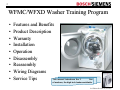
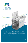
WFMC/WFXD Washer Training
Program
WFMC/WFXD WASHER TRAINING MANUAL
2nd Edition/Revision 0 (4/28/04)
/
2
WFMC/WFXD Washer Training Program
•
•
•
•
•
•
•
•
•
Features and Benefits
Product Description
Warranty
Installation
Operation
Disassembly
Reassembly
Wiring Diagrams
Service Tips
This manual introduces the S line
of washers, the high tech leader worldwide.
2nd Edition/Revision 0 (4/28/04)
/
3
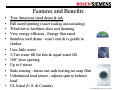
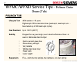
Features and Benefits
•
•
•
•
•
•
•
•
•
•
•
•
True American sized drum & tub
Full sized opening (easier loading and unloading)
Tilted tub to facilitate door seal draining
Very energy efficient - Energy Star rated
Stainless steel drum - won’t rust & is gentle to
clothes
Uses little water
3-Tier water fill for fast & equal water fill
180° door opening
Up to 5 rinses
Suds sensing - rinses out suds leaving no soap film
Unbalanced load sensor - adjusts spin to balance
load
UL listed (U.S. & Canada)
2nd Edition/Revision 0 (4/28/04)
/
4
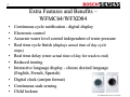
Extra Features and Benefits –
WFMC64/WFXD84
•
•
•
•
Continuous cycle notification - digital display
Electronic control
Accurate water level control independent of water pressure
Real time cycle finish (displays actual time of day cycle
stops)
•
•
•
Real time delay (enter actual time of day for wash to end)
Reduced ironing
Interactive language display - choose desired language
(English, French, Spanish)
• Digital clock (am/pm format)
• Continuous suds sensing
• Child lockout
2nd Edition/Revision 0 (4/28/04)
/
5
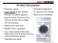
Product Description
• Electronic controls
• Guaranteed temperatures
• Large capacity & door opening
• UL listed (U.S. & Canada)
• Detergent & softener dispenser
• Drain hose & cord holder
• Regular/Cotton, Permanent Press,
Delicates & Hand Wash settings
• 180º door opening
Electronic
controls
Adjustable
spin speeds
• Stainless steel inner drum
• Durable Polinox outer drum
• Power Wash (WFMC32/WFXD52),
Bleach, Rinse Plus & Reduced Ironing
(WFMC64/WFXD84) buttons
Safety
door lock
• Adjustable spin speeds
Accessible drain trap
(for servicers only)
Energy
Star rated
2nd Edition/Revision 0 (4/28/04)
/
6
Warranty
Bosch & Siemens Washers Limited Lifetime Warranty
Statement of Limited Warranty
The warranties provided by BSH Home Appliances ("Bosch“ & “Siemens”) in this
Statement of Warranties apply only to Bosch & Siemens clothes washers sold to the first
using purchaser by Bosch, Siemens or their authorized dealers, retailers or service centers in
the United States or Canada. The Warranties provided herein are not transferable, and take
place from date of installation or ten business days after delivery date, whichever comes
first.
1 Year Full Limited Warranty
Bosch & Siemens will repair or replace, free of charge, any component part that proves
defective under conditions of normal home use, labor and shipping costs included. Warranty
repair service must be performed by an authorized Bosch or Siemens Service Center.
2 Year Limited Warranty
Bosch & Siemens will provide replacement parts, free of charge, for any component part
that proves defective under conditions of normal home use, shipping costs included, labor
charges excluded.
For location of nearest repair depot call 1-800-944-2904 from 5:00 AM - 5:00 PM M-F
(Pacific time)
2nd Edition/Revision 0 (4/28/04)
/
7
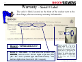
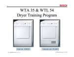
Warranty – Serial # Label
The serial # label, located on the front of the washer next to the
door hinge, shows necessary warranty information.
Serial #
label
• Model # - “WFMC6400UC/01”.
•
Serial # - “FD 8308”. To find when the product type
was built, add 20 to the 1st two digits to get the year
(83 + 20 = 103 ◊ product type was built in 2003). The
last two digits show the month (08 = August).
Factory serial # - Can convert
factory serial # to FD # for
warranty use. 1st 2 digits show
factory # (85 = New Bern), 3rd digit
shows year (1 = 2003), 4th & 5th
digits show month built (08 =
August). So, serial # starting with
“85308…400126” = washer built
@ New Bern with FD 8308
000126.
2nd Edition/Revision 0 (4/28/04)
/
8
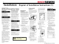
Installation – Reprint of Installation Instructions (1)
NOTE: Be sure to follow all
national & local codes.
2nd Edition/Revision 0 (4/28/04)
/
9
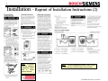
Installation – Reprint of Installation Instructions (2)
HINT: To quickly
remove shipping
(transport) bolts,
use a 13mm
socket wrench.
HINT: To avoid damaging washer, don’t move
it while the feet (leveling legs) are extended.
2nd Edition/Revision 0 (4/28/04)
/
10
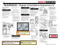
Installation – Reprint of Installation Instructions (3)
HINT:
Cold & hot water
connections are clearly marked
on the rear of the washers.
HINT: To eliminate possibility of leaking,
don’t overtighten fittings.
Teflon tape
can also be used on all threads.
HINT: Be sure to remove the transport
(shipping) bolts & keep them near the
washer (for future shipment).
2nd Edition/Revision 0 (4/28/04)
11
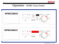
Operation – WFMC Fascia Panels
WFMC32UC
WFMC64UC
2nd Edition/Revision 0 (4/28/04)
12
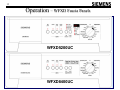
Operation – WFXD Fascia Panels
WFXD5200UC
WFXD8400UC
2nd Edition/Revision 0 (4/28/04)
13
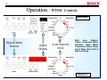
Operation – WFMC Controls
WFMC3200UC
Special Wash
Buttons
Digital
Display
Cycle Selector
Knob
Both
have
Regular/
Cotton, Permanent Press,
Delicates, Hand Wash,
Temperature Boost, Wool,
Active Wear, Rinse Plus &
Bleach settings.
WFMC64UC
2nd Edition/Revision 0 (4/28/04)
14
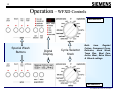
Operation – WFXD Controls
WFXD5200UC
Special Wash
Buttons
Digital
Display
Cycle Selector
Knob
Both
have
Regular/
Cotton, Permanent Press,
Delicates, Hand Wash,
Temp Plus, Wool Care,
Active Wear, Extra Rinse
& Bleach settings.
WFXD8400UC
2nd Edition/Revision 0 (4/28/04)
/
15
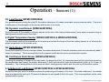
Operation – Sensors (1)
1A. Load Sensor (WFMC32/WFXD52)
At a predefined points during the initial fill, the washer determines if it needs more water using a pressure switch. This is due
to differences in the absorption of the laundry and the size of the loads.
1B. Dynamic Load Sensor (WFMC64/WFXD84)
During the entire fill the washer continually adjusts for the size of the load and determines if more water is needed using an
analog pressure switch and a flow meter.
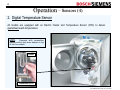
2. Digital Temperature Sensor (WFMC32/WFXD52 & WFMC64/WFXD84)
The thermostat monitors the temperature of the water and controls the length of time the heating element is on, ensuring the
proper temperature for the chosen cycle.
3A. Suds Sensor (WFMC32/WFXD52)
During the beginning of the1st rinse/spin phase, the washer determines if there are excessive suds and automatically adds 2
rinses (if necessary). This is accomplished via the pressure switch and the motor synchronization system.
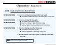
3B. Continuous Suds Sensor (WFMC64/WFXD84)
Checking the pumping out phase of the main wash, the beginning of the 1st rinse/spin phase and the actual spin speed vs.
the programmed spin speed, the washer determines if there are excessive suds and automatically adds up to 2 rinses (if
necessary). This is accomplished via the pressure switch, analog pressure switch and the motor synchronization system.
4. Unbalanced Load Sensor (WFMC32/WFXD52 & WFMC64/WFXD84)
During the final spin cycle the washer monitors the positioning and balance of the load. If the load unbalanced, the washer
stops and adjusts the load up to 15 times and reduces the spin speed to finish the cycle. This is accomplished via the motor
synchronization system.
2nd Edition/Revision 0 (4/28/04)
/
16
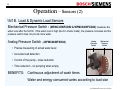
Operation – Sensors (2)
1A/1B. Load & Dynamic Load Sensors
Mechanical Pressure Switch - (WFMC32/WFXD52 & WFMC64/WFXD84) measures the
water level after the first fill. If the water level is high (like for smaller loads), the pressure increases and the
pressure switch does not provide more water.
Analog Pressure Switch - (WFMC64/WFXD84)
• Precise measuring of actual water level
Analog
Pressure
Switch
Mechanical
Pressure
Switch
• Accurate load detection
• Control of the pump - noise reduction
• Time reduction - no pumping when empty
BENEFITS: Continuous adjustment of wash times
Water and energy consumed varies according to load size
2nd Edition/Revision 0 (4/28/04)
/
17
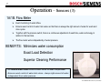
Operation – Sensors (3)
1A/1B. Flow Meter
Exact monitoring of water inflow.
Ensures exact control of water inlet valves so that there is always the right amount of water for wash and
rinse cycles.
Together with the pressure switch, there is a continuous adjustment of wash time, water and energy in
relation to the load size.
The flow meter works independently of water pressure.
BENEFITS: Minimizes water consumption
Exact Load Detection
Superior Cleaning Performance
• An internal water clock monitors water inflow via soak compartment.
• Ensures exact control of water inlet valves - always right amount of water.
• Independent from water pressure.
2nd Edition/Revision 0 (4/28/04)
/
18
Operation – Sensors (4)
2. Digital Temperature Sensor
All models are equipped with an Electric Heater and Temperature Sensor (NTC) to deliver
guaranteed wash temperatures.
NOTE:
Compare with competition
washers which only have heaters in top
of the line models.
Heater
Thermostat (NTC)
2nd Edition/Revision 0 (4/28/04)
/
19
Operation – Sensors (5)
3A/3B. Suds & Continuous Suds Sensors
WFMC64/WFXD84
Detection during draining out after main wash
immediate additional rinse & cancelling of 1st rinse spin
WFMC64/WFXD84
Detection during 1st rinse spin
immediate interuption of spin
insertion of one or two additional rinses
reduced agition during additional anti foam rinse
WFMC32/WFXD52
WFMC64/WFXD84
Detection during any other rinse spin
immediate interuption of spin
reduced agitiation in following rinse cycle
All subsequent rinse spin cycles are always rechecked
for suds
NOTE: Suds build-up usually occur only when way too
much detergent is used with lightly soiled loads.
2nd Edition/Revision 0 (4/28/04)
/
20
Operation – Sensors (6)
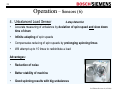
4. Unbalanced Load Sensor
2-step detection
•
Accurate measuring of unbalance by deviation of spin speed and slow down
time of drum
•
Infinite adapting of spin speeds
•
Compensates reducing of spin speeds by prolonging spinning times
•
Will attempt up to 15 times to redistribute a load
Advantages:
•
Reduction of noise
•
Better stability of machine
•
Good spinning results with big unbalances
2nd Edition/Revision 0 (4/28/04)
/
21
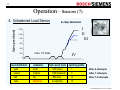
Operation – Sensors (7)
Spin speed [rpm]
4. Unbalanced Load Sensor
2-step detection
I
II
III
1200
1000
800
600
400
200
max. 15 trials
0
load distribution
good
uneven
bad
none
unbalance
small
medium
big
dangerous
Spin speed (rpm)
1200 (max.)
1000 (reduced)
800 (low)
no spinning
IV
spinning profile
I
II
III
IV
After 4 attempts
After 7 attempts
After 14 attempts
2nd Edition/Revision 0 (4/28/04)
/
22
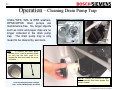
Operation – Cleaning Drain Pump Trap
Unlike WFK, WFL & WFR washers,
WFMC/WFXD drain pumps are
maintenance-free. So, larger objects
such as coins and paper clips are no
longer collected in the drain pump
trap. The drain pump trap is only
meant to be cleared by servicers.
HINT: To remove the drain pump
access cover, insert a pointed object
(or tool) into the hole, push in to
release the latch and rotate the cover
clockwise.
Current production pumps are beige
color – earlier WFMC pumps were black.
NOTE: There’s no provision to drain
water manually from drain pumps like
earlier models.
2nd Edition/Revision 0 (4/28/04)
/
23
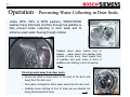
Operation – Preventing Water Collecting in Door Seals
Unlike WFK, WFL & WFR washers, WFMC/WFXD
washers have tilted tubs and flow through tub paddles to
help prevent water collecting in door seals and to
enhance wash water flowing through clothes.
Paddles direct water toward front of
washer – water drains into paddles from
outside of inner drum, flows toward front
of paddles and exits holes in front of
paddles onto clothing in front of washer.
Directing water away from door seals:
• Drums are tilted to direct water to the back of the drum and
away from the door seal.
• Door glass is shaped to direct water away from the door seal.
• Paddles insure clothing at front of dryer get wet despite tub
being tilted toward the back.
2nd Edition/Revision 0 (4/28/04)
/
24
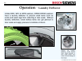
Operation – Laundry Deflector
Unlike WFK, WFL & WFR washers, WFMC/WFXD washers
have a laundry deflector to prevent small items such as
socks and wash rags from collecting in door seals. Without
laundry deflectors, small clothes items can get jammed in
door seals and apply pressure to bottoms of doors.
Without
the
laundry
deflector, small clothes
items being jammed in
door seals would only
cause minimal leakage (a
few drops).
2nd Edition/Revision 0 (4/28/04)
/
25
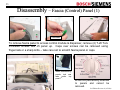
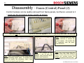
Disassembly – Fascia (Control) Panel (1)
T-20 screws
To remove fascia panel to access control module & dispenser, remove (4) T-20 Torx
front/side screws and lift panel up. Caps over screws can be removed using
fingernails or a sharp knife – take care not to scratch fascia panel or caps.
When reassembling
panels, tuck rear
tabs
under
top
st
panel 1 .
Knobs are permanently attached
to panels and cannot be
removed.
2nd Edition/Revision 0 (4/28/04)
/
26
Disassembly – Fascia (Control) Panel (2)
Control modules can be readily removed from fascia panels, but there’s a knack to it
– must use the procedure below exactly as shown.
Start from left side
Pry outer & inner tabs together L – R
Pry out (3) inner tabs + all outer tabs
HINT: The knob does NOT have
to be removed to remove the
control module. The module lifts
off completely from the panel,
knob & buttons.
HINT: Don’t force modules out from fascia panels
to avoid breaking plastic parts. If modules don’t
come out easily, the procedure hasn’t been
followed and plastic parts will break.
HINT: Don’t remove the wire
holders – clip off wire ties
instead. Carry extra wire ties to
reattach wire harnesses.
NOTE: Some control modules have been
replaced since fault codes stored in
module or motor control can’t be cleared.
Modules are operating properly and
shouldn’t be replaced to clear fault codes.
2nd Edition/Revision 0 (4/28/04)
/
27
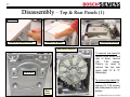
Disassembly – Top & Rear Panels (1)
T-20 screws
Remove top panel screws
Remove top panel
Top panel removed
Rear panel removed
To remove rear panel to
access drive motor and
rear of drum, remove
(18)
T-20
screws.
There’s no need to
remove the top rear
panel (with “H” & “C”
stampings).
T-20 screws
Rear
panel
To remove top panel (for
easier parts access),
remove (3) T-20 screws
and slide panel to rear of
washer.
2nd Edition/Revision 0 (4/28/04)
/
28
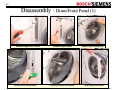
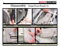
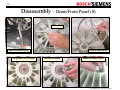
Disassembly – Drum/Front Panel (1)
Remove hinge cover screws
Remove door latch screws
Remove hinge screws
Carefully remove front shield
Remove door seal spring
Removing front shield
2nd Edition/Revision 0 (4/28/04)
/
29
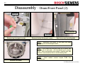
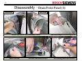
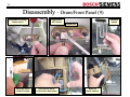
Disassembly – Drum/Front Panel (2)
T-20 screws
Front panel tab
T-20 screws
Remove top front panel screws
Remove bottom front panel screws
Note front panel mounting tabs
Removing front panel at this point will make
removing front counterweights easier.
HINT:
HINT: Front panels are mounted using six (6) plastic tabs
– three (3) on each side. Lift front panels up to remove
them. When reassembling front panels, carefully align tabs
and don’t use excessive force to avoid breaking tabs.
Most
screwdrivers.
HINT:
washer
screws
require
T-20
Torx
Remove front panel
2nd Edition/Revision 0 (4/28/04)
/
30
Disassembly – Drum/Front Panel (3)
Remove door latch
Note door latch manual release
Top counterweight must be removed
13mm screws
Loosen top counterweight screws
Slide out top counterweight
Note top counterweight bushing slots in tub
2nd Edition/Revision 0 (4/28/04)
/
31
Disassembly – Drum/Front Panel (4)
13mm screws
13mm screws
Remove right and left front counterweight screws
Remove door seal
Disconnect main water inlet hose
Note counterweight screw bushings in tub
Disconnecting main water inlet hose
2nd Edition/Revision 0 (4/28/04)
/
32
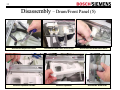
Disassembly – Drum/Front Panel (5)
Disconnect dispenser hoses
Remove dispenser screws
Disconnect water inlet valve hoses
Remove dispenser
Disconnect hot water valve hose
Disconnect drain hose
2nd Edition/Revision 0 (4/28/04)
/
33
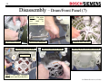
Disassembly – Drum/Front Panel (6)
Disconnect sump hose clamp
Remove drain pump
Disconnect sump hose
Disconnect sump hose clamp
Remove
sump
NOTE: Old style drain pump shown (not used in production)
2nd Edition/Revision 0 (4/28/04)
/
34
Disassembly – Drum/Front Panel (7)
NOTE: Old style
dampers
shown
(not
used
in
production)
Disconnect hoses
Disconnect dampers
Disconnect motor wires
Remove drum drive motor
Remove belt from tub
Showing drum drive motor mounts
10mm bolts
NOTE:
Old style dampers
shown (not used in production)
2nd Edition/Revision 0 (4/28/04)
/
35
Disassembly – Drum/Front Panel (8)
13mm bolt
Remove pulley wheel
Remove tub rear spring
Tub ground wire & washer
Remove tub washer
Remove tub ground wire
2nd Edition/Revision 0 (4/28/04)
/
36
Disassembly – Drum/Front Panel (9)
Disconnect locking
heater wires
Remove
heater
Disconnect
NTC wires
10mm bolt
Unscrew motor
control screws
Disconnect motor
control wire harnesses
Remove
motor control
2nd Edition/Revision 0 (4/28/04)
/
37
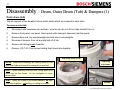
Disassembly – Drum, Outer Drum (Tub) & Dampers (1)
Outer drum (tub)
The tub consists of two durable Polinox plastic shells which are screwed to each other.
To remove outer tub:
1.
Disconnect wire harnesses (as needed) – wire ties can be cut off, but clips shouldn’t be cut.
2.
Remove front panel, rear panel, fascia panel (with detergent dispenser) and top panel.
3.
Remove door seal, top counterweight and both side counterweights.
4.
Disconnect dampers from tub and slip belt off of tub.
5.
Remove tub through rear of washer.
6.
Remove (18) T-25 Torx screws holding front & rear tubs together.
T-25 screws
Removing front of tub
NOTE: Rear drum bearings are factory press fit into
rear outer tubs and cannot be removed or serviced.
Removing
tub screws
HINT: When installing outer tub bolts, screw them in by
hand onto the first thread.
thread them.
Do not overtighten or cross-
HINT: Unlike WFL2060 & WFR2460 washers, no clips
hold tubs together – no drilling or cutting is needed.
Damper
2nd Edition/Revision 0 (4/28/04)
/
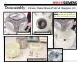
38
Disassembly – Drum, Outer Drum (Tub) & Dampers (2)
Rear drum bearings are
factory press fit into rear outer tubs
and cannot be removed or serviced.
NOTE:
Lift drum out of tub
Bearing and drum shaft
Showing drum and tub parts
2nd Edition/Revision 0 (4/28/04)
/
39
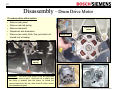
Disassembly – Drum Drive Motor
To remove drum drive motors:
• Remove rear panel
• Remove rear tub spring
Drum drive
motor
• Remove drum belt
• Disconnect wire harnesses
• Remove two motor bolts, then pull motor out
toward rear of washer
10mm bolts
Rear tub
spring
WARNING: The drum drive motor & tub are grounded
through the motor control. Since the tub is plastic and
the motor is isolated from the frame, Its critical the
ground leads from the tub, drive motor & motor control
are connected properly.
2nd Edition/Revision 0 (4/28/04)
/
40
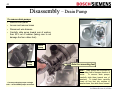
Disassembly – Drain Pump
To remove drain pumps:
• Remove front panel
• Loosen and remove hoses
• Disconnect wire harness
• Carefully slide pump toward rear of washer,
then lift it out of washer (taking care to not
damage the four rubber feet).
Drain
pump
Drain
pump
Current production pumps are beige
color – earlier WFMC pumps were black.
Note four mounting feet
HINT: Drain pumps are mounted on
four rubber feet to dampen vibration &
noise.
To remove drain pumps,
carefully slide them toward rear of
washers. To install them, carefully
insert all four feet into notches in
washer base, then slide them forward.
2nd Edition/Revision 0 (4/28/04)
/
41
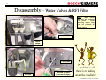
Disassembly – Water Valves & RFI Filter
HINT:
Water valves
are bent and snapped
into place.
When
removing valves, take
care not to break off
plastic pieces.
Hot water valve
Water
valves
T-20 screws
RFI filter
Unscrew RFI filter
(from rear of dryer)
…and that’s all
there is to taking
apart the washers!
2nd Edition/Revision 0 (4/28/04)
/
42
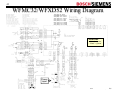
WFMC32/WFXD52 Wiring Diagram
10ºC (50ºF): 36 – 44kW
20ºC (68ºF): 22.8 – 27.4kW
30ºC (86ºF): 14.8 – 17.5kW
40ºC (104ºF): 9.8 – 11.5kW
50ºC (122ºF): 6.6 – 7.7kW
60ºC (140ºF): 4.6 – 5.3kW
66ºC (151ºF): 3.73 – 4.29kW
73ºC (163ºF): 2.94 – 3.36kW
86ºC (187ºF): 1.93 – 2.19kW
DEFINITIONS:
• “Mains” = “power”
• “Earth” = “ground”
Power
input
2nd Edition/Revision 0 (4/28/04)
/
43
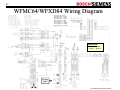
WFMC64/WFXD84 Wiring Diagram
10ºC (50ºF): 36 – 44kW
20ºC (68ºF): 22.8 – 27.4kW
30ºC (86ºF): 14.8 – 17.5kW
40ºC (104ºF): 9.8 – 11.5kW
50ºC (122ºF): 6.6 – 7.7kW
60ºC (140ºF): 4.6 – 5.3kW
66ºC (151ºF): 3.73 – 4.29kW
73ºC (163ºF): 2.94 – 3.36kW
86ºC (187ºF): 1.93 – 2.19kW
DEFINITIONS:
• “Mains” = “power”
• “Earth” = “ground”
Power
input
2nd Edition/Revision 0 (4/28/04)
44
/
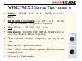
WFMC/WFXD Service Tips – Ratings (1)
• Ratings: 120VAC, 15A, 60 Hz, 1350W (uses 11A
max.).
• Hot & cold water inputs: 3/4” NPT, 14.5 – 145 psi,
2.2 gal. (8 l)/minute – 5.2 gal (19.8 l)/minute.
• Plug: NEMA 5-15P 120V, 15A, 3-wire.
• Spin speeds: 400-1000 RPM (WFMC32/WFXD52) or
400-1200 RPM (WFMC64/WXFD84).
• Three concrete vibration dampeners, one top & two
front.
• Drum has five – point suspension.
• Uses Polinox outer drum - quieter & dent resistant
compared to ss.
• UL listed (U.S. & Canada).
2nd Edition/Revision 0 (4/28/04)
45
/
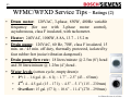
WFMC/WFXD Service Tips – Ratings (2)
• Drum motor: 120VAC, 3-phase, 850W, 400Hz variable
frequency (for use with 3-phase motor control),
asynchronous, class F insulated, with tachometer.
• Heater: 240VAC, 1000W, 8.8A, 13.7 – 15.2 W.
• Drain pump: 120VAC, 60 Hz, 70W, class F insulated, 15
min. on / 45 min. off duty, thermally protected, isolated by
four rubber feet (noise/vibration dampened).
• Drain pump flow rate: 18 liters/minute @ 2.5m (8’) head
and 30 liters/minute @ 1.25m (4’) head .
• Water levels (cotton cycle, empty drum):
• 1st: 1 – 1.6 gal. (4 – 6 l); ~ 1.7” – 2.5” (43 – 65mm)
• 2nd: 4 – 4.5 gal. (15 – 17 l); ~ 4.5” – 5.1” (115 – 230mm)
• Overflow: 15 gal. (57 l); ~ 10.6” – 11.4” (270 – 290mm)
2nd Edition/Revision 0 (4/28/04)
/
46
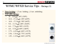
WFMC/WFXD Service Tips – Ratings (3)
• Door locking: ≤ 2 sec. locking, ≤ 4 sec. unlocking.
• NTC (R1) ratings:
• 36 – 44 kW@ 10ºC (50ºF)
• 22.8 – 27.4 kW@ 20ºC (68ºF)
• 14.8 – 17.5 kW@ 30ºC (86ºF)
• 9.8 – 11.5 kW@ 40ºC (104ºF)
• 6.6 – 7.7 kW@ 50ºC (122ºF)
• 4.6 – 5.3 kW@ 60ºC (140ºF)
• 3.73 – 4.29 kW@ 66ºC (151ºF)
• 2.94 – 3.36 kW@ 73ºC (163ºF)
• 1.93 – 2.19 kW@ 86ºC (187ºF)
2nd Edition/Revision 0 (4/28/04)
/
47
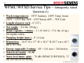
WFMC/WFXD Service Tips – Infrequently Asked
Questions (1)
• Wash temperatures: 155ºF Sanitary, 150ºF Temp. boost,
120ºF – 125ºF Hot, 90ºF – 95ºF Warm, 60ºF – 70ºF Cold.
• Length of power cord – 6’ (72”)
• Net weight – 216 lbs. (98 kg.)
• Drum capacity / volume – 3.1 ft3 (88 l) / 17.6 lbs. (8 kg.)
for regular cotton
• Pumping height (max.) – 8’ (2.4 m)
• Dimensions – 36.9” H x 27” W x 30.2” D (93.7 cm x 68.7
cm x 76.7 cm)
• Energy (appendix J rating) – EF > 4.0; uses < 284 kwh/yr.
• Noise level (wash) – 60 dB
• Noise level (max. spin) – 70 dB (WFMC32/WFXD52); 72
dB (WFMC64/WFXD84)
2nd Edition/Revision 0 (4/28/04)
/
48
WFMC/WFXD Service Tips – Infrequently Asked
Questions (2)
• Door opening – 16” (41 cm)
• Water usage / ft3 – 8.5 gal./ft3 (WFMC32/WFXD52); 7.5
gal./ft3 (WFMC64/WFXD84)
• Water usage:
• WFMC32/WFXD52
• Cotton (temp boost; 4.4 lbs.) – 13.7 gal. (52 l)
• Cotton (cold; 13.2 lbs.) – 20 gal. (75 l)
• Permanent Press (warm; 8.8 lbs.) – 14.5 gal. (55 l)
• Hand Wash (6.6 lbs.) – 8.5 gal. (32 l)
• WFMC64/WFXD84
• Cotton (temp boost; 4.4 lbs.) – 13.2 gal. (50 l)
• Cotton (cold; 13.2 lbs.) – 20 gal. (75 l)
• Permanent Press (warm; 8.8 lbs.) – 14 gal. (53 l)
• Hand Wash (6.6 lbs.) – 10.5 gal. (40 l)
2nd Edition/Revision 0 (4/28/04)
/
49
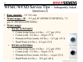
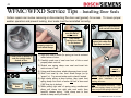
WFMC/WFXD Service Tips – Installing Door Seals
Certain repairs can involve removing or disconnecting the door seal (gasket) for access. To insure proper
washer operation and prevent leaking, door seals must be reinstalled correctly.
Make sure clamp doesn’t
pull seal off front shield
Place spring clamp
over left half of
seal in notch
Make sure seal is
properly seated on
front shield flange
Center notch in bottom of
seal (for spring) under
bottom of door
Dispenser
hose
Inner
spring
Keep clamp
spring over notch
at seal bottom
To install door seals:
1) Align door seal so notch (for spring) at front is centered
under bottom of door.
2) Carefully push rear of seal over front of tub so seal
properly seats onto tub.
3) Stretch rear spring clamp over seal and insert into
notch at rear of seal.
4) Using small hose clamp, attach dispenser hose to seal.
5) Work front seal lip over front shield flange (so lip
“snaps” in). Tug around entire seal to check if seated.
6) Align clamp spring at door bottom, then insert front
spring clamp into notch of entire left half of door seal
(180º from top to bottom).
7) While pulling right side of spring using needlenosed
pliers, pull clamp into right side seal notch, then
carefully release spring. Hold clamp next to front
shield so clamp won’t pull seal off.
Carefully pull spring to
right & put clamp into
right side seal notch
Hold clamp
next to
front shield
NOTE: Check to make sure seal is
seated after installation so no
leaking will occur.
TIP: Left-handed servicers -- start
the front spring clamp on the right
side and pull the spring to the left.
2nd Edition/Revision 0 (4/28/04)
/
50
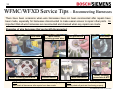
WFMC/WFXD Service Tips – Reconnecting Harnesses
There have been occasions when wire harnesses have not been reconnected after repairs have
been made, especially for harnesses disconnected to make easier access to repair other parts. Its
important that all wire harnesses are reconnected and checked when any repairs are made.
Examples of wire harnesses that can be left disconnected:
Door latch
Motor, including ground wires
Motor control,
including ground wires
Pressure switch
HINT: Write down all harnesses disconnected during repairs,
then check all harnesses after repairs have been made.
Tub ground wire
Water inlet valves
Drain pump
Heater, including
ground wire & NTC
HINT: If needed, run test P:3 (P:03) and
visually check all parts are functioning properly.
2nd Edition/Revision 0 (4/28/04)
/
51
WFMC/WFXD Service Tips – Drum Drive Motor
Motor control (on
left side viewing
rear of washer)
Drum motor
resistances:
Unlike previous washers, drum
drive motors are 3-phase & are
controlled by separate motor
controls mounted on the base near
the motors (in the right rear of
washers). These controls provide
motor power & speed control.
3
connections
Speed tachometer connections
WARNING: The drum drive motor & tub are grounded through the motor control.
Since the tub is plastic and the motor is isolated from the frame, Its critical the
ground leads from the tub, drive motor & motor control are connected properly.
Speed sensor
3 Motor control
NOTE: Motor is rated @ 120VAC, 3-phase, 850W, 400Hz variable frequency.
2nd Edition/Revision 0 (4/28/04)
/
52
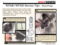
WFMC/WFXD Service Tips – Drain Pump
Drain pumps reliably pump water out from washer
tubs through the drain reservoir and drain hose.
Unlike earlier washers, these pumps are
maintenance free -- access to remove debris is
only meant for servicers.
NOTE: Drain pump motor resistance ranges from
140 – 200 . Its rated @ 120VAC, 60 Hz, 70W.
HINT: To remove the drain pump access cover,
insert a pointed object (or tool) into the hole, push in
to release the latch and rotate the cover clockwise.
HINT: Drain pumps are mounted on four rubber
feet to dampen vibration & noise. To remove
drain pumps, carefully slide them toward rear of
washers. To install them, carefully insert all four
feet into notches in washer base, then slide
them forward.
NOTE: There’s no provision for draining residual water from drain pumps.
Current production pumps are beige
color – earlier WFMC pumps were black.
2nd Edition/Revision 0 (4/28/04)
/
53
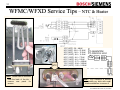
WFMC/WFXD Service Tips – NTC & Heater
NTC
HINT: Heater can be removed
from the back of the tub –
remove rear panel for
access.
10ºC (50ºF): 36 – 44kW
20ºC (68ºF): 22.8 – 27.4kW
30ºC (86ºF): 14.8 – 17.5kW
40ºC (104ºF): 9.8 – 11.5kW
50ºC (122ºF): 6.6 – 7.7kW
60ºC (140ºF): 4.6 – 5.3kW
66ºC (151ºF): 3.73 – 4.29kW
73ºC (163ºF): 2.94 – 3.36kW
86ºC (187ºF): 1.93 – 2.19kW
HINT: NTC connector is latched
– carefully pry latch with small
blade screwdriver to remove it.
2nd Edition/Revision 0 (4/28/04)
/
54
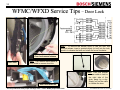
WFMC/WFXD Service Tips – Door Lock
HINT: To remove the access cover to use the door lock
manual release, insert a pointed object (or tool) into the hole,
push in to release the latch and rotate the cover clockwise.
Door lock manual release
Door lock
HINT: Can remove fascia panel &
front shield to access door lock.
Door lock terminals
Current production drain pumps are beige color – earlier WFMC pumps were black.
HINT: Door lock manual
release cable is held to
the right side of the
drain pump by a clip.
Simply pull on the cable
to release the door.
2nd Edition/Revision 0 (4/28/04)
/
55
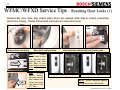
WFMC/WFXD Service Tips – Resetting Door Locks (1)
Occasionally door locks stay locked when doors are opened while they’re locked, preventing
doors from closing. Please follow these instructions to reset door locks.
Rear
view
Remove front seal spring
Move door seal for access
Push onto back of door lock until it clicks open
HINT:
Reach
around back of door
lock (opposite latch
opening) and push
onto back of lock
plate (directly behind
latch) until it clicks.
Push
Pull
HINT:
If lock
doesn’t release,
pull green manual
door release cord
(down) and push
onto back of lock
a 2nd time.
Door lock latched
Door lock open
NOTE: Advise customers against
pulling doors open while locked.
2nd Edition/Revision 0 (4/28/04)
/
56
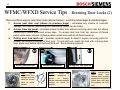
WFMC/WFXD Service Tips – Resetting Door Locks (2)
There are three ways to reset door locks (shown below) – each has advantages & disadvantages:
1.
2.
3.
Access past door seal (shown on previous page) – eliminates any chance of cosmetic
damage, but requires reattaching door seal spring (which can be tricky).
Access from top panel – provides access to door lock without removing door seal, but allows
scratching of fascia panel and screw caps. To access door lock from top, remove (4) fascia
panel screw caps, remove (4) fascia panel screws and carefully lift fascia panel up.
Pulling door lock latch out – provides quickest repair & doesn’t require removing parts for
access, but allows scratching of door lock. To pull latch out, reach into lock with a strong steel
loop, place loop behind latch and pull latch out. Some force is required.
Access past door seal
HINT:
Tub is
suspended from
springs and can
easily be moved
back for better
access.
Access from top panel
NOTE:
Doors can
become misaligned if
leaned
on
heavily.
Advise customers against
leaning on doors for
support.
Pulling door lock latch out
HINT: Locked doors
open
when
door
latches aren’t properly
seated into door locks.
Adjust door until latch
fits properly into door
lock.
2nd Edition/Revision 0 (4/28/04)
/
57
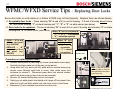
WFMC/WFXD Service Tips – Replacing Door Locks
Some door locks on units made on or before 2/13/04 may not hold properly. Replace them (as shown below):
1. Acceptable door locks – Those showing “N” at end of # on end of housing. If # end of housing doesn’t show
“N”, then those showing “1” on black housing and “1”, “2” or “3” on white carrier (see below).
2. Door locks to be replaced – Those not showing “N” at end of # on end of housing and showing “2” on black
housing and “4” on white carrier (see below).
When “N” isn’t on end panel #:
• “1”, “2” or “3” -- is acceptable
• “4” -- should be replaced
• GOOD -- “N” at end
of # on end panel
(e.g. 502042N)
• REPLACE -- “N”
not at end of # on
end panel (e.g.
350031C)
Front view
Rear view
When “N” isn’t
on end panel #:
• “1”
-is
acceptable
• “2” -- should
be replaced
Procedure on replacing door locks:
1. Remove fascia panel by removing (4) screws (and plastic screw caps).
Carefully lay fascia panel out of the way (on top panel).
2. Using a thin tool (e.g. awl or drill bit), push latch on circular drain pump
access cover (through small hole in cover), then rotate cover (cw)
clockwise to remove it. Disconnect green door lock manual release
cable from drain pump (so door lock can be removed).
3. Remove (2) screws holding door lock to front panel.
4. Gently pry out white plastic front shield until it pops off front panel, then
slide lock to left until black plastic lock rails clear notch in front frame.
5. Disconnect (3) wire harness connectors from door lock.
Access cover
hole
White
plastic
front
shield
rails
HINT: Door lock manual
release cable is held to
the right side of the drain
pump by a clip.
Notch in
front frame
2nd Edition/Revision 0 (4/28/04)
/
58
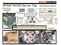
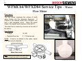
WFMC64/WFXD84 Service Tips – Water
Flow Meter
Flow sensor
The flow sensor measures the volume of (cold)
water flowing into the detergent dispenser.
It
consists of an impeller wheel with a magnet core
and a Hall integrated circuit. When the wheel
rotates, the magnet emits impulses to the Hall IC.
Water flow
Cold
Cold
The water flow is marked by an arrow on the side of
the sensor.
Hot
Specifications:
• Voltage:
12 VDC
• Detected flow rate:
0 – 10 liters/minute
NOTE: If there’s air bubbles in the water, higher
flow rates may be detected.
Water flow arrow
HINT: Make sure the water flow arrow points
from the water inlet valve to the dispenser.
2nd Edition/Revision 0 (4/28/04)
/
59
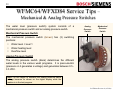
WFMC64/WFXD84 Service Tips –
Mechanical & Analog Pressure Switches
The water level (pressure switch) system consists of a
mechanical pressure switch and an analog pressure switch.
Analog
Pressure
Switch
Mechanical
Pressure
Switch
Mechanical Pressure Switch
The mechanical pressure switch (brown) has (3) switching
positions:
•
•
•
Water level < level 1
Water heating level
Overflow level
Analog Pressure Switch
The analog pressure switch (black) determines the different
water levels in the various wash programs. It is piezo-electric
(pressure on it generates a voltage) and generates between 0.5 3.5 VDC.
HINT: Its not helpful to measure the analog pressure switch
voltage because its shown on the digital display while the
washer is in the test program.
2nd Edition/Revision 0 (4/28/04)
/
60
WFMC/WFXD Service Tips – Polinox Outer
Drum (Tub)
POLINOX TUB
Lifecycle Test
4000 washes = 10 years
Highest spin 300 consecutive times (wash-spin, wash-spin, etc. have tested up to 900 wash-spin cycles)
Heat Resistant Up to 130°C (266°F)
Stability
Dropped from a great height, won’t dent like Stainless Steel – is
used on Mercedes-Benz bumper
•
•
•
•
•
•
Suspension
Reinforced with glass fiber
Extraordinary strength
Very reliable
Vibrates less/ less noisy
Fewer parts
Lower weight
Five – point (two top springs, two dampers, one rear spring)
2nd Edition/Revision 0 (4/28/04)
/
61
WFMC32/WFXD52 Service Tips – Control
Module Wire & Terminal Colors
To water
valves
To drain
pump
BL
WH
2-BL
WH
2-BL
5-BK
WH
To motor
control
IMPORTANT:
Its
possible to miswire the
WH,
YE
&
GN
terminals. Make sure
the terminals are in the
right order & direction
(wires on left side).
WH
BL
clear
6-WH
120V input
HINT: This
will help with
reconnecting
wires.
To heater
PK
YE
2-PK
To
pressure
switch
GN
7-BL
WH
To
door
lock
Remove cover to access wires
2nd Edition/Revision 0 (4/28/04)
/
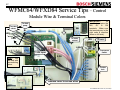
62
WFMC64/WFXD84 Service Tips – Control
Module Wire & Terminal Colors
To water
valves
To drain
pump
WH
BL
2-BL
2-BL
WH
To motor
control
5-BK
4-WH
PK
WH
To heater
GY
YE
120V input
HINT: This
will help with
reconnecting
wires.
IMPORTANT:
Its
possible to miswire the
WH,
GY
&
GN
terminals. Make sure
the terminals are in the
right order & direction
(wires on left side).
To pressure
switch
GN
2-PK
7-BL
WH
To door
lock
Remove cover to access wires
2nd Edition/Revision 0 (4/28/04)
/
63
WFMC/WFXD Service Tips – Test Program
(1A): Starting WFMC32/WFXD52 Test Program
The WFMC32/WFXD52 washer test programs self-diagnose problems, including listing the last 8
fault codes from the control module & the last 16 fault codes from the motor control. The tests are
easy to use, speeding up and simplifying diagnosing washer issues.
P:01
WFMC32
NOTE: Door locks
for all water fill and
drain tests.
HINT:
If
Start/Pause
light
doesn’t come on for
some tests, door is
open.
Turn off
washer, then close
door.
Entering & using WFMC32/WFXD52 test programs:
• To reset, rotate cycle selector knob to Off position.
• To enter test program, push and hold Spin Selection and Delay Start buttons at the same time,
then rotate cycle selector knob ccw to Permanent Press Cold position. Hold Spin Selection
and Delay Start buttons until P:01 shows in display.
• To select tests, push Spin Selection button (to scroll through tests) until desired test shows in
display (P:01 - P:17) - Start/Pause light will flash.
• To start tests, push Start/Pause button while its light is flashing -- light stays lit when test has
started. To end tests, push Spin Selection button.
• To exit test program, rotate cycle selector knob to Off position.
2nd Edition/Revision 0 (4/28/04)
/
64
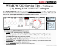
WFMC/WFXD Service Tips – Test Program
(1B): Starting WFMC64/WFXD84 Test Program
The WFMC64/WFXD84 washer test programs self-diagnose problems, including listing the last 8
fault codes from the control module & the last 16 fault codes from the motor control. The tests are
easy to use, speeding up and simplifying diagnosing washer issues.
P1:ERRORS
WFMC64
NOTE: Door locks
for all water fill and
drain tests.
HINT:
If
Start/Pause
light
doesn’t come on for
some tests, door is
open.
Turn off
washer, then close
door.
Entering & using WFMC64/WFXD84 test programs:
• To reset, rotate cycle selector knob to Off position.
• To enter test program, push and hold Menu and Select buttons at the same time, then rotate cycle
selector knob ccw to Permanent Press Cold position. Hold Menu and Select buttons until P1:
Errors shows in display.
• To select tests, push Menu button (to scroll through tests) until desired test shows in display (P1 P17) - Start/Pause light will flash.
• To start tests, push Start/Pause button while its light is flashing -- light stays lit when test has
started. To end tests, push Menu button.
• To exit test program, rotate cycle selector knob to Off position.
2nd Edition/Revision 0 (4/28/04)
/
65
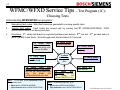
WFMC/WFXD Service Tips – Test Program (1C):
Choosing Tests
Understanding WFMC/WFXD test programs:
1.
Generating fault codes: Most fault codes are generated by running specific tests.
2.
Viewing fault codes: Fault codes are viewed only by running test P1 (WFMC64/WFXD84) / P:01
(WFMC32/WFXD52), not during each test.
3.
Procedure: 1st - select test based on expected problems (see below). 2nd - run test. 3rd - go back and run
test P1 (P:01) to see faults. Scroll through each fault and check if it occurred.
To
check
door
latch:
Fault codes
To check motor:
Run test P4 (P:04)
To check motor
control: Run test
generated during wash
– run test P1 (P:01)
P4 (P:04)
To check
fault codes:
To check drain
pump: Run test
P15, P9 (P:09)
To
check
water
inlet
(pressure switch, flow meter):
Run test P8 (WFMC64/WFXD84
only),
P9
(P:09),
P11
(WFMC64/WFXD84 only), P13
HINT: To run tests, push Start/Pause button.
To end tests, push:
• Menu button (WFMC64/WFXD84)
• Spin Selection button (WFMC32/WFXD52)
To check heater:
Run test P16
Run test P:1
(P01)
To check NTC:
Run test P16
To
check
wire
harnesses: Run test
P4
(P:04),
P8
(WFMC64/WFXD84 only)
HINT: To scroll through tests, push:
• Menu button (WFMC64/WFXD84)
• Spin Selection button (WFMC32/WFXD52)
2nd Edition/Revision 0 (4/28/04)
/
66
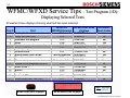
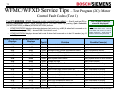
WFMC/WFXD Service Tips – Test Program (1D):
Displaying Selected Tests
All washers have displays showing what test has been selected.
WFMC32/
WFMC64/WFXD84 Generates
Test #
Test
WFXD52 Displays
Displays
Fault Codes
1
2
3
4
5
6
7
8
9
11
12
13
14
15
16
17
Display fault codes
Safety test (don't run)
Automatic test program
Motor
Model coding (variations) - don't run
Displays & lights
Selector knob
Analog water level sensor
Pressure switch
Flow meter
Update control programming (N/A)
Water valve 1
Buzzer
Pump
Heater & NTC
Noise (factory test - don't run)
P:01
P:02
P:03
P:04
P:05
P:06
P:07
Test not available
P:09
Test not available
P:12
P:13
P:14
P:15
P:16
P:17
P1:ERRORS
P2:SAFETY
P3:AUTOM
P4:MOTOR
P5:VARIANT
P6:DISPLAY
P7:SELECTOR
P8:NIVEAU1
P9:NIVEAU2
P11:FLOW
P12:UPDATE
P13:VALVE1
P14:BUZZER
P15:PUMP
P16:HEATER
P17:NOISE
P:03
WFMC32/WFXD52 Displays
No
No
No
Yes
No
No
No
Yes
Yes
Yes
No
Yes
No
Yes
Yes
No
HINT: Skip tests
2, 5, 12 & 17.
WFMC64/WFXD84 Displays
2nd Edition/Revision 0 (4/28/04)
/
67
WFMC/WFXD Service Tips – Test Program (1E):
WFMC64/WXFD84 Text Displays
WFMC64/WFXD84 washers have full text displays showing which devices are running at each
point during each test. They’re helpful for visually determining whether washers are properly
filling, draining & spinning.
Numeral Displayed letter
0
P
NOTE: “
” = drum speed (RPM) &
“n” = pressure switch reading.
HINT: Using the test program can cut
down repair times & eliminate repeat calls
from misdiagnosing problems.
Component/Function
1
2
3
4
5
6
7
8
9
D
M
P
H
V
1
2
3
N0
Door
Motor
Pump
Heater
Valve
Cold water valve (1) - part of dual valve
Cold water valve (2) - part of dual valve
Hot water valve (3)
No water -- below heating water level
9
NH
Heating water level (min. to heat)
9
ND
Door water level (reached door)
10
11
12
12
……
Component actuated
Component not actuated
Clockwise rotation (cw)
Counterclockwise rotation (ccw)
HINT: If Start/Pause light doesn’t come
on for some tests, door is open. Turn off
washer, then close door.
2nd Edition/Revision 0 (4/28/04)
/
68
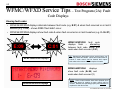
WFMC/WFXD Service Tips – Test Program (2A): Fault
Code Displays
Viewing fault codes:
• WFMC32/WFXD52 displays alternate between fault code (e.g. E:01) & when fault occurred on in last 8
washes (e.g. C:00) – shows C:00 if fault didn’t occur.
• WFMC64/WFXD84 displays show fault code & when fault occurred on in last 8 washes (e.g. 0 - Er:01).
E:09
C:01
WFMC32/WFXD52 Displays
WFMC32/WFXD52 fault code
displays flash – alternating
between fault code (E:09) and
wash when fault occurred (C:01)
TIP: Washers are designed to give a service history, not
show only latest fault codes. Since fault codes stored in
module or motor control can’t be cleared, don’t expect
fault codes to be reset to “0” when repairs are made.
WFMC64/WFXD84
displays
show fault code (Er:09) and
wash when fault occurred (1)
WFMC64/WFXD84 Displays
NOTE: Some control modules have been replaced since
fault codes stored in module or motor control can’t be
cleared. Modules are operating properly and shouldn’t be
replaced to clear fault codes.
2nd Edition/Revision 0 (4/28/04)
/
69
WFMC/WFXD Service Tips – Test Program (2B):
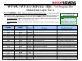
Module Fault Codes (Test 1)
Test P1:ERRORS / P:01 (Viewing control module fault codes) --
Start & end test P1
(WFMC64/WFXD84) / (P:01) (WFMC32/WFXD52) by pushing Start/Pause button. Scroll through list of
fault codes by pushing Spin Selection (WFMC32/WFXD52) or Menu (WFMC64/WFXD84) buttons.
•
WFMC32/WFXD52 displays alternate between fault code (e.g. E:01) & when fault occurred on in
last 8 washes (e.g. C:00) – shows C:00 if fault didn’t occur.
•
WFMC64/WFXD84 displays show fault code & when fault occurred on in last 8 washes (e.g. 0 Er:01).
WFMC32/WFXD52 WFMC64/WFXD84
Displays
Displays
E:01
E:02
E:03
E:04
E:05
E:06
E:07
E:08
E:09
--------E:12
E:13
E:14
--------E:20
E:21
E:22
E:24
Er:01
Er:02
Er:03
Er:04
Er:05
Er:06
Er:07
Er:08
Er:09
Er:10
Er:11
Er:12
Er:13
Er:14
Er:15
Er:16
Er:20
Er:21
Er:22
Er:24
Test #
Problem
Door open
Door lock doesn't unlock
Door lock doesn't lock
Door control broken
NTC open-circuited
NTC shorted
Unexpected heating (heater on at wrong time)
Heater doesn't shut off
Communication lost to motor
Flow meter gives wrong values
No water flow (within 6 minutes)
Water supply time exceeded
Drain pump time exceeded
Overflow level exceeded
Pressure sensor gives failure voltage level
Can't calibrate pressure sensor
Spinning aborted due to unbalanced load
Excessive foam
washing Frequency synchronization failed
Motor power relay failed
P:4
washing
washing
washing
washing
P:16
P:16
P:16
P:16
P:4
P:11
P:8/9/13
P:8/9/13
P:15
P:9
P:8
P:8
P:4
NOTE: Fault codes stored in module can’t be cleared .
Last 8 fault codes are
stored & displayed!
HINT: # of faults reads “0” for
faults which didn’t occur. Look at
# of faults, not error #, to see if
faults occurred -- scroll thru all
faults to check if any occurred.
Possible Cause(s)
Door lock not engaged
Jammed lock or bad wire harness
Jammed lock or bad wire harness
Faulty Triac or control module
Faulty NTC or bad wire harness
Faulty NTC or bad wire harness
Faulty heater or stuck heater relay
Faulty heater or stuck heater relay
Faulty wire harness
Faulty flow meter or wire harness
Faulty inlet valve, wire harness, hose
Faulty inlet valve, wire harness, hose
Faulty drain pump, wire harness, hose
Faulty/blocked pump, hose, inlet valve
Faulty pressure sensor, wire harness
Faulty pressure sensor, wire harness
Unbalanced load or faulty wire harness
Wrong or too much detergent used
Faulty control module
Faulty control module
2nd Edition/Revision 0 (4/28/04)
/
70
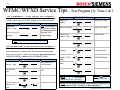
WFMC/WFXD Service Tips – Test Program (2C): Motor
Control Fault Codes (Test 1)
Test P1:ERRORS / P:01 (Viewing motor control fault codes) --
Start & end test P1 by
pushing Start/Pause button. Scroll through list of (18) fault codes by pushing Spin Selection
(WFMC32/WFXD52) or Menu (WFMC64/WFXD84) buttons.
•
WFMC32/WFXD52 displays alternates between fault code (e.g. d:01) & when fault occurred on in
last 16 washes (e.g. C:00) – shows C:00 if fault didn’t occur.
•
WFMC64/WFXD84 displays shows fault code & when fault occurred on in last 16 washes (e.g. 0
- dr:01).
WFMC32/WFXD52 WFMC64/WFXD84
Displays
Displays
Test #
Problem
Last 16 fault codes are
stored & displayed!
HINT: # of faults reads “0” for
faults which didn’t occur. Look at
# of faults, not error #, to see if
faults occurred -- scroll thru all
faults to check if any occurred.
Possible Cause(s)
d:01
dr:01
P:04
Motor control short circuited.
Faulty motor control.
d:02
dr:02
P:04
Motor control interruption.
Faulty motor control.
d:03
dr:03
P:04
Damaged motor control temperature sensor.
Faulty temperature sensor.
d:06
dr:06
P:04
Motor control NTC relay failure.
NTC too hot or relay stuck closed.
d:07
dr:07
P:04
Motor control (inverter) failed or motor shorted. Faulty motor control or motor.
d:08
dr:08
P:04
Motor speed sensor failed.
Faulty speed sensor or wire harness.
d:09
dr:09
P:04
Voltage too high.
Faulty motor control.
d:10
dr:10
P:04
Power limiter switch off.
Motor overloaded or binding.
d:11
dr:11
P:04
Voltage too low.
Faulty motor control.
d:12
dr:12
P:04
Motor control high current switch off.
Motor overloaded or binding.
d:13
dr:13
P:04
Motor control high temperature switch off.
Motor overloaded or binding.
d:14
dr:14
P:04
Motor control high temperature warning.
Motor overloaded or binding.
d:15
dr:15
P:04
Power limiter warning.
Motor overloaded or binding.
d:16
dr:16
P:04
Motor high temperature switch off.
Motor overloaded or binding.
d:17
dr:17
P:04
Motor high temperature warning.
Motor overloaded or binding.
d:18
dr:18
P:04
Peak voltage too high.
Faulty motor control.
NOTE: Fault codes stored in motor control can’t be cleared .
2nd Edition/Revision 0 (4/28/04)
/
71
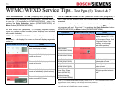
WFMC/WFXD Service Tips – Test Program (3): Tests 2 & 3
Test P2:SAFETY / P:02 (Safety test program) -Skip this European test. Test ends on its own - stop it by pushing the Spin
Selection button (WFMC32/WFXD52) or Menu button (WFMC64/WFXD84).
Operation
Starts filling
(valve 2 - cold)
WFMC64/WFXD84 Display
D M P H
V
1 2 3 NH
n 075
Starts heating (30 D M P H
1 2 3 N
H
V
seconds)
n 075
Notes
HINT: Do not use
this test as it applies
to European models
requiring VDE
safety testing.
NOTE: ‘“n” = pressure switch (analog sensor) reading.
Test P3:AUTOM / P:03 (Automatic test program) -Test 3 turns on motor (wash & spin), heater, drain pump and water
valves separately for a visual check. No fault codes are generated.
Test 3 ends on its own - stop it by pushing the Spin Selection button
(WFMC32/WFXD52) or Menu button (WFMC64/WFXD84).
Operation
Starts filling
(valve 2 - cold)
WFMC64/WFXD84 Display
D M P H
t23
D M P H
Starts heating
D M P H
t23
Starts 2nd fill
(valves 1 & 2 cold)
level (no water)
V
1 2 3 N
H
0000
V
Filling using valve 2 cold
1 2 3 NH Stops valve 2 filling
0000
D M P H
t23
1 2 3 N0 Water starts at N0
0000
Fills up to NH
level
t23
V
Notes
V
0000
1 2 3 N
H
Keeps heating
Operation
Starts ccw
rotation
WFMC64/WFXD84 Display
D M P H
t23
D M P H
Starts draining
D M P H
t23
Drum starts
spinning
1 2 3 N
H
Filling valve 1 only
V
1 2 3 NH Stops rotation
V
1 2 3 NH
V
1 2 3 N0 Rotation ccw. Water
0000
0000
D M P H
t23
V
0051
Starts 3rd fill
(valve 3 - hot)
t23
1 2 3 NH
0051
Starts cw rotation D M P H
t23
V
Notes
Filling valve 1 only
level reaches N0.
0072
Drum spins at full D M P H
1 2 3 N Doesn't have to hit
0 1200 RPM exactly
V
speed (~ 1200
t23
1154
RPM)
Drum slows
down
D M P H
Test stops
D M P H
t23
t23
V
1 2 3 N0
V
1 2 3 N0
0066
0000
NOTE:
“t” = temperature
measured on NTC (can vary).
NOTE: “
” = actual
drum speed (RPM)
NOTE: WFMC32/WFXD52 displays don’t show any change during
test – it stays on P:03. Only light lit is Door locked light.
2nd Edition/Revision 0 (4/28/04)
/
72
WFMC/WXFD Service Tips – Test Program (4): Tests 4 & 5
Test P4:MOTOR / P:04 (Motor test program) -Test 4 turns on motor (wash & spin) and generates fault codes.
The test takes > 10 minutes to run and ends on its own, but can be
stopped
by
pushing
the
button
Spin
Selection
(WFMC32/WFXD52) or Menu button (WFMC64/WFXD84).
Operation
Runs 6 seconds
ccw
WFMC64/WFXD84 Display
Notes
D M P H
1 2 3 N0 Checks wash speed
V
(50 RPM)
050
0051
Stops and
pauses for 2
seconds
D M P H
Runs 4 seconds
cw
D M P H
Stops and
pauses for 2
seconds
000
050
or 1000 RPM
1200
1 2 3 N0 Checks wash speed
(50 RPM)
0051
V
1 2 3 N
0
0000
Spins to full speed -- D M P H
1200 RPM
(WFMC64/ WFXD84)
V
Skip test 5. Both factory & replacement control
modules are preprogrammed and cannot be
changed. So, there’s no way to change the
module configurations.
•
WFMC32/WFXD52 displays show 0:7 &
1:0 as test P5 is scrolled through.
•
WFMC64/WFXD84 displays show 0:7, 1:0
& 2:0 as test P5 is scrolled through.
0000
D M P H
000
V
1 2 3 N0
Test P5:VARIANT / P:05 (Model coding)
1 2 3 N0 Checks spin speed -stops @ 100 RPM if
1200
load unbalanced.
V
(WFMC32/WFXD52)
HINT: If motor fault codes are generated, check both motor
control and motor for problems.
• Check motor control output voltage (~ 120 VAC, 3-phase, 0
- 400 Hz). Control output can be 90 – 190 VAC.
• Check motor resistances.
HINT: If Start/Pause light doesn’t come
on for some tests, door is open. Turn off
washer, then close door.
HINT: Start/Pause button light:
• Flashes red when tests can be selected or
scrolled through.
• Stays red continually (or stays off) when
tests are running.
• Doesn’t come on for some tests if door is
open.
2nd Edition/Revision 0 (4/28/04)
/
73
WFMC/WFXD Service Tips – Test Pgm (5): Tests 6 & 7
Test P6:DISPLAY / P:06 (Display test program) -- Test P7:SELECTOR / P:07 (Selector knob test program) -Test 6 turns on all displays for a visual check. The test ends on
its own (in ~ 50 seconds for WFMC64/WFXD84) - stop it by
pushing the Spin Selection button (WFMC32/WFXD52) or
Menu button (WFMC64/WFXD84).
No fault codes are generated. If a display segment doesn’t
come on, replace control module (since displays are included
with control modules).
NOTE: On WFMC32/WFXD52 models, all lights come on (in
sequence) -- all display #’s come on, then all display segments
come on.
WFMC64/WFXD84 Display
Notes
While WFMC64/WFXD84
flash, the display is blank.
lights
All upper (half of) display pixels are
turned on at once.
All lower (half of) display symbols are
turned on at once.
All lower (half of) display symbols are
turned on individually (one at a time).
The red background of the display
flashes on and off 5 times.
on
off
Test 7 turns on the selector knob for a visual check. No fault codes are
generated.
Rotate knob ccw through all positions -- don't rotate through Off position or
test program will end. Stop test 7 by pushing the Spin Selection button
(WFMC32/WFXD52) or Menu button (WFMC64/WFXD84).
Operation
WFMC64/WFXD84 Display
Notes
P7:SELECTOR
Rotating selector knob
For WFMC64/WFXD84,
display shows P17 - P01
P11
for Permanent Press Cold
- Regular/Cotton Cold
(rotating ccw through
each knob position).
Select button
(WFMC64/WFXD84)
P7:SELECTOR
Menu button
(WFMC64/WFXD84)
P7:SELECTOR
Spin Selection button
(WFMC32/WFXD52)
Delay Start button
(WFMC32/WFXD52)
Other buttons (Bleach,
Rinse Plus, Power
Wash (WFMC32),
Reduced Ironing
(WFMC64/WFXD84))
No final spin light stays on
while button is held.
Rinse light stays on while
button is held.
Light above each button
will light up while button is
held.
NOTE 1) For WFMC32/WFXD52, display shows L:15 - L: 1 for Permanent Press Cold Regular/Cotton Cold (rotating ccw through each knob position).
NOTE 2) If a display segment doesn’t come on, replace control module (since button &
knob switches are included with control modules).
2nd Edition/Revision 0 (4/28/04)
/
74
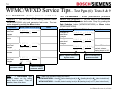
WFMC/WFXD Service Tips – Test Pgm (6): Tests 8 & 9
Test P8:NIVEAU1 (Analog pressure switch test
program) -- The test turns on the analog pressure switch
Test P9:NIVEAU2 / P:09 (Mechanical pressure
switch test program) -- The test turns on the mechanical
(WFMC64/WFXD84 only) and generates fault codes. The test
can be stopped by pushing the Menu button.
pressure switch and generates fault codes. Stop it by pushing the
Spin Selection button (WFMC32/WFXD52) or Menu button
(WFMC64/WFXD84).
Operation
Changes as
water level
changes
WFMC64/WFXD84 Display
D M P H
I00
V
1 2 3 N
0
n000
Calibrates analog
sensor
Changes as
water level
changes
D M P H
I65
V
1 2 3 NH
Notes
Operation
Changes as
water level
changes
WFMC64/WFXD84 Display
Changes as
water level
changes
D M P H
D M P H
I65
Offset of analog
pressure switch
V
U00
U03
U15
1 2 3 ND
Water volume measured
by flow meter
V
1 2 3 N0
V
1 2 3 NH
V
1 2 3 NH When n075 has been
n000
n075
D M P H
n075
Pauses for 10
seconds
Changes as
water level
changes
D M P H
Notes
n075
reached, volume
display jumps to U15.
Value of mechanical
pressure switch
n139
Value of analog
pressure switch
HINT:
If Start/Pause light
doesn’t come on for some
tests, door is open. Turn off
washer, then close door.
HINT: Water level symbols change as follows:
•
WFMC64/WFXD84 -- from N0 (below heating level) to NH (heating level) to ND (door locked level).
•
WFMC32/WFXD52 -- from 63 (below heating level) to 88 (heating level) to 177 (door locked level).
2nd Edition/Revision 0 (4/28/04)
/
75
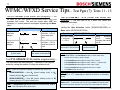
WFMC/WFXD Service Tips – Test Pgm (7): Tests 11 - 13
Test P11:FLOW (Flow meter test program) -- The
test turns on the flow meter (WFMC64/WFXD84 only) and
generates fault codes. The test has ended when U05 has
displayed (< 1 minute) and can be stopped by pushing the Menu
button.
Operation
Changes as
water level
changes
Changes as
water level
changes
WFMC64/WFXD84 Display
D M P H
U00
Water volume measured
by flow meter
1 2 3 N0
V
1 2 3 N0
F….
D M P H
U05
V
F….
Notes
Run test P1 to check
fault code -- if Er:13,
check water inlet
valve.
Run test P1 to check
fault code -- if Er:12,
check flow meter for
errors.
Flow rate measured by
flow meter in liters/minute
Test P12: UPDATE / P:12 (Update programming) -This test cannot be used presently. If selected, it can only be
exited by turning the washer off using the selector knob.
HINT: Water level symbols change as follows (e.g. test P13):
•
WFMC64/WFXD84 -- from N0 (below heating level) to NH
(heating level) to ND (door locked level).
•
WFMC32/WFXD52 -- from 63 (below heating level) to 88
(heating level) to 177 (door locked level).
HINT: If Start/Pause light doesn’t come on for some tests, door is
open. Turn off washer, then close door.
Test P13:VALVE1 / P:13 (Water inlet valves test
program) -- The test turns on all 3 water inlet valves and
generates fault codes.
It stops when n20 level is reached (max. 10 minutes). Stop it by
pushing the Spin Selection button (WFMC32/WFXD52) or
Menu button (WFMC64/WFXD84).
Operation
WFMC64/WFXD84 Display
Notes
Test runs valves D M P H
pressure
1 2 3 N Analog
D sensor
V
in sequence: 1,
reading
U22
n253
2, 1 + 2 & 3.
increases after valves
shut off.
Flow rate measured by
flow meter in liters/minute
Value of analog
pressure switch
HINT: On WFMC32/WFXD52, each valve is checked automatically. On
WFMC64/WFXD84, push Start/Pause button to check each valve:
• At start of test, valve 1 (cold) is tested.
• Push Start/Pause button again to check valve 2 (cold).
• Push Start/Pause button again to check valves 1 + 2 (dual cold).
• Push Start/Pause button again to check valve 3 (hot).
• Pushing Start/Pause button again checks valve 1 again.
• Push Menu button to exit test.
NOTE: On WFMC32/WFXD52, displays alternates from “P:13” to
“63”, “88” or “177”, depending on water level (below or at heating
level).
HINT: Test runs until max. water level reached or is stopped by pressing
Menu button. To save time with Test P13, press Menu to stop test when
all valves have been checked. Run Test P15 to drain washer if needed.
2nd Edition/Revision 0 (4/28/04)
/
76
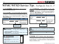
WFMC/WFXD Service Tips – Test Pgm (8): Tests 14 - 17
Test P14:BUZZER / P:14 (Buzzer test program) -Buzzer sounds when test is run.
Test P15:PUMP / P:15 (Drain pump test program) - The test turns on the drain pump and generates fault codes. The
test runs for ~ 30 minutes and can be stopped by pushing the
Spin Selection button (WFMC32/WFXD52) or Menu button
(WFMC64/WFXD84).
Operation
Filling (to door
locked level) and
draining
WFMC64/WFXD84 Display
D M P H
V
1 2 3 N0
n000
Notes
Can save time by
filling & then running
Drain cycle to check
for water draining.
Value of analog
pressure switch
HINT: Water level symbols change as follows (e.g. test P15):
•
WFMC64/WFXD84 -- from N0 (below heating level) to NH
(heating level) to ND (door locked level).
•
WFMC32/WFXD52 -- from 63 (below heating level) to 88
(heating level) to 177 (door locked level).
HINT: Start/Pause button light:
• Flashes red when tests can be selected or
scrolled through.
• Stays red continually (or stays off) when
tests are running.
• Doesn’t come on for some tests if door is
open.
Test P16:HEATER / P:16 (Heater & NTC test
program) -- The test turns on the heater & NTC and generates
fault codes. The test runs for ~ 30 minutes and can be stopped by
pushing the Spin Selection button (WFMC32/WFXD52) or
Menu button (WFMC64/WFXD84).
Operation
Changes as
water level
changes
WFMC64/WFXD84 Display
D M P H
V
Notes
1 2 3 N
H
t20
D M P H
V
1 2 3 NH During heating,
temperature display
rises to t86 max.
(86ºC/187ºF)
t22
Water temperature
in ºC
HINT: To save time with Test T16, press Menu to stop testing after the
temperature has gone up several degrees, confirming the washer is
heating OK.
NOTE: On Test T16, the water level rises until NH, which is the heating
water level.
P17:NOISE / P:17 (Factory noise test program) -Not relevant to customer service – do not use. This test is similar
to automatic test P3, except no heating is done and nothing is
shown on displays. This test merely turns on certain parts so the
factory can measure noise.
2nd Edition/Revision 0 (4/28/04)
/
77
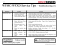
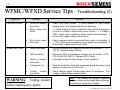
WFMC/WFXD Service Tips – Troubleshooting (1)
Symptom
Problem
Solution
Washer won’t start.
Electricity is disconnected
or has been turned off.
Cycle selector knob or
control module has failed.
Make sure washer is connected to an appropriate 120V, 60 Hz
circuit (according to local codes). Turn on electricity.
Control module has onboard cycle selector knob. Check
voltage output to water inlet valves and drum motor (when
they’re energized). If no voltage, replace faulty control module.
Washer won’t fill.
Water supply turned off.
Turn on water supply.
Water inlet hose filters
(strainers) blocked.
Check water inlet hose filters. Clean if dirty. Replace filters if
damaged.
Water pressure too low.
Control
module
has
failed.
Water inlet valve(s) has
failed.
Check incoming water pressure.
Check voltage output to water inlet valves (when they’re
energized). If no voltage, replace faulty control module.
Measure resistance of water inlet valves (~ 2.7 – 4.5 kΩ).
Replace inlet valve(s), if faulty.
Drain pump or pump
motor
protector
has
failed.
Control
module
has
failed.
Disconnect drain pump and measure resistance at connector
(~ 140 – 200 Ω). Replace drain pump if faulty.
Washer won’t drain.
WARNING! Unplug washer
before starting any repairs.
Check voltage output to drain pump when it’s energized. If no
voltage, replace faulty control module.
HINT:
The washer test program diagnoses
problems quickly and thoroughly where resistance
measurements usually aren’t needed.
2nd Edition/Revision 0 (4/28/04)
/
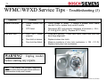
78
WFMC/WFXD Service Tips – Troubleshooting (2)
Symptom
Drum won’t rotate.
Washer won’t heat.
Problem
Solution
Drum rear bearing
has failed.
Check how drum rotates. If drum wobbles or won’t move,
replace outer tub (containing faulty rear bearings).
Motor control has
failed.
Check voltage at motor connectors when motor is energized.
If low or no voltage, replace faulty motor control.
If voltage ~
120V, check motor resistance (when washer de-energized). If
motor is OK, replace faulty motor control.
Drum drive motor
has failed.
Check voltage at motor connectors when motor is energized. If
~ 120V, check motor resistance (when washer de-energized). If
motor faulty, replace faulty drum motor.
Heater has failed.
Disconnect heater and measure resistance at terminals (~ 13.7 –
15.2 Ω). Replace heater if faulty.
NTC has failed.
Disconnect NTC and measure resistance at terminals (~ 22.8 –
27.4 k Ω @ 20ºC (68ºF)). Replace NTC if faulty.
Heater is covered
with scale.
If possible, remove & clean heater. If not, replace it.
Voltage too low.
Have an electrician check the house wiring and the wiring to the
washer to make sure it is 120 volts.
Control
module
has failed.
Check voltage output to drain pump when it’s energized. If no
voltage, replace faulty control module.
WARNING! Unplug washer
before starting any repairs.
HINT:
The washer test program diagnoses
problems quickly and thoroughly where resistance
measurements usually aren’t needed.
2nd Edition/Revision 0 (4/28/04)
/
79
WFMC/WFXD Service Tips – Troubleshooting (3)
Symptom
Washer overheats.
Door won’t lock.
Problem
Solution
Control module has
failed.
Check voltage to heater. If voltage is present when heater
shouldn’t be on, replace faulty control module.
NTC failed.
Disconnect NTC and measure resistance at terminals (~ 22.8 –
27.4 kΩ @ 20ºC (68ºF)). Replace NTC if faulty.
Door isn’t
properly.
closed
Close door securely. If door won’t latch, check door latch and
door hinge alignment.
Door latch is broken.
Replace broken door latch.
Door lock has failed.
Measure resistance of door lock mechanism (~ 159 - 211 Ω).
Replace faulty door lock mechanism.
WARNING! Unplug washer
before starting any repairs.
HINT:
The washer test program diagnoses
problems quickly and thoroughly where resistance
measurements usually aren’t needed.
2nd Edition/Revision 0 (4/28/04)
80
/
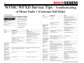
WFMC/WFXD Service Tips – Troubleshooting
of Minor Faults 1 (Customer Self-Help)
2nd Edition/Revision 0 (4/28/04)
81
/
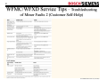
WFMC/WFXD Service Tips – Troubleshooting
of Minor Faults 2 (Customer Self-Help)
2nd Edition/Revision 0 (4/28/04)
/
82
WFMC/WFXD Service Tips – Customer Cleaning &
Maintenance
2nd Edition/Revision 0 (4/28/04)
/
83
WFMC/WFXD Service Tips – Oversudsing & Suds Lock
If washers time out and shut off without an end of cycle signal
(and without going through the spin cycle), the washer has
experienced suds lock, a possible occurrence with all front
loader washers (regardless of manufacturer).
• Suds lock:
Suds lock comes from suds (airy foam)
interfering with water level sensors (pressure switches).
Electronic controls are fooled into thinking water hasn’t been
removed fully, so washers won’t go into spin cycles. Drain
pumps can also get air locks in them.
• Cause:
Suds lock & oversudsing come from using too
much detergent, using the wrong kind of detergent (not HE) or
overloading washers (trapping suds in clothes).
• Solution:
Where oversudsing has occurred, have the
washer cleaned out every 6 months by running it without
clothing using a hot water wash (with cold water rinse) & ½
gallon of white vinegar. When suds have overflowed, run a
cold water rinse using 1 gallon of white vinegar. NOTE: Don’t
use vinegar routinely to avoid possible damage to washer
parts.
• Customer education:
Educate customer on type (HE)
and amount of detergent to use. To remove suds from clothes,
have customer rewash clothes with liquid fabric softener, ½
recommended amount of detergent & a cold water rinse.
TIP: Because front loader washers wash the
same amount of clothes more efficiently and
with much less water than top loader washers,
high efficiency (HE) detergent specially
formulated for front loader washers is needed.
Have customers follow detergent directions
and not expect to see suds.
TIP: Powdered detergent works better than
liquid detergents (due to more surfactants in
liquid detergents).
NOTE: Where possible, handle such calls
over the phone without making service calls.
2nd Edition/Revision 0 (4/28/04)