1
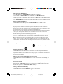
TE923W-M
PROFESSIONAL WEATHER STATION
WITH REMOTE CONTROL
USER MANUAL
1
TE923W IM1(ENG) HONEYWELL R.pmd
1
4/11/08, 5:21 PM
Table of Contents
Introduction .............................................................................................. 3
Standard Package Contents ...................................................................... 4
Installation ................................................................................................ 5
Before you begin ...................................................................................... 6
UV (Ultraviolet) Sensor ............................................................................ 7
Thermo-Hygrometer Sensor ..................................................................... 9
Rain Gauge ............................................................................................. 10
Anemometer (wind sensor) .................................................................... 12
Main Unit ................................................................................................ 14
Battery installation .................................................................................. 15
Buttons and Controls .............................................................................. 15
Operating mode descriptions .................................................................. 18
Customizing your Weather Station ......................................................... 21
LED Backlight Options .......................................................................... 21
Connecting the Weather Station to a PC................................................. 21
Using Different Weather Modes ............................................................. 22
Pressure and Weather Forecast Mode ..................................................... 22
UV Mode ................................................................................................ 25
Clock and Alarm Mode .......................................................................... 25
Manual Settings ...................................................................................... 25
Sunrise/Sunset Mode .............................................................................. 29
Temperature and Humidity Mode........................................................... 30
Rain Mode .............................................................................................. 32
Wind Mode ............................................................................................. 33
Maintenance............................................................................................ 34
Troubleshooting ...................................................................................... 35
PRECAUTIONS ..................................................................................... 35
Appendix - City Codes ........................................................................... 36
Specifications ......................................................................................... 40
FCC STATEMENT ................................................................................. 42
DECLARATION OF CONFORMITY ................................................... 42
STANDARD WARRANTY INFORMATION ....................................... 43
2
TE923W IM1(ENG) HONEYWELL R.pmd
2
4/11/08, 5:21 PM
Introduction
Thank you for selecting the Meade Instruments TE923WD-M Professional Weather Station with remote
control. This feature rich and easy-to-use product delivers a wide variety of time and weather data, such
as precise atomic time, perpetual calendar, air temperature, relative humidity, barometric pressure, wind
speed and direction, rainfall, UV levels and much more.
Meade Instruments is the world’s leading designer and manufacturer of telescopes for professional and
amateur astronomers - famous for its innovative, high performance telescopes at affordable prices.
Meade Instruments now brings that same passion innovation and high performance to its own line of
precision, feature rich weather stations.
In this package you will find:
• One Main Unit (receiver) (TE923WD-M)
• One IR Remote Control (TS607-M)
• One Rain Gauge (remote rain sensor/transmitter) (TS906-M)
• One Anemometer (remote wind sensor/transmitter) (TS805-M)
• One UV (ultraviolet) sensor (remote ultraviolet sensor/transmitter) (TS704-M)
• One Five-Channel Temperature & Humidity Sensor (transmitter) (TS34C-M)
• One CD disk with generic PC connection software with USB cable
• One 7.5V AC/DC Adapter
• Mounting Hardware with Allen Wrench
• One User Manual
3
TE923W IM1(ENG) HONEYWELL R.pmd
3
4/11/08, 5:21 PM
Standard Package Contents
Picture
Components
Main Unit
Remote Control
AC/DC 7.5V power adaptor
UV Sensor consists of:
Sensor Unit
U-Shaped Sensor holder
Circular Ground Stand
Stake Base
Wall-Mounting Base
Thermo Hygrometer Sensor
Rain Gauge consists of:
Funnel shaped top with battery
compartment
Rain Gauge bucket
Bucket see-saw mechanism
Protective screen
Anemometer consists of:
Wind Cups
Wind Vane
Anemometer arm
Anemometer base
PC Software
4 screws for securing rain gauge to the flat
surface;
4 screws for securing anemometer to vertical
surface
Mounting hardware
2m (6ft) USB cable
PC connection cable
4
TE923W IM1(ENG) HONEYWELL R.pmd
4
4/11/08, 5:24 PM
Required for installation (not included)
- Phillips screwdriver
- Mounting pole for anemometer (optional)
- Small paper clip for reset
Installation
The Professional Weather Station TE923W-M operates at 433MHz radio frequency
, so no wire installation is required between the main unit (receiver) and the remote weather
sensors (transmitters).
The remote weather sensors include a thermo-hygrometer (temperature and humidity) sensor, UV
(ultraviolet) sensor, anemometer (wind sensor) and a rain gauge (rain sensor). All data measured
by these remote sensors is transmitted to the main unit wirelessly, with the operating range up to
328 feet (100 meters) in open area.
Remote UV sensor, anemometer and a rain gauge must be placed outdoors to measure
weather elements.
Remote thermo-hygrometers can be placed indoors or outdoors, depending on the area where the
temperature and humidity are intended to be measured. If you intend measuring outdoor
temperature and humidity, place the remote sensor outdoors.
Note: It is critical to assemble and power up all of the remote weather sensors BEFORE setting
up the main unit.
Note: It is critical to power up and test communication between all of the weather sensors and the
main unit BEFORE permanently mounting them outside.
5
TE923W IM1(ENG) HONEYWELL R.pmd
5
4/11/08, 5:24 PM
Before you begin
• We recommend using alkaline batteries for the remote weather sensors and the main unit
when temperatures are above 32°F (0°C). We recommend using lithium batteries for the
remote weather sensors when temperatures are below 32°F (0°C).
• Avoid using rechargeable batteries. (Rechargeable batteries cannot maintain correct
power requirements).
• ALWAYS install batteries in the remote weather sensors before the main unit.
• Insert batteries matching the polarity in the battery compartment
• Remove and discard any factory applied protective plastic film affixed to the LCD display (if any).
• During an initial setup, place the main unit close to the remote weather sensors.
• After reception is established (all of the remote readings will appear on the main unit’s
display), position the remote sensors and the main unit within the effective transmission
range of up to 328 feet (100 meters). Ideally they should be placed within the line of sight
of the main unit. See placement tips in the user manual for each remote weather
sensor separately.
• Transmission range may be affected by trees, metal structures and electronic appliances.
• The main unit must be placed indoors.
• The effective operating range may be influenced by the surrounding building materials and
how the receiver (main unit) and transmitters (weather sensors) are positioned.
• Place the remote weather sensors so that they face the main unit (receiver), minimizing
obstructions such as doors, walls, and furniture.
Note: When the temperature falls below freezing, the batteries in the outdoor remote
weather sensors may have reduced voltage supply and a shorter effective range. We
recommend using lithium batteries at temperatures of 32 °F (0°C) and below.
IMPORTANT: Make sure that the remote weather sensors are easily accessible for cleaning
and maintenance.
We recommend cleaning the remote weather sensors periodically, as the dirt and debris may
affect sensors accuracy.
6
TE923W IM1(ENG) HONEYWELL R.pmd
6
4/11/08, 5:24 PM
Ultraviolet (UV) Sensor TS704-M
FEATURES
• Ultraviolet light levels measurement
• Remote UV levels data transmission to the main unit via 433MHz signal
• 328 feet (100 meters) transmission range
• Low battery indicator
• Three different placement options – ground, stake and wall
A
G
F
B
C
D
E
A. LED INDICATOR
• Flashes once when the remote sensor transmits a reading to the main unit
• Flashes twice when battery power is low
B. BATTERY COMPARTMENT SCREW
Holds battery compartment door in place
C. U-SHAPED SENSOR HOLDER
Holds UV sensor in upright position
D. CURCULAR GROUND STAND
Secures sensors in the sensor holder on the flat surface
E. UV SENSOR LID
Covers UV sensor and seals battery compartment
F. BATTERY COMPARTMENT
Holds two AA-size batteries
G. BATTERY COMPARTMENT DOOR
Covers two AA-size batteries
7
TE923W IM1(ENG) HONEYWELL R.pmd
7
4/11/08, 5:24 PM
Assembly
• Snap the U-shaped sensor holder onto the UV sensor unit side grooves
• Insert the round end of the U-shaped holder into one of the mounting hardware pieces provided
Battery installation
• Unscrew the lid on top of the UV sensor unit.
• Remove the screw from the battery compartment door with a small Phillips screwdriver
• Insert two 2 “AA” size 1.5V batteries (not included) matching the polarities shown in the
battery compartment.
• Replace the battery compartment door and secure the screw
• Screw the UV sensor unit lid back
Mounting
There are three different options available for mounting the UV sensor: ground stand, stake and
wall mount.
Ground
Ground:
• Insert the U-shaped sensor holder round end into the
circular ground stand opening, matching 2 round holes
in the opening
• Secure the sensor in a location with a maximum sun
exposure throughout the day.
Stake:
• Snap the sharp stake end onto the metal bar and secure
with the screws provided.
• Insert the other end of the metal bar into the U-shaped
sensor holder and secure with the screws provided.
• Secure the sensor in a location with a maximum sun
exposure throughout the day.
Stake
Wall:
• Insert the wall mounting end into the metal bar
Wall
and secure with the screws provided.
• Snap the other end of the metal bar on to the
U-shaped sens or holder and secure with the
screwsprovided.
• Secure the sensor in a location with a maximum
sun exposure throughout the day.
Placement tips:
The UV sensor should be mounted in the area free of sunlight shadows or reflections from the
nearby objects.
8
TE923W IM1(ENG) HONEYWELL R.pmd
8
4/11/08, 5:24 PM
Thermo-Hygrometer Sensor TS34C-M
FEATURES
• Remote data transmission to the main unit via 433 MHz signal
• 328 feet (100 meters) transmission range without interference
• LCD display of measured temperature and humidity
• Five (5) transmission channels selection
• Case can be wall mounted using built-in hanger
A. LED INDICATOR
• Flashes once when the remote sensor transmits a reading to the main unit.
• Flashes twice when battery power is low.
B. BATTERY COMPARTMENT
Holds two AA-size batteries
C. RESET
Resets all readings (requires small paper clip.)
D. CHANNEL SWITCH
Selects the desired channel from 1 to 5
E. WALL-MOUNT RECESSED OPENING
Keeps the remote sensor on the wall
Note: Install the batteries and select the channel before mounting the sensor.
Battery installation
• Remove the screws from the battery compartment with a small Phillips screwdriver.
• Set the channel 1 through 5. The switch is located in the battery compartment. Channel 1 is
typically selected if only one remote sensor is being used.
• Install 2 “AA” size alkaline batteries (not included) matching the polarities shown in the battery
battery compartment.
• Replace the battery compartment door and secure the screws.
• Secure the thermo-hygrometer remote sensor in the desired location.
Mounting
• The remote thermo-hygrometer sensor can be placed on the flat surface or mounted on the wall
in vertical position
• Use the wall mount hardware and screws provided when mounting the thermo-hygrometer
sensor on the wall
Placement tips:
• The remote thermo-hygrometer sensor should be placed in the area with a free air circulation
and sheltered from the direct sunlight and an extreme weather conditions.
• Ideally, place the thermo-hygrometer sensor above the natural surfaces (such as a grassy lawn).
• Avoid placing the thermo-hygrometer sensor near sources of heat such as chimneys and heating
elements.
• Avoid any areas collecting and radiating a heat from the sun, such as metal, brick or concrete
structures, paving, patios and decks.
• The international standard for the valid air temperature measurements is 4 feet (1.25meters)
above the ground.
9
TE923W IM1(ENG) HONEYWELL R.pmd
9
4/11/08, 5:24 PM
Rain Gauge TS906-M
FEATURES
• Precipitation measurement
• Remote rainfall data transmission to the main unit via 433 MHz signal
• 100 feet (30 meters) transmission range without interference
• Built-in installation level
• Non-corrosive protective screen
B
A
C
A. Rain gauge bucket
Contains electronic components
B. Knob
Secures the top on the rain gauge bucket
C. Rain gauge feet
Secures the rain gauge in place
G
D
E
H
F
I
D. Funnel-shaped top with battery compartment
Contains battery compartment and rainfall counting electronics
E. Battery compartment
Holds two AA-size batteries
F. Screws
Secure battery compartment cover
G. Built-in level with bubble
Ensures level rain gauge mounting for proper operation
H. Bucket see-saw mechanism
Collects the rainfall in one of its containers and self-empties once full
I. Protective screen
Protects the rain gauge funnel from debris
10
TE923W IM1(ENG) HONEYWELL R.pmd
10
4/11/08, 5:25 PM
Battery installation
• Unlock the funnel-shaped top on the rain gauge by turning both knobs on the sides in an anticlockwise direction.
• Remove the funnel-shaped top lifting it off the rain gauge bucket.
• Remove 7 small screws from the battery compartment cover using a small Phillips screwdriver
• Insert 2 “AA” size alkaline batteries (not included), matching the polarities as shown in the
battery compartment.
• Replace the battery compartment door and secure the screws.
• Insert the funnel-shaped top into the rain gauge bucket and secure it into place by turning the
knobs clockwise.
Mounting
• Make sure that the rain gauge bucket is level – check for bubble center, inside built-in level.
• Place the protective screen over the top to protect the rain gauge from the debris.
• Where practical, mount the rain gauge in place with wood screws (not included).
• Make sure that the rain gauge is in open area where precipitation falls directly into the gauge’s
bucket, ideally 2-3 feet above the ground.
Placement tips
• The rain gauge should be placed in an open area away from the walls, fences, trees and other
coverings which may reduce the amount of rain falling into the bucket. Additionally, trees and
rooftops may be sources of pollen and debris.
• To avoid the rain shadow effects, place the rain gauge horizontally, on the distance
corresponding to two to four times the height of any nearby obstruction.
• It is important to locate the unit where rain can flow freely away.
11
TE923W IM1(ENG) HONEYWELL R.pmd
11
4/11/08, 5:25 PM
Anemometer (wind sensor) TS906
FEATURES
• Wind speed and wind direction measurement
• Remote wind speed and wind direction data transmission to the main unit via 433 MHz signal
• Operating range 100 feet (30 meters)
• Wall or pole mount
A
B
D
C
A. WIND VANE
Measures wind direction
B. WIND CUPS
Measures wind speed
C. ANEMOMETER BASE
• Holds battery compartment
• Allows mounting the anemometer vertically
D. ANEMOMETER ARM
Keeps anemometer assembly together
E
G
F
H
E. WIND CUPS SHAFT
Holds wind cups on the anemometer arm
F. BATTERY COMPARTMENT
Holds 2 AA-size batteries
G. WALL MOUNT SCREW OPENINGS
Allows securing the anemometer in place
H. BATTERY COVER
Allows securing 2 AA size batteries on the anemometer base
12
TE923W IM1(ENG) HONEYWELL R.pmd
12
4/11/08, 5:26 PM
Assembly
• Slide the wind cups on to the anemometer rotating shaft. Do not use force.
• Insert the Allen Wrench (provided) into the wind cup set screw opening. Tighten the set screw
to secure wind cups to the rotating shaft.
• Test to ensure cups are securely fastened to the shaft.
Battery installation
• Remove four (4) screws from the battery compartment with a small Phillips screwdriver.
• Open the battery compartment and install 2 “AA” size alkaline batteries (not included)
matching the polarities shown.
• Replace the battery compartment door and secure the screws.
Aligning
• Point the wind direction vane to the north (use a compass or map if necessary).
• Press the button inside the “SET” opening located inside battery compartment with a paper clip
or similar tool. The “SET” selects a new direction for NORTH and, when pressed repeatedly,
alternates between the factory default NORTH and user selected NORTH.
• Select the factory set mode. It will be also a default setting in the future.
• Set current wind direction as NORTH.
Note: Repeat this procedure every time when changing the batteries.
Mounting
Mount the anemometer onto a vertical surface, using the fittings provided.
Placement tips:
• The anemometer should be mounted in an open area with a free air flow; away from the nearby
trees, buildings or other structures.
• For optimal performance, mount the anemometer at 33 feet (10meters) above the ground in
unobstructed area.
13
TE923W IM1(ENG) HONEYWELL R.pmd
13
4/11/08, 5:26 PM
Main Unit
The main unit measures pressure, indoor temperature, humidity, and receives atomic time data
from the US Atomic Clock and all remote weather sensors. It should be placed indoors.
FEATURES
Time
• Precise time and date set via RF signals from US Atomic clock
• 12 or 24 hour time format
• Manual adjustment of time and date
• Calendar displaying date with month and day in 6 languages English, German, French,
Italian, Spanish and Dutch
• Sunrise/set calculation for over 100 pre-programmed world cities in accordance with the
geographical information entered by the user
• Moon Phase calendar and historical data for the past and future 39 days
• Dual crescendo alarms with programmable snooze
Weather
• Weather forecast for the next 12 to 24 hour in seven large icons: Sunny, Partly Cloudy,
Cloudy, Light Rain, Heavy Rain, Unstable Weather and Snowy
• Barometric pressure in imperial or metric units
• Altitude adjustment for pressure compensation
• 24 hour barometric pressure history chart
• Multiple weather alerts including: Hi/Low temperature, Daily Rainfall, Hi wind gust and Hi
wind speed alerts
• Indoor/Outdoor Temperature & Humidity in up to 5 remote locations (additional
sensors required)
• Dew point and comfort level indicators
• Wind speed and wind gust averages and memory
• Wind direction
• Rainfall amount with minimum and maximum memory
• UV intensity with daily and weekly highs and lows
• 200 weather records without PC connection
• PC software (included) and USB port
• Operating range from 100 feet (30 meters) up to 328 feet (100 meters)
Display
• Light sensor detects low light conditions and LCD lights up automatically when adapter
is connected
• Infrared remote control of all display functions
Power - Main Unit
• AC/DC adapter for automatic remote control
• 4 AA batteries
Power - Infrared Remote Control
• 2 AAA batteries
14
TE923W IM1(ENG) HONEYWELL R.pmd
14
4/11/08, 5:26 PM
Battery installation
• Open the battery compartment door on the back of the main unit.
• Insert four (4) AA size batteries according to the polarities shown and replace the battery
compartment door.
• Connect 7.5V AC/DC adapter provided to the main display unit and plug into the wall power
outlet.
Note: The AC/DC adaptor connection is required for automatic backlight control and a
handheld remote control functions. If the main unit operates solely on the battery power, the
auto backlight control and handheld remote control functions will be disabled.
• When placing the main unit on the table or other horizontal surface, unfold the table stand
adjusting it to the desired viewing angle.
• When mounting the main unit on the wall or vertical surface, fold the table stand back into the
unit and use the mounting hardware provided.
Placement tips
• Make sure that the main unit is locating within the operating range of all remote weather
sensors.
• Ideally the remote weather sensors should be mounted within the line of sight of the main unit.
• Transmission range may be affected by trees, metal structures and electronic appliances.
• Test reception before permanently mounting all the remote weather sensors.
Avoid placing the main unit in the following areas:
• Direct sunlight and surfaces emitting and radiating heat, such as heating ducts or air
conditioners.
• Areas with interference from the wireless devices (such as cordless phones, radio headsets, baby
listening devices) and electronic appliances.
Operation
Once the main unit is powered, the display will show all available LCD segments for a moment.
IMPORTANT: All of the display functions will be locked, allowing setting your local altitude and
pressure parameters. The locked display will show the pressure icon and abbreviation “inHg”
flashing, indoor temperature and humidity readings, default time and default sunset/sunrise time.
If pressure and altitude are not configured during this time, the unit will self-calibrate in a few
minutes and show the default settings for the pressure and altitude (sea level) and all remote
weather sensors readings.
IMPORTANT: If not set during the initial setup, the altitude cannot be adjusted or set at any other
time. In order to set the altitude, you will have to restart the main unit completely.
15
TE923W IM1(ENG) HONEYWELL R.pmd
15
4/11/08, 5:26 PM
To set the pressure & altitude units and program your altitude, use the handheld remote control or
main unit control panel:
G
H
I
A
B
C
D
E
F
Buttons and Controls
Most of the handheld remote control buttons are corresponding to the main unit controls.
To expose the main unit control buttons, press the OPEN button on the upper right corner of the
main unit and the controls’ cover door will open.
Main unit and handheld remote control adequate buttons
A.UP
B. DOWN
- Selects the next available mode anti-clockwise
- Increases parameters
- Selects the next available mode clockwise
- Decreases parameters
C. SET
- Rotates display for current mode
- If depressed and hold, enters into the programming mode or changes
parameter’s units
- Confirms set parameters
D. MEMORY
- Allows displaying the moon phase, UV, temperature, humidity, rainfall
and wind memory records
E. HISTORY
- Allows displaying the sea-level pressure history
F. ALARM/
CHART
- Allows displaying the time alarms and alerts for the temperature, rainfall
and wind.
- If depressed and hold, allows entering into the alarm/alert
programming mode
- When depressed and hold in pressure and forecast mode, allows viewing
of the different bar charts
G. CHANNEL
- Changes the temperature and humidity channel- Enables the temperature
and humidity channel auto-scan mode
H. LIGHT/
SNOOZE
- Enables a backlight for 5 seconds- Snoozes the alarms
16
TE923W IM1(ENG) HONEYWELL R.pmd
16
4/11/08, 5:26 PM
Main unit only
I. OPEN
- Opens the control buttons panel on main unit
J. LIGHT SENSOR– AUTO,
ON, OFF
- Toggles the light sensor to automatic, on or off
setting
K. SENSITIVITY– HIGH/
LOW
- Adjusts the light sensor sensitivity
Handheld remote control TS607 (Seletions)
Temperature and
Humidity Mode
- Selects the Temperature and Humidity Mode
Wind Mode
- Selects the Wind Mode
UV Mode
- Selects the UV Mode
Pressure and Weather
Forecast Mode
- Selects the Pressure and Weather Forecast Mode
Rain Mode
- Selects the Rain Mode
Sunrise/Sunset Mode
- Selects the Sunrise/Sunset Mode
Clock and Alarm
Mode
- Selects the Clock and Alarm Mode
Change Bar-chart
Display
- Selects 24 hour History Bar-chart.
- Alternates between Pressure, Channel 1 Temperature,
or Channel 1 Humidity
17
TE923W IM1(ENG) HONEYWELL R.pmd
17
4/11/08, 5:26 PM
Operating mode descriptions
The main unit has seven (7) different modes (windows) each displaying the separate data
category. When a specific mode is selected the corresponding icon will start flashing.
Press UP button on the main unit or the handheld remote control to cycle through the modes
clockwise or DOWN anti-clockwise.
Pressure and Weather Forecast Window
Displays:
• Current pressure and history bar-chart
• Weather forecast
• Moon phase
Note: For altitude display of 99o this is actually 990 feet, etc.
UV Window
Displays:
• UV index or Minimum Ultraviolet Exposure
• Daily Maximum
• Weekly Maximum
• Remote UV sensor battery status
18
TE923W IM1(ENG) HONEYWELL R.pmd
18
4/11/08, 5:27 PM
Clock and Alarms Window
Displays:
• US Atomic Time clock with time and calendar
• Single alarm, weekday alarm and ice warning alarm (pre-alarm)
Sunrise/Sunset Window
Displays:
• Sunrise and sunset times
• Longitude and Latitude
Temperature and Humidity Window
Displays:
• Temperature and humidity readings for indoor and selected channel
• Comfort level indication
• Dew point temperature
• High and Low temperature alerts
• Remote Thermo-Hygrometer sensor battery status
Cycling Display
Dew-point Tempature
Sensor Battery Status
Channel Temp.
Channel Humidity
Channel and
Reception status
Temp. Alert
Min-Max Display
Comfort Level
Tempature and Humidity
Mode Icon
Indoor Temp.
Indoor Humidity
19
TE923W IM1(ENG) HONEYWELL R.pmd
19
4/11/08, 5:27 PM
Rain Window
Displays:
• Precipitation amount for the last hour, day, yesterday, last week and last month
• Rainfall alert
• Remote rain gauge battery status
Wind Window
Displays:
• Wind Chill temperature
• Temperature at place of anemometer
• Wind direction
• Wind speed
• Wind gust speed
• Alert for wind speed and wind gust speed
• Remote anemometer battery status
Needle
20
TE923W IM1(ENG) HONEYWELL R.pmd
20
4/11/08, 5:27 PM
Customizing your Weather Station
It is required to program:
• The pressure parameters during Initial Setup (See Pressure and Weather Forecast Mode P.22)
• The time, the date and the weekday language (Clock and Alarm Mode: P.25)
• The location data (Sunrise/Sunset Mode: P.29)
Optional:
• The time alarms (Clock and Alarm Mode: P.25)
• The temperature alerts (Temperature and Humidity Mode P.30)
• Daily rainfall alerts (Rain Mode P.32)
• Wind alerts (Wind Mode: P.33)
LED Backlight Options
The main unit backlight can be turned on, off or automatically toggled depending on the
environment light conditions. Use the light sensor switch at the back of the main unit to select a
desired backlight setting.
For the automatic backlight control, the sensitivity of the light sensor can be adjusted to high or
low using the switch, located on the back panel.
Note: For an automatic control function the main unit must be plugged into the wall power
outlet via the AC/DC adaptor provided.
Connecting the Weather Station to a PC
Data collected by the weather station can be displayed on PC by connecting the main unit to the
computer via USB cable.
• Install the software provided with the weather station according to the instructions in the
software manual.
• Connect the main unit to the computer using the USB cable provided.
21
TE923W IM1(ENG) HONEYWELL R.pmd
21
4/11/08, 5:27 PM
Using Different Weather Modes
Pressure and Weather Forecast Mode
It indicates the current barometric pressure, the sea level pressure, the weather forecast and the
moon phase.
A number of historical statistics can also be viewed, including the sea-level pressure for the past
24 hours, moon phase for the past and following 39 days, as well as a pressure/ temperature/
humidity history bar-chart.
Pressure can be displayed inHg, hPa/mBar or mmHg, and altitude can be displayed in meters
or feet.
Accessing Pressure and Weather Forecast Mode
Press main unit UP or DOWN until the weather forecast icon
left corner.
From the remote control: Press
to flash, upper display
.
Setting Initial Pressure Parameters
Overview
Local Pressure, Sea Level Pressure and Altitude are interdependent. The weather station is
designed to measure local pressure and calculate the other two parameters. If you enter altitude,
it will calculate sea level pressure, if you enter sea level pressure, and will calculate altitude.
During initial power up (within the first two minutes) the weather station will not operate until
the Pressure & Altitude parameters are entered. The icon in the upper left hand corner begins
flashing. If no values are entered at this time, after two minutes the unit will switch to the
default settings of: inHG (Inches of Mercury), and 33 FEET. These parameters can be changed
as desired at a later date, using the steps outlined in the section for Setting or Changing Pressure
and Altitude settings.
1. Setting Pressure and Altitude during initial setup (first two minute only)
• Press UP or DOWN button selecting the units of pressure in: inHg (inches of mercury),
hPa/mBar (hectoPascal) mmHg (millimeters of mercury)
• Press SET to confirm and store selection. The unit will advance to altitude unit selection.
• Press UP or DOWN button selecting the altitude unit in FEET or METERS.
• Press SET button to confirm and store. The unit will advance to the altitude programming
mode.
• Press UP or DOWN to adjust the local altitude. Press and hold either button for “Rapid”
settings. Press SET to confirm the programmed value.
• (Local information is obtainable via GPS device or online services like GOOGLE.)
• After about 30 seconds the unit will calculate & display the Sea Level pressure.
• DO NOT PRESS ANY ADDITIONAL BUTTONS for about 5 minutes as the unit is
now searching for remote sensors and need time for measurements to settle down.
Viewing the Pressure and Altitude Information
Wait at least 5 minutes after initial set up to view a pressure or altitude information. Briefly
press SET button to alternate between the sea level pressure, local pressure and local altitude
altitude settings.
22
TE923W IM1(ENG) HONEYWELL R.pmd
22
4/11/08, 5:27 PM
2. Changing Pressure and Altitude
Select the Pressure and Weather Forecast window. From the main unit: Press UP or DOWN until
the pressure and weather forecast icon starts flashing.
Changing or Setting Sea Level Pressure
• Press SET until the local pressure with the word “SEA LEVEL” is displayed.
• Press and hold MEMORY until the pressure unit is flashing, inHG, mmHG or hPa/mBar
• Set the sea level pressure units by pressing the UP or DOWN buttons to adjust the
pressure value.
• Press MEMORY to confirm your selection.
Changing or Setting Altitude
• Press SET button until the local altitude value will be displayed
• Press and hold MEMORY until the altitude unit is flashing, FEET or METERS.
• Set the altitude unit in meters or feet by pressing the UP or DOWN.
• Press MEMORY to confirm your selection.
NOTE: Locate your altitude with a portable GPS receiver or topographical map .Locate
barometric pressure at: http://weather.noaa.gov/weather/ccus.html or alternatively, barometric
pressure can be obtained from local radio or TV weather channels.
Viewing the Sea Level Pressure History
• From any mode, press the HISTORY button. Unit will select the Pressure/ Weather display.
• When the SEA LEVEL is displayed, press HISTORY repeatedly viewing the sea level pressure
history for the past 24 hours in hour increments.
• If no buttons are pressed for 5 seconds, the unit will automatically exit HISTORY and return to
the Pressure and Weather Forecast Mode.
Viewing the Pressure, Temperature and Humidity Bar Charts
The pressure bar graph shows barometric pressure variations over the past 24 hours. This is very
useful for understanding the Barometric trends that are used in weather forecasting. Each bar icon
represents 0.06 inHg.
Alternatively, the bar chart can be used to display 24 hour trend data for Sea Level Pressure, CH 1
Remote temperature or Ch1 Remote humidity.
Select the Pressure and Weather Forecast window, press and hold ALARM/CHART button to
toggle the bar chart title at the right bottom corner of the chart. Alternate between “PRESSURE”
“CH1”temperature (thermometer icon) and “CH1” relative humidity with (RH icon)”.
Viewing the Moon Phase History
The unit indicates the current moon phase and using the MEMORY control, will permit viewing of
past of future days. Previous moon phases are selected with the minus sign selected: -1 day, -2
days, etc or future moon phase are selected based on the days ahead: +1 day, + 2 days, etc up to 31
days.
• After selecting the Pressure and Weather Forecast Mode, press MEMORY, so “+ 0 days” is
flashing.
• Press UP or DOWN selecting from today’s date a future (+) or past (-) days and the
corresponding moon phase will be displayed. Press and hold either button for a quick advance.
• To exit, press MEMORY button.
23
TE923W IM1(ENG) HONEYWELL R.pmd
23
4/11/08, 5:27 PM
Weather Forecast Displays
Display
Weather Forecast
Sunny
Partly Cloudy
Cloudy
Light Rain
Heavy Rain
Unstable Weather
Snow
Note: The weather forecast accuracy is approximately 70%.
Display shows forecasted, not current conditions. The SUNNY icon indicates clear weather,
even when displayed during the night-time.
24
TE923W IM1(ENG) HONEYWELL R.pmd
24
4/11/08, 5:27 PM
Understanding the Moon Phase Diagram
FULL
LAST
NEW
FIRST
UV Mode
The current UV intensity is indicated by the numerical value and more intuitive display, by
categorizing it into the levels “LOW”, “MED”, HIGH”, V. HIGH” and EXTREME. It is also
represented by a comfort icon that corresponds to different levels.
The main unit records the daily and weekly maximum UV intensity. Values may be displayed in
MED/h or UVI.
Accessing UV Mode
From the main unit: Press UP or DOWN until the UV icon
the handheld remote control: Press
on the display will flash. From
.
Viewing UV Statistics
In UV Mode press the MEMORY button viewing either current UV intensity, daily Maximum UV
intensity with “DAILY MAX” displayed or weekly Maximum UV intensity with a “WEEKLY
MAX” displayed.
Resetting the UV Statistics Memory
In UV Mode, press and hold MEMORY to reset all UV statistics.
Setting Units for UV Display (MED/h or UVI)
In UV Mode, press and hold SET to convert units between MED/h and UVI.
Clock and Alarm Mode
Manual Settings
The main unit can be manually set to display the time, calendar or UTC time. There are three time
alarms available on the main unit: Weekday alarm (W), Single alarm (S) and Ice Warning Alarm
(Pre-Al).
• If Weekday alarm is activated, it will sound at the set time and the alarm icon will flash
Mondays through Fridays.
• If Single day alarm is activated, it will sound at the set time and the alarm icon will flash only
for this specific day and will not activate on subsequent days.
• The Ice Warning Alarm is activated at programmed time interval (from 15 to 90 minutes)
before the weekday or single alarm, if channel 1 temperature falls to freezing and below.
Note: The snooze duration for listed alarms can also be programmed up to 15 minutes.
25
TE923W IM1(ENG) HONEYWELL R.pmd
25
4/11/08, 5:28 PM
Accessing Clock and Alarm Mode
Press main unit UP or DOWN until the clock icon
next to the time/date display continues
to flash.
From the handheld remote control: Press
.
Setting the time, date and language
• In the Clock and Alarm Mode, press and hold SET button until the day of week language
abbreviation “ENG” will flash.
• Press UP or DOWN selecting the day of the week in English, German, French, Italian, Spanish
or Dutch
• Press SET to confirm selection.
• Select the City Code for your area by pressing UP or DOWN. Refer to P.36 for a list of
available codes.
• Press SET to confirm the city selection and if your selected USR for city. This overrides the
automatic latitude and longitude pre programmed for each city. You will be prompted to enter
the latitude, longitude, Time Zone and select the Daylight Savings Time on or off. (Go to P.36
for programming detail.)
• Press UP or DOWN to adjust the latitude. Press and hold either button for quick digits advance.
• Press SET to confirm the selection.
• Continue setting the longitude using the same technique.
• Set the Time Zone by pressing UP or DOWN to adjust the time in 30 min intervals. Press and
hold either button for quick digits advance.
• Press SET to confirm selection.
If the USR was selected as a city code or your city is located in the Daylight Savings zone you
would need to set the Daylight Saving Time Option:
• Press UP or DOWN to enable or disable the DST option. Press and hold either button for quick
digits advance.
• Press SET to confirm selection.
• Continue setting the year, month, day, calendar format (day/month or month/day), time format
(12 or 24 hours), local hour and minutes, using the same technique.
After programming is completed, the display will return to the default Clock and Alarm Mode.
Note: Press and hold SET anytime during the setup to return to normal Clock and Alarm Mode
and all previous settings will be cancelled.
Clock and Calendar Displays
Briefly press the SET button to alternate between the 5 Clock & Calendar displays:
• Time with the Day of the week
• Time for UTC (Coordinated Universal Time)
• Time with the City abbreviation
• Time with the Seconds
• Month/ Day/ Year or Day/ Month/ Year.
26
TE923W IM1(ENG) HONEYWELL R.pmd
26
4/11/08, 5:28 PM
Enabling or Disabling the Time Alarms
• Press the ALARM/CHART to display the Weekday Alarm or Ice Warning Alarm (Pre-Alarm)
time. If these alarms are not set, the abbreviation OFF will be displayed.
• To enable or disable any of these alarms, press UP or DOWN.
Note: Press SET anytime during alarm selection mode to return to the default clock display.
Programming Time Alarms
• In the Clock and Alarm Mode, press the ALARM/CHART selecting the desired alarm.
• Press and hold ALARM/CHART button until the hour digit will flash
• Set the alarm hour using UP or DOWN. Press and hold either button for quick digit advance.
• Press ALARM/CHART to confirm selection.
• Set the alarm minutes using UP or DOWN. Press and hold either button for quick digit advance.
• Press ALARM/CHART to confirm selection.
• Set a Snooze interval (all three alarms share same snooze time duration) using UP or DOWN.
Press and hold either button for quick digit advance.
• Press ALARM/CHART to confirm your selection.
After programming is completed, the display will return to the alarm selection screen.
Disabling or Enabling Snooze function
To enable a snooze function press LIGHT/SNOOZE button.
Note: Alarm will automatically enter the snooze mode if no buttons are pressed after the alarm
sounds for 2 minutes. This will occur for a maximum of three times.
To disable alarm(s):
Press ALARM/CHART to disable the alarm (s).
Note: For weekday alarm, pressing ALARM/CHART will only disable the alarm for the current
day. The alarm will activate again on the next day, Monday through Friday.
27
TE923W IM1(ENG) HONEYWELL R.pmd
27
4/11/08, 5:28 PM
Atomic Time Reception
The radio controlled clock will automatically search for, and synchronize to, the NIST (National
Institute of Standards and Technology) Atomic clock signal transmitted at 60 KHz from Colorado.
It synchronizes the weather station clock with a precise time signal that is transmitted
continuously throughout the entire continental United States.
The WWVB tower icon flashes on the display, during intervals when the WWVB radio signal is
being received.
• During night-time hours, atmospheric disturbances are typically less severe and radio signal
reception may improve. A single daily reception is sufficient enough to keep the clock accuracy
within 1 second.
• Make sure the unit is positioned at 8 feet (2 meters) distance from any interference source such
as a TV, computer monitor, microwave, etc.
• Within concrete wall rooms such as basements or office buildings, the received signal may be
weakened. Always place the unit near the window for better reception.
Once the atomic time signal is received, the date and time will be set automatically, and the [
icon will appear.
]
Place the main unit by the window for the better reception. The atomic clock receiver is
programmed that it will continue to search for the atomic time signal daily for every hour between
1:00 am and 4:30 am.
Once the time signal has been successfully received, the time and date will be
updated automatically.
To enable or disable the atomic time receiver:
• Press and hold UP - if atomic time reception is activated, a triangular tower icon will start
flashing next to the clock icon. If reception is disabled, the triangular tower icon will disappear.
Icon
Atomic Time Reception Strength
Undefined data
(Flashing)
No reception for 24 hours
Weak signal, but can be decoded
Strong signal
28
TE923W IM1(ENG) HONEYWELL R.pmd
28
4/11/08, 5:28 PM
Sunrise/Sunset Mode
The main unit is able to calculate the sunrise and sunset times depending on the user defined
location. The location data contains from the longitude, latitude, time zone and DST (Daylight
Saving Time).
Select the closest to your area city code and the main unit will automatically generate all of the
correct data for specified location.
If you cannot find the closest city code or would like to enter your specific location, select “USR”
as the city code during the setup.
A search function is also available. It allows viewing the sunrise/ sunset times for different dates.
Accessing Sunrise/Sunset Mode
Press main unit UP or DOWN until the sunrise and sunset icons
the display will start flashing.
From the remote control: Press
on the lower left of
.
Programming the Location Data
• In Sunrise/Sunset Mode, press and hold SET to enter the location programming mode until the
city code in the Time and Alarm display will flash.
• Select the city code closest to your area by pressing UP or DOWN. Refer to P.37 for a list of
available codes. The corresponding longitude and latitude will be displayed in Sunrise/Sunset
window along with the city code.
• If you wish to enter the geographical coordinates yourself, select the “USR” as the city code.
• Press SET to confirm your selection and enter into the geographical coordinates programming
programming mode
Set Degree of Latitude
• Press UP or DOWN to adjust the digits. Press and hold either button for fast advance.
• Press SET to confirm your selection.
• Repeat above procedure to set latitude and longitude minutes, longitude degrees, time zone, and
DST selection.
• Once programming is completed, the display will return to the Sunrise/Sunset Mode.
Note: Press and hold SET anytime during the setup to return to normal Clock and Alarm Mode.
All settings will be cancelled.
Viewing the Location Data
In Sunrise/Sunset Mode, press SET button to select between the time and sunrise/ sunset times
mode display, calendar and sunrise/ sunset times display and a calendar and longitude/ latitude
latitude display.
Viewing Sunrise/Sunset Times for Different Dates
• In Sunrise/Sunset Mode, press the MEMORY button until the date will flash.
• Press UP or DOWN to adjust the date. Press and hold either button for fast digits advance.
• The corresponding sunrise and sunset times will be displayed for the selected date.
• Press MEMORY or SET to return display to the Sunrise/Sunset Mode.
29
TE923W IM1(ENG) HONEYWELL R.pmd
29
4/11/08, 5:28 PM
Understanding of the Sunrise/Sunset Display
The sunrise time displayed in the morning will be different from the one displayed in the
afternoon/night:
From 12 am to 12 pm the current day sunrise time will be displayed.
From 12 pm to 12am the next day sunrise time with the “NEXT DAY” icon will be displayed
At some locations, especially with high latitudes, sunrise and sunset events may not occur within
24 hours.
Display
Sunnrise status
Display
FULL
Sunrise for the previous day
----
No sunrise for the whole day
FULL
- ---
Sunset status
Sunset on the following
day or later
No sunset for the whole
day
Temperature and Humidity Mode
The weather station supports up to 5 remote thermo hygrometers, corresponding to a separate
channel of the temperature and relative humidity display. The temperature can be displayed in
Celsius (ºC) or Fahrenheit (ºF).
The main unit carries the temperature and humidity sensor and uses this indoors data to calculate
an indoors comfort level - Wet, Comfort or Dry.
A temperature alert function is available for each channel. It can be programmed to sound if the
channel temperature exceeds or falls below the pre-set upper and lower limit.
Note: The temperature alerts have a 0.5 ºC deviation to prevent them from sounding due to small
temperature fluctuations that are close to the set alert value. This means that after the temperature
reaches the alert temperature, it will have to fall below the alert temperature plus the deviation
(0.5°C) to activate the alert.
30
TE923W IM1(ENG) HONEYWELL R.pmd
30
4/11/08, 5:28 PM
Accessing Temperature and Humidity Mode
Press main unit UP or DOWN until the IN icon
From the remote control: Press
on the upper right will flash.
.
Viewing Temperature and Humidity for each Channel
Static Display:
In Temperature and Humidity Mode, press the CHANNEL button to recall a different channel.
Channel Auto-Scan Display:
To enable automatic scan of the different channels, press and hold CHANNEL, until the
is displayed. Each valid channel will be alternately displayed with a 5 seconds delay.
icon
Recalling of Temperature and Dew Point Displays
In Temperature and Humidity Mode, press the SET button to recall temperature and relative
humidity or dew point and relative humidity.
Set the Temperature in Celsius or Fahrenheit.
In Temperature and Humidity Mode, press and hold the SET button to toggle the temperature in
Celsius (ºC) or Fahrenheit (ºF).
Activating/Deactivating the Temperature Alerts
In Temperature and Humidity Mode, press the ALARM/CHART button to recall a current
temperature for the corresponding channel, the upper temperature alert with
icon (if disabled,
displays OFF), or lower temperature alert with
icon (if disabled, displays OFF).
Once the above alerts are displayed, press UP or DOWN to enable or disable the corresponding alert.
Programming the Temperature Alerts
• In the Temperature and Humidity Mode, press the ALARM/CHART button selecting the
desired alarm.
• Press and hold the ALARM/CHART button until the remote temperature and
or
icon
starts flashing.
• Adjust the temperature digits for the Temperature Alert using the UP or DOWN. Press and hold
either button for fast digits advance.
• Press the ALARM/CHART button to confirm selection and return to the temperature alert
selection screen.
Disabling Temperature Alarm(s)
In the Temperature & Humidity Mode, press the ALARM/CHART button to disable the alarm(s).
Viewing the Max/Min Channel Temperature and Humidity
In the Temperature & Humidity Mode, press the MEMORY button to recall a current temperature
and humidity, minimum temperature and humidity or maximum temperature and humidity at the
remote location.
Resetting the Remote Temperature and Humidity Memory
In the Temperature and Humidity Mode, press and hold the MEMORY button to clear memory
for all channels.
31
TE923W IM1(ENG) HONEYWELL R.pmd
31
4/11/08, 5:28 PM
Remote Sensor Status
The wave icon above the current channel display shows the connection status of the corresponding
remote sensor:
Icon
Status
Searching for the signals from the remote sensor
Corresponding remote sensor signal received successfully
No signals received for over 15 minutes
All Remote Sensor Signals Search Activation
The main unit can be manually activated to search for the signals from all remote sensors.
Press and hold the DOWN button to enable the search.
Rain Mode
The main unit records the total amount of the rainfall for the last hour, 24 hours, past day, past
week and the past month. The rainfall can be displayed in mm or inches.
There is a daily rainfall alert that can be programmed in the unit if the daily rainfall exceeds a
pre-programmed limit.
Accessing Rain Mode
Press main unit UP or DOWN until the RAIN icon
From the remote control: Press
on the display starts flashing.
.
Viewing Rain Statistics
In the Rain Mode, press either SET or MEMORY button to recall a rain statistics for the past
hour, past 24 hours, yesterday, past week or past month.
Tip: For the rain rate, estimate the Last Hour rainfall value is understood as “inch/hr” or “mm/hr”.
Resetting the Rainfall Statistics Memory
In the Rain Mode, press and hold the MEMORY button to reset all rainfall statistics.
Setting Units for the Rain Display in inches or mm
In the Rain Mode, press and hold the SET button to toggle rainfall data units between mm and inches.
Enabling or Disabling the Daily Rainfall Alert
• In the Rain Mode press the ALARM/CHART button to display either the current rainfall
statistics or the daily rainfall alert with “ALARM HI” displayed.
• If the alert is disabled, the “OFF” will be displayed; otherwise the rainfall alert value will
be shown.
• When the rainfall alert is displayed, press the UP or DOWN to enable or disable it.
32
TE923W IM1(ENG) HONEYWELL R.pmd
32
4/11/08, 5:28 PM
Setting up the Daily Rainfall Alert
• In the Rain Mode, press ALARM/CHART to display the rainfall alert.
• Press and hold ALARM/CHART until the rainfall alert “ALARM HI” will flash.
• Set the desired value for the Rainfall Alert by using UP or DOWN. Press and hold either button
for fast digits advance.
• Press ALARM/CHART to confirm selection and the unit will return to the rainfall alert display.
Disabling the Daily Rainfall Alert
In the Daily Rainfall Alert Mode press the ALARM/CHART button to disable the alert.
Wind Mode
The wind direction is shown by an animated compass display. Its angle can be displayed as
compass points (i.e. NW) or in bearings starting from north (i.e. 22.5º).
The upper left section of the wind mode can be programmed to display either a temperature at the
place of anemometer or the temperature adjusted to the wind chill factor.
The lower left section of the wind mode indicates the average wind speed for the past 10 minutes,
as well as gust, wind speed alert and gust alert information. It can also show records of the
maximum wind speed and wind gust collected during the day.
The wind speed and gust alert functions can be programmed to alert you if the wind speed or gust
exceeds a pre-configured limit. The wind speed can be displayed in km/h, mph, m/s or knots.
Note: The wind speed alert has a 5 mph deviation and the wind gust speed alert has a 7 mph
deviation. It is set to prevent the alerts from sounding all the time due to small fluctuations close
to the alert value. This means that after the wind speed reaches the alert value, it will have to fall
below the alert value plus deviation to activate the alert.
Accessing Wind Mode
Press main unit UP or DOWN until the WIND icon
From the remote control: Press
on the display starts flashing.
.
Configuring Wind Display
In the Wind Mode, press the SET button to recall either a wind chill temperature with wind
direction in bearings, a wind chill temperature with a wind direction in compass points, a
temperature at anemometer and wind direction in compass points or a temperature at anemometer
and wind direction in bearings.
Setting Units for the Wind Speed in km/h, mph, m/s or knots
In the Wind Mode, press and hold the SET button to set the wind speed units in km/h, mph, m/s
or knots.
Viewing Wind Statistics
In the Wind Mode, press the MEMORY button to recall a current wind speed, a daily maximum
wind speed with “DAILY MAX” displayed, a gust speed with a “GUST” displayed and a daily
maximum gust speed with a “GUST DAILY MAX” displayed.
Resetting the Wind Statistics Memory
In the Wind Mode, press and hold MEMORY to reset all wind statistics.
33
TE923W IM1(ENG) HONEYWELL R.pmd
33
4/11/08, 5:28 PM
Enabling or Disabling the Wind Alerts
In the Wind Mode, press the ALARM/CHART button to recall a current wind
speed, a wind speed alert with the “ALARM HI” displayed or gust alert with the
“GUST ALARM HI ” displayed.
If the alert is disabled, “OFF” will be displayed; otherwise the alert value is shown.
When a wind alert is displayed, press UP or DOWN to activate or deactivate it.
Wind Alerts programming
• In the Wind Mode, press ALARM/CHART to select the desired alarm.
• Press and hold ALARM/CHART button until alert and corresponding icon will flash.
• Set the alert using UP or DOWN. Press and hold either button for fast digits advance.
• Press ALARM/CHART to confirm your selection and return to the wind alert selection screen.
Disabling the Wind Alert
To disable wind alert press ALARM/CHART.
Memory Reset procedure
These steps will completely reset all of the parameters stored in memory.
• On the main unit press and hold SNOOZE and UP buttons for 4 seconds until the backlight will flash
• Press SET button clearing the memory -the main unit will start beeping with 1 second delay.
• Wait until the beeping will cease
• Disconnect Remove the batteries from the back of the main display unit and wait 10 seconds
• Reinstall the batteries
Maintenance
Changing Batteries
The battery status of each weather sensor is checked every hour. If the low battery indicator lights
up, replace the batteries in the corresponding unit.
Changing Batteries in the Main Unit
• First connect the AC/DC adaptor provided to the main unit to avoid losing any data.
• Remove the battery compartment door at the back and replace all batteries. Do not mix old and
new batteries.
• Replace the battery compartment door.
Changing Batteries in Remote Weather Sensors
• Replace the batteries following the setup instructions for the corresponding sensor.
• When the batteries are properly installed, the remote weather sensor will resume sending signals
to the main unit.
• To enforce an immediate remote signals search, press and hold DOWN on the main unit.
Cleaning
The main unit and outer casings of the remote weather sensors can be cleaned with a damp cloth.
Small parts can be cleaned with a cotton tip or pipe-cleaner.
Never use any abrasive cleaning agents and solvents. Do not immerse any units with electronic
parts in water or under running water.
Anemometer
Check if the wind vane and wind cups can spin freely and are free from dirt, debris and
spider webs.
34
TE923W IM1(ENG) HONEYWELL R.pmd
34
4/11/08, 5:28 PM
Troubleshooting
Q: “The display shows dashes “—-” for weather parameter(s)”
A: The display will show “- - -” when the wireless connection with the remote sensor is lost for
the following periods:
Thermo-Hygrometer: 15 minutes
UV Sensor: 30 minutes
Anemometer (Wind Sensor):15 minutes
Rain Gauge (Rain Sensor):30 minutes
Check or replace the batteries for the corresponding sensor. Then press and hold DOWN on the
main unit or handheld remote to enforce a search for all remote signals.
If this does not work, check the wireless transmission path from the corresponding weather
sensor to the main unit and change their locations if necessary.
Although wireless signals can pass through solid objects and walls, the weather sensor should
ideally be within the line of sight of the main unit.
The following may be the cause of reception problems:
• The remote weather sensor and a main unit are too far from each other.
• The signal shielding materials, such as metal surfaces, concrete walls or dense vegetation, are
in the path of transmission.
• There is interference from the wireless devices (such as cordless phones, radio headsets and
baby listening devices) and electronic appliances.
Q: “The weather readings on my weather station are different from the TV, radio or
official weather reports.”
A: The weather data may vary considerably due to different environmental conditions and
placement of the weather sensors.
Check the placement tips included in this manual to site your weather sensors in the best
possible way.
Q: “The weather forecast is inaccurate.”
A: The weather forecast predicts the weather for the next 12 to 24 hours, and does not reflect
current weather conditions.
PRECAUTIONS
This product is engineered to give you years of satisfactory service if handled carefully. Here
are a few precautions:
• Do not immerse the units in water.
• Do not clean the units with abrasive or corrosive materials. They may scratch the plastic parts
and corrode the electronic circuits.
• Do not subject the product to excessive force, shock, dust, temperature, or humidity, which
may result in malfunctions, shorter lifespan, damaged batteries, and damaged parts.
• Do not tamper with the product’s internal components. Doing so will invalidate the warranty
and may cause damage. The product contains no user-serviceable parts.
• Use only fresh batteries. Do not mix new and old batteries.
• Read the user’s manual thoroughly before operating the product.
35
TE923W IM1(ENG) HONEYWELL R.pmd
35
4/11/08, 5:28 PM
Appendix - City Codes
The Table below will assist in determining the appropriate time zones and Daylight savings
time. Latitude & Longitude are provided to improve sun rise & sun set calculations based on
location.
Time zone offset: Time zone from UTC (Coordinated Universal Time) ranges from -13:00 to
+15:00 hours
Latitude: 0°0’ to 89°59’, north and south (Only set if City name is User defined city)
Longitude: 0°0’ to 180°0’, east and west (Only set if City name is User defined city)
NORTH AMERICA
Las Vegas, Nev.
Los Angeles, Calif.
Portland, Ore.
San Diego, Calif.
Seattle, Wash.
San Francisco, Calif.
San Jose, Calif.
Vancouver, Canada
Vancouver, B.C., Can.
Denver, Colo.
El Paso, Tex.
Phoenix, Ariz.
Calgary, Alba., Can.
Austin, Tex.
Birmingham, Ala.
Nashville, Tenn.
Chicago, IL
Chihuahua, Mexico
Dallas, Tex.
Houston, Tex.
Memphis, Tenn.
Mexico City, Mexico
Milwaukee, Wis.
Minneapolis, Minn.
New Orleans, La.
Oklahoma City, Okla.
San Antonio, Tex.
St. Louis, Mo.
Atlanta, Ga.
Boston, Mass.
Baltimore, Md.
Cleveland, Ohio
Columbus, Ohio
Cincinnati, Ohio
Washington, D.C.
Detroit, Mich.
Havana, Cuba
Time
Zone
Offset
-8
-8
-8
-8
-8
-8
-8
-8
-8
-7
-7
-7
-7
-6
-6
-6
-6
-6
-6
-6
-6
-6
-6
-6
-6
-6
-6
-6
-5
-5
-5
-5
-5
-5
-5
-5
-5
Code
DST
Latitude
°
LAS
LAX
PDX
SAN
SEA
SFO
SJC
VAC
YVR
DEN
ELP
PHX
YYC
AUS
BHM
BNA
CGX
CUU
DAL
HOU
MEM
MEX
MKE
MSP
MSY
OKC
SAT
STL
ATL
BOS
BWI
CLE
CMH
CVG
DCA
DTW
HAV
SU
SU
SU
SU
SU
SU
SU
SU
SU
SU
SU
NO
SU
SU
SU
SU
SU
SU
SU
SU
SU
SU
SU
SU
SU
SU
SU
SU
SU
SU
SU
SU
SU
SU
SU
SU
SH
36
34
45
32
47
37
37
49
49
39
31
33
51
30
33
36
41
28
32
29
35
19
43
44
29
35
29
38
33
42
39
41
40
39
38
42
23
Longitude
°
‘
10
3
31
42
37
47
20
16
13
45
46
29
1
16
30
10
50
37
46
45
9
26
2
59
57
26
23
35
45
21
18
28
0
8
53
20
8
N
N
N
N
N
N
N
N
N
N
N
N
N
N
N
N
N
N
N
N
N
N
N
N
N
N
N
N
N
N
N
N
N
N
N
N
N
115
118
122
117
122
122
121
123
123
105
106
112
114
97
86
86
87
106
96
95
90
99
87
93
90
97
98
90
84
71
76
81
83
84
77
83
82
‘
12
15
41
10
20
26
53
7
6
0
29
4
1
44
50
47
37
5
46
21
3
7
55
14
4
28
33
12
23
5
38
37
1
30
2
3
23
36
TE923W IM1(ENG) HONEYWELL R.pmd
36
4/11/08, 5:28 PM
W
W
W
W
W
W
W
W
W
W
W
W
W
W
W
W
W
W
W
W
W
W
W
W
W
W
W
W
W
W
W
W
W
W
W
W
W
NORTH AMERICA
Time
Zone
Offset
Indianapolis, Ind.
Jacksonville, Fla.
Miami, Fla.
New York, N.Y.
Philadelphia, Pa.
Pittsburgh, Pa.
Tampa, Fla.
Montreal, Que., Can.
Ottawa, Ont., Can.
Toronto, Ont., Can.
-5
-5
-5
-5
-5
-5
-5
-5
-5
-5
ROW
Addis Ababa, Ethiopia
Adelaide, Australia
Ankara, Turkey
Algiers, Algeria
Amsterdam, Netherlands
Stockholm Arlanda, Sweden
Asunción, Paraguay
Athens, Greece
Bucharest, Romania
Barcelona, Spain
Belgrade, Yugoslavia
Beijing, China
Berlin, Germany
Birmingham, England
Bangkok, Thailand
Brisbane, Australia
Bordeaux, France
Bogotá, Colombia
Bremen, Germany
Brussels, Belgium
Buenos Aires, Argentina
Budapest, Hungary
Cairo, Egypt
Caracas, Venezuela
Calcutta, India (as Kolkata)
Córdoba, Argentina
Copenhagen, Denmark
Cape Town, South Africa
New Delhi, India
Dakar, Senegal
Dublin, Ireland
Durban, South Africa
Kinshasa, Congo
Frankfurt, Germany
Glasgow, Scotland
Guatemala City, Guatemala
Zone
Offset
3
9.5
2
1
1
1
-3
2
2
1
1
8
1
0
7
10
1
-5
1
1
-3
1
2
-4
5.5
-3
1
2
5.5
0
0
2
1
1
0
-6
Code
DST
Latitude
°
IND
JAX
MIA
NYC
PHL
PIT
TPA
YMX
YOW
YTZ
Code
ADD
ADL
AKR
ALG
AMS
ARN
ASU
ATH
BBU
BCN
BEG
BEJ
BER
BHX
BKK
BNE
BOD
BOG
BRE
BRU
BUA
BUD
CAI
CCS
CCU
COR
CPH
CPT
DEL
DKR
DUB
DUR
FIH
FRA
GLA
GUA
NO
SU
SU
SU
SU
SU
SU
SU
SU
SU
DST
NO
SA
SE
NO
SE
SE
sp
SE
SE
SE
SE
NO
SE
SE
NO
NO
SE
NO
SE
SE
NO
SE
sg
NO
NO
NO
SE
NO
NO
NO
SE
NO
NO
SE
SE
NO
39
30
25
40
39
40
27
45
45
43
Longitude
‘
46
22
46
47
57
27
57
30
24
40
N
N
N
N
N
N
N
N
N
N
Latitude
°
‘
9
34
39
36
52
59
25
37
44
41
44
39
52
52
13
27
44
4
53
50
34
47
30
10
22
31
55
33
28
14
53
29
4
50
55
14
1
55
55
50
22
17
15
58
25
23
52
55
30
25
45
29
50
32
5
52
35
30
2
28
34
28
40
55
35
40
20
53
18
7
50
37
°
‘
86
81
80
73
75
79
82
73
75
79
10
40
12
58
10
57
27
35
43
24
Longitude
°
‘
N
S
N
N
N
N
S
N
N
N
N
N
N
N
N
S
N
N
N
N
S
N
N
N
N
S
N
S
N
N
N
S
S
N
N
N
38
138
32
3
4
18
57
23
26
2
20
116
13
1
100
153
0
74
8
4
58
19
31
67
88
64
12
18
77
17
6
30
15
8
4
90
44
36
55
0
53
3
40
43
7
9
32
25
25
55
30
8
31
15
49
22
22
5
21
2
24
10
34
22
12
28
15
53
17
41
15
31
37
TE923W IM1(ENG) HONEYWELL R.pmd
37
W
W
W
W
W
W
W
W
W
W
4/11/08, 5:28 PM
E
E
E
E
E
E
W
E
E
E
E
E
E
W
E
E
W
W
E
E
W
E
E
W
E
W
E
E
E
W
W
E
E
E
W
W
ROW
Zone
Offset
Hamburg, Germany
Helsinki, Finland
Hong Kong, China
Irkutsk, Russia
Jakarta, Indonesia
Johannesburg, South Africa
Kingston, Jamaica
Osaka, Japan
Kuala Lumpur, Malaysia
Lima, Peru
Lisbon, Portugal
London, England
La Paz, Bolivia
Liverpool, England
Lyon, France
Madrid, Spain
Melbourne, Australia
Milan, Italy
Manila, Philippines
Moscow, Russia
Marseille, France
Munich, Germany
Montevideo, Uruguay
Naples, Italy
Nairobi, Kenya
Nanjing (Nanking), China
Odessa, Ukraine
Omaha, Neb.
Oslo, Norway
Paris, France
Perth, Australia
Prague, Czech Republic
Panama City, Panama
Rangoon, Myanmar
Rio de Janeiro, Brazil
Reykjavík, Iceland
Rome, Italy
Santiago, Chile
Shanghai, China
Singapore, Malasia
Sofia, Bulgaria
São Paulo, Brazil
Salvador, Brazil
Sydney, Australia
Tokyo, Japan
Tripoli, Libya
Vienna, Austria
Warsaw, Poland
Zürich, Switzerland
1
2
8
8
7
2
-5
9
8
-5
0
0
-4
0
1
1
10
1
8
3
1
1
-3
1
3
8
2
-6
1
1
8
1
-5
6.5
-3
0
1
-4
8
8
2
-3
-3
10
9
2
1
1
1
Code
HAM
HEL
HKG
IKT
JKT
JNB
KIN
KIX
KUL
LIM
LIS
LON
LPB
LPL
LYO
MAD
MEL
MIL
MNL
MOW
MRS
MUC
MVD
NAP
NBO
NKG
ODS
OMA
OSL
PAR
PER
PRG
PTY
RGN
RIO
RKV
ROM
SCL
SHA
SIN
SOF
SPL
SSA
SYD
TKO
TRP
VIE
WAW
ZRH
DST
SE
SE
NO
SK
NO
NO
NO
NO
NO
NO
SE
SE
NO
SE
SE
SE
SA
SE
NO
SK
SE
SE
SM
SE
NO
NO
SE
SU
SE
SE
NO
SE
NO
NO
sb
NO
SE
sc
NO
NO
SE
sb
NO
SA
NO
NO
SE
SE
SE
Latitude
°
‘
53
60
22
52
6
26
17
34
3
12
38
51
16
53
45
40
37
45
14
55
43
48
34
40
1
32
46
41
59
48
31
50
8
16
22
64
41
33
31
1
42
23
12
34
35
32
48
52
47
33
10
20
30
16
12
59
32
8
0
44
32
27
25
45
26
47
27
35
45
20
8
53
50
25
3
27
15
57
48
57
5
58
50
57
4
54
28
10
14
40
31
56
0
40
57
14
14
21
Longitude
°
‘
N
N
N
N
S
S
N
N
N
S
N
N
S
N
N
N
S
N
N
N
N
N
S
N
S
N
N
N
N
N
S
N
N
N
S
N
N
S
N
N
N
S
S
S
N
N
N
N
N
10
25
114
104
106
28
76
135
101
77
9
0
68
3
4
3
144
9
120
37
5
11
56
14
36
118
30
95
10
2
115
14
79
96
43
21
12
70
121
103
23
46
38
151
139
13
16
21
8
2
0
11
20
48
4
49
30
42
2
9
5
22
0
50
42
58
10
57
36
20
35
10
15
55
53
48
56
42
20
52
26
32
0
12
58
27
45
28
55
20
31
27
0
45
12
20
0
31
38
TE923W IM1(ENG) HONEYWELL R.pmd
38
4/11/08, 5:28 PM
E
E
E
E
E
E
W
E
E
W
W
W
W
W
E
W
E
E
E
E
E
E
W
E
E
E
E
W
E
E
E
E
W
E
W
W
E
W
E
E
E
W
W
E
E
E
E
E
E
Definitions of time zones using daylight savings time (DST)
NO = NO DST = Places that do not observe DST
ON = Adds 1 hour to the local standard time
SU = USA DST = Beginning in 2007, most of the United States begins Daylight Saving Time at
2:00 a.m. on the second Sunday in March and reverts to standard time on the first Sunday in
November. In the U.S., each time zone switches at a different time.
SE = EURO DST = Standard European DST. DST begins at 1:00am GMT on the last Sunday of
March and ends at 1:00am GMT on the last Sunday of October (03:00 (local DST) >>
02:00 (local standard).
SK = DST starts on last Sunday of March at 2:00 AM local standard time (02:00 >> 03:00) and
ends on last Sunday of October at 3:00 AM local daylight time (03:00 >> 02:00)
SA = AUST DST = Australian DST starts on At 2:00am South Australian standard time on the
last Sunday of October time is set 1 hour forward and ends on at 3:00am South Australian
summer time on the last Sunday of March time is set 1 hour back.
SB = LATN DST = South Brazilian DST. DST changes annually, starts on third Sunday of
October at Midnight local standard time (0:00 >> 01:00) and ends on third Sunday of
February at Midnight local daylight time (0:00 >> 23:00)
SC = Chile DST starts on second Sunday of October at Midnight local standard time (0:00 >>
01:00) and ends on second Sunday of March at Midnight local daylight time (0:00 >>
23:00).
SH = DST starts on first Sunday of April at midnight local standard time (0:00am >> 01:00am)
and ends on last Sunday of October at 1:00 AM of local daylight time (1:00am >> 0:00)
SP = Paraguay DST starts third Sunday in October at midnight local standard time (0:00am >>
01:00am) ends second Sunday in March at midnight local daylight time (1:00am >> 0:00).
SG = Egypt DST begins last Friday in April at Midnight local standard time (0:00 >> 01:00) and
ends last Friday (0:00 Friday of local DST) in September at Midnight local daylight time
(0:00 >> 23:00)
SN = Namibia DST begins first Sunday in September 2:00 of local standard time (02:00 >>
03:00) and ends first Sunday in April 2:00 of local daylight time. (02:00 >> 01:00)
SZ = New Zealand DST begins first Sunday of October at 2:00 AM local standard time (02:00 >>
03:00) and ends third Sunday in March at 3:00 AM local daylight time (03:00 >> 02:00).
ST = Tasmania DST begins first Sunday in October 2:00 of local standard time (02:00 >> 03:00)
and ends last Sunday in March at 3:00 of local daylight time (03:00 >> 02:00).
SI = Iraq and Syria DST starts April 1 at 3:00 of the local standard time (03:00 >> 04:00) and
ends October 1 at 4:00 of the local daylight time (04:00 >> 03:00).
SQ = Iran DST starts 21 Mar at midnight of local standard time (0:00 >> 01:00am) maybe
changed annually and ends 21 Sep at midnight of local daylight time (0:00 >> 23:00).
SM = DST starts on third Sunday of September at Midnight local standard time (0:00 >> 01:00)
and ends on last Sunday of March at 2:00 AM local daylight time (02:00 >> 01:00).
39
TE923W IM1(ENG) HONEYWELL R.pmd
39
4/11/08, 5:28 PM
Specifications
Radio Frequency: 433 MHz
RF Reception range: 100-328 feet (30 -100 m)
Barometric Pressure
Measuring Range: 14.75 inHg to 32.44 inHg (500 Hpa to 1100Hpa); (374.5 mmHg to 823.8
mmHg)
Resolution: 0.003 inHg (0.1 Hpa, 0.08 mmHg)
Accuracy: 0.015 inHg (5 Hpa; 0.38 mmHg)
Sampling interval: 20 minutes
Altitude Compensation Range: -657 ft to 16404 ft (-200m to +5000 m)
Temperature (Indoor)
Operating Range: 14.2°F to 140°F (-9.9°C to 60°C)
Resolution: 0.2°F (0.1°C)
Accuracy: 2°F (1°C)
Sampling Interval: 10 seconds
Temperature (remote)
Range: -40°F to 176°F (-40°C to 80°C)
Resolution: 0.2°F (0.1°C)
Accuracy: 2°F (1°C)
Transmitting Interval: around 47 seconds
Humidity (Indoor)
Operating Range: 0% to 99%
Resolution: 1%
Accuracy: 5%
Sampling Interval: 10 seconds
Humidity (Outdoor)
Operating Range: 0% to 99%
Resolution: 1%
Accuracy: 5%
Sampling Interval: 10 seconds
Transmitting Interval: around 47 seconds
Sunrise and Sunset
Accuracy: 1min (latitude within 50°)
Ultraviolet light
Range: 0 UVI to 36UVI (15.4 MED/hour)
Resolution : 0.1UVI (0.1 MED/h)
Accuracy: 1UVI + 10%
Transmitting Interval: 300 seconds
Wind Direction
Range: 0° to 360°
Resolution: 22.5°
Accuracy: 11.25°
Starting Threshold: 3mph (4.8 Km/h)
Transmitting interval: 33 seconds
40
TE923W IM1(ENG) HONEYWELL R.pmd
40
4/11/08, 5:28 PM
Wind Speed
Range: 0 to 199.9mph (199.9 Km/h, 173.7 Knots, 89.3 m/s)
Resolution: 0.1mph (0.16 Km/h)
Accuracy: (2mph + 5%)
Starting Threshold: 3mph (4.8 Km/h)
Wind/Gust Speed Display Update Interval: 33 seconds
Wind/Gust Sampling Interval: 11 seconds
Rainfall
1h/24h/yesterday range: 0 to 78.73 inch (0 to 1999.9 mm)
Last week/ last month range: 0 to 787.3 inch (0 to 19999 mm)
Resolution: 0.03 inch (0.6578 mm)
Accuracy: +/- 5% +/- 0.03 inch (+/-5%mm +/-0.6875)
Transmitting Interval: 183 seconds
Hardware Requirement for WeatherView PC software
Operating System: Windows 98 or above
Memory size: Ram 128 MB or more
Hard disk size: 100 MB free space or more
Optical Device: 2 x CD-Rom drive
Power
Main unit: 4 x UM-3 or AA 1.5V battery; 7.5V AC/DC power adaptor (200mA; center pin
positive)
Remote Thermo Hygrometer: 2 x UM-3 or AA 1.5V battery
Remote UV sensor: 2 x UM-3 or AA 1.5V battery
Remote Anemometer: 2 x UM-3 or AA 1.5V battery
Remote Rain Gauge: 2 x UM-3 or AA 1.5V battery
IR Remote Control: 2 x UM-4 or AAA 1.5V batteries
Battery life (alkaline)
Main unit: 2 month
Thermo-Hygrometer: over 12 months
UV sensor: 2 years
Anemometer: 2 years
Rain Gauge: 2 years
Weight (without batteries)
Main unit: 8.15oz (231g)
Remote Thermo-Hygrometer: 2.29oz (65g)
Remote UV: 2.78oz (79g)
Remote Anemometer: 11.12oz (315g)
Remote Rain gauge: 10.24oz (290g)
IR Remote Control: 3.18oz (90g)
Dimensions
Main unit: 8.66 (L) x 6.38 (H) x 1.38 (D) inches / 220 (L) x 162 (H) x 35 (D) mm
Remote Thermo - Hygrometer: 2.37 (L) x 4 (H) x 1 (D) inches / 60 (L) x 101 (H) x 25 (D) mm
Remote UV unit: 2.58 (L) x 4.45 (H) x 2.58 (D) inches / 65.5 (L) x 113 (H) x 65.5 (D) mm
Remote Anemometer: 19.16 (L) x 19.16 (H) x 15.35 (D) inches / 486.6 (L) x 486.6 (H) x 390 (D) mm
Remote Rain gauge: 6.49 (L) x 6.89 (H) x 4.72 (D) inches / 165 (L) x 175 (H) x 119 (D) mm
IR Remote Control: 1.61 (L) x 5.94 (H) x 0.86 (D) inch / 40 (L) x 150 (H) x 22 (D) mm
41
TE923W IM1(ENG) HONEYWELL R.pmd
41
4/11/08, 5:28 PM
FCC STATEMENT
This device complies with Part 15 of the FCC Rules. Operation is subject to the following two
conditions: (1) This device may not cause harmful interference, and (2) This device must accept
any interference received, including interference that may cause undesired operation.
Warning: Changes or modification to this unit not expressly approved by the party responsible
for compliance could void the user’s authority to operate the equipment.
NOTE: This equipment had been tested and found to comply with the limits for a Class B
Digital device, pursuant to Part 15 of the FCC Rules. These limits are designed to provide
reasonable protection against harmful interference in a residential installation. This equipment,
installed and used in accordance with the instructions, may cause harmful interference to
radio communications.
There is no guarantee that interference will not occur in a particular installation. If this
equipment does cause harmful interference to radio or television reception, which can be
determined by turning the equipment off and on, the user is encouraged to improve or correct
turning the interference by one or more of the following measures:
• Reorient or relocate the receiving antenna
• Increase the separation between the equipment and receiver.
• Connect the equipment to an outlet on a circuit different from that to which the receiver
is connected.
• Consult the dealer or an experienced radio / TV technician for help.
DECLARATION OF CONFORMITY
We
Name: Meade Instruments Corporation
Address: 27 Hubble, Irvine, CA, 92618
Telephone No.: 1-949-451-1450
declare that the product
Product No.: TE923W
Product Name: Professional Weather Station with Remote Control
Manufacturer: Hideki Electronics Ltd.
Address: Unit 2304-06, 23/F Riley House, 88 Lei Muk Road, Kwai Chung, New Territories,
Hong Kong
is in conformity with Part 15 of the FCC Rules. Operation is subject to the following two
conditions:
This device may not cause harmful interference.
This device must accept any interference received, including interference that may cause
undesired operation.
The information above is not to be used as a contact for support or sales. Please
call our customer service hotline (refer to the Standard Warranty Information)
for all injuries instead.
42
TE923W IM1(ENG) HONEYWELL R.pmd
42
4/11/08, 5:28 PM
BATTERY SAFETY INSTRUCTIONS
• Always purchase the correct size (12 x 1.5 V AA, 15A/15AC ANSI, LR6 IEC),
(2 x 1.5 V AAA 24A/24AC ANSI LR03 IEC) and grade of battery most suitable for the intended use.
• Replace all batteries of a set at the same time.
• Clean the battery contacts and also those of the device prior to battery installation.
• Ensure the batteries are installed correctly with regard to polarity (+ and -).
• Remove the batteries from any weather station which is not to be used for an extended period
of time.
• Remove used batteries promptly.
• Do not mix old batteries with new batteries.
• Do not mix alkaline, lithium, standard (Carbon Zinc), or rechargeable (Nickel Cadmium) batteries.
Caution:
• If batteries or parts are swallowed, see a doctor immediately.
STANDARD WARRANTY INFORMATION
This product is warranted by Meade Instruments Corp. (MIC) to be free of defects in materials and
workmanship for a period of ONE YEAR from date of original retail purchase in the U.S.A. MIC
will repair or replace the product, or part thereof, found upon inspection by MIC to be defective,
provided the defective part or product is returned to MIC, freight prepaid, with proof of purchase.
This warranty applies to the original purchaser only and is non-transferable. Meade products
purchased outside North America are not included in this warranty.
RGA Number Required: Prior to the return of any product or part, a Return Goods Authorization
(RGA) number must be obtained by writing to Meade's Customer Service Department or by calling
800-626-3233. Each returned part or product must include a written statement detailing the nature
of the claimed defect, as well as the owner's name, address, phone number, and a copy of the original
sales invoice.
This warranty is not valid in cases where the product has been abused or mishandled, where
unauthorized repairs have been attempted or performed, or where depreciation of the product is
due to normal wear-and-tear. MIC specifically disclaims special, indirect, or consequential damages
or lost profits, which may result from a breach of this warranty. Any implied warranties which
cannot be disclaimed are hereby limited to a term of one year from the date of purchase by the
original retail purchaser. This warranty gives you specific rights. You may have other rights which
vary from state to state.
MIC reserves the right to change product specifications or to discontinue
products without prior notice.
This warranty supersedes all previous Meade product warranties.
43
TE923W IM1(ENG) HONEYWELL R.pmd
43
4/11/08, 5:28 PM
Meade Instruements Corp.
27 Hubble
Irvine, CA 92618
© 2011 Meade Instruments Corp. All Rights Reserved
All user manual contents and information are subject to change.
TE923W IM1(ENG) HONEYWELL R.pmd
44
4/11/08, 5:28 PM