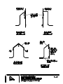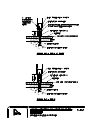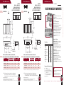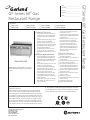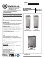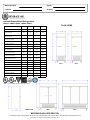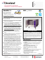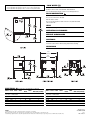
1
APPENDIX 1K: FOOD SERVICE EQUIPMENT Northern Health Lakes District Hospital and Health Care Centre Burns Lake, B.C PART 1 Section 11 40 03 FOODSERVICE - EQUIPMENT ITEMIZED SPECIFCATIONS Page 1 of 18 ITEMIZED EQUIPMENT NOTE: *L046 refers to the Specifier Identification System – it is not part of the model number and is strictly for specifier identification purposes by the manufacturer. It is the responsibility of the FEC to ensure all equipment meets or exceeds approval by authority having jurisdiction. FEC to obtain approval where required. It is the responsibility of the FEC to provide faucets that coordinate with the applicable sink locations, faucet spout to extend to center of sink. It is the responsibility of the FEC to ensure all drawers are to have drawer locks. It is the responsibility of the FEC to ensure all equipment is provided with components to ensure it can be installed to all applicable codes per authority having jurisdiction, including but not limited to SMACNA guidelines N.I.C. refers to equipment that is Not In Contract, not part of this bid package LEED Gold project – Energy efficiency is a priority. This project is a LEED project – the FEC is to note if equipment meets this standard or has Energy Star equivalent. All selected or proposed alternates are to meet or exceed this standard. It is the responsibility of the successful FEC to provide documentation to this affect. ITEM 1 Manufacturer: Size: Construction: Components: ITEM 2 Manufacturer: Size: Construction: Note: ITEM 3 Manufacturer: Model: Sizes: Approved Alternate: Accessories: WORK TABLE 1 REQUIRED Custom Fabricated Refer to plan and elevation; 760mm deep; refer to Standard Detail D-7.1 Stainless steel construction as specified Boxed edges Back and end splash up 8”/200mm and splayed, closed ends Bracing as required Bottom shelf with boxed edges, back up 25mm and hemmed 1 required drawer, as specified, with removable plastic liner, 6”/150mm deep OVERSHELVES 2 REQUIRED Custom Fabricated – wall mounted Refer to plan and elevation; refer to Standard Details D-4.1 Stainless steel construction as specified Shelf with boxed edges, back up and snapped, brackets as required Coordinate with site for wall backing locations SHELVING - DRY Metro Super Erecta Shelf *L046 1 required 1525 x 457mm 3 required 915 x 533mm 2 required 1220 x 533mm 2 required 1525 x 533mm Nexel equivalent Olympic equivalent Standard with 8 REQUIRED Northern Health Lakes District Hospital and Health Care Centre Burns Lake, B.C Note: ITEM 4 Manufacturer: Model: Approved Alternate: Unit: Size: Door: Components: Construction: Doors: Components: Services: Note: Section 11 40 03 FOODSERVICE - EQUIPMENT ITEMIZED SPECIFCATIONS Page 2 of 18 Epoxy coated finish 4 posts, 74P, per unit or common posts permitted where units are end to end, with floor plates 5 shelves per unit Verify sizes with room conditions, prior to ordering WALK-IN ASSEMBLY 1 REQUIRED Norbec Prefabricated Modular Walk-ins *L046 Kysor equivalent MasterBilt equivalent Cooler Cooler Approx. 2351 x 3072 x 2590 high Approx. 3450 x 3072 x 2590 high above finished floor above finished floor 1 required standard 1 required standard 1 required door light fixture 1 required door light fixture 2 required fluorescent light 1 required fluorescent light fixtures fixtures Standard as specified Full box unit; walls, ceiling and floors. Floor – Type A floor (integral insulated floor) as specified with locking screed; (floor to withstand concrete leveling topping and floor finish) 4”/100 mm minimum foamed in place urethane walls, ceilings and floors Interior and exposed exterior with white baked enamel finish, embossed finish texture Unexposed exterior with galvanized finish Exterior to have 250mm/10” wide stainless steel flush wall impact plate on exposed traffic areas Standard 36” x 78” (915 x 1981 mm) flush mounted doors, hinged as shown on the plan with, Magnetic gasket, positive latching, self-closing, safety release hardware, provision for padlock, cam lift hinges spring assisted and door snubber each door Threshold anti-condensate heater Stainless steel kickplate on interior and exterior of each door, 915 mm/36” high Door section to have incandescent type vapour-proof light, remote exterior mounted switch and conduit between switch and outlet box – wiring to be pre-wired and concealed, with automatic lighting control Walk-in flush mounted integral audio-visual digital alarms with mute and reset – Intelligence module, with automatic lighting control Internal panic button Manufacturer’s standard 1220mm/48” low temperature fluorescent light fixtures with bulbs or equivalent Closure panels to ceiling, if required – removable/vented for accessibility as required, finished ceiling, colour to match walk-in finish, ceiling height 2745 Trim strips to wall - colour to match walk-in finish Refer to Services Schedule FEC to verify clearances of finished ceiling height, finished floor to underside of ceiling work above to ensure proper installation access, fit, and operation of systems Northern Health Lakes District Hospital and Health Care Centre Burns Lake, B.C Section 11 40 03 FOODSERVICE - EQUIPMENT ITEMIZED SPECIFCATIONS Page 3 of 18 FEC to verify site access for panels FEC to verify site condition for finished ceiling and ceiling system ITEM 5 Manufacturer: Model: Accessories: Services: Custom Work: Note: ITEM 6 Manufacturer: Model: Accessories: REFRIGERATION SYSTEM - COOLER 1 REQUIRED Tecumseh/Russell or equivalent Manufacturers standard as specified *L046 Include all components as required and noted under applicable section of Foodservice Equipment Products with Water-cooled condensers as specified, sized for walk-ins and use, top mounted, extended 5 year warrantee, interior location; closed loop, provide 3way valve Design operating temperature 2oC (35oF) +/Unit coolers sized for walk-in and use and sized to balance with the condensing unit Evaporator to have drain pan with suitable drainpipe fitting, air defrost, extended 5 year warrantee Installation to include all piping, fittings, controls and accessories as required for a complete operational installation Label all refrigeration lines at unit by system Confirm location – unit to be mounted on top of box, confirm space and air circulation prior to installation, coordinate with applicable trade to ensure adequate air circulation for refrigeration systems– notify the consultant in writing if location is not suitable Ensure adequate service access to unit provided Refer to Services Schedule, verify with requirements Provide stainless steel protective channels around exposed evaporator piping within walk-in Electrical disconnect switch to be provided and installed by others (Electrical Division) per authority having jurisdiction REFRIGERATION SYSTEM - FREEZER 1 REQUIRED Tecumseh/Russell or equivalent Manufacturers standard as specified *L046 Include all components as required and noted under applicable section of Foodservice Equipment Products with Water-cooled condensers as specified, sized for walk-ins and use, top mounted, extended 5 year warrantee, interior location; closed loop, provide 3way valve Design operating temperature -24oC (-10oF) Unit cooler sized for walk-in and use and sized to balance with the condensing unit Evaporator to have drain pan with suitable drainpipe fitting, electric defrost, extended 5 year warrantee, verify that heat trace and insulation is installed for the full length of the evaporator drain line – heat trace must be operational prior to start-up of refrigeration system Coordinate with Mechanical Contractor for drain line heat coil wrap Defrost timers Installation to include all piping, fittings, controls and accessories as required for a complete operational installation Label all refrigeration lines at unit by system Confirm location – unit to be mounted on top of box, confirm space and air Northern Health Lakes District Hospital and Health Care Centre Burns Lake, B.C Services: Custom Work: Note: ITEM 7 Manufacturer: Model: Approved Alternate: Sizes: Accessories: Note: ITEM 8 Manufacturer: Model: Approved Alternate: Accessories: ITEM 9 Work: circulation prior to installation, coordinate with applicable trade to ensure adequate air circulation for refrigeration systems– notify the consultant in writing if location is not suitable Ensure adequate service access to unit provided. Refer to Services Schedule, verify with requirements Provide stainless steel protective channels around exposed evaporator piping within walk-in Electrical disconnect switch to be provided and installed by others (Electrical Division) per authority having jurisdiction SHELVING - WALK-IN DUNNAGE RACK 1 REQUIRED Metro Bow Tie HP2236PD *L046 Cambro equivalent Standard UTILITY CART - Existing 1 EXISTING Obtain unit from owner; clean and relocate as shown spare ITEM 11 PREP SINKS Construction: 10 REQUIRED Metro Metroseal 3 Super Adjustable Super Erecta Shelf *L046 Cambro equivalent Nexel equivalent Olympic equivalent 4 required 1220 x 450mm 2 required 915 x 450mm 4 required 1525 x 450mm Standard with Metroseal 3 finish or equivalent 4 posts, 63P, per unit 4 HD casters with donut bumpers each unit 4 shelves per unit Verify sizes with room conditions prior to ordering ITEM 10 Manufacturer: Size: Section 11 40 03 FOODSERVICE - EQUIPMENT ITEMIZED SPECIFCATIONS Page 4 of 18 1 REQUIRED Custom Fabricated Refer to plan and elevation; 750mm deep; refer to Standard Details D-7.1, D7.3 Stainless steel construction as specified Inverted boxed edges at sinks; sized to accommodate cutting boards over sinks; cutting boards sized to suit Backsplash up 8”/200mm and splayed, closed ends Bracing as required Open space for waste bin (and owner supplied ingredient bins) 2 required sinks approximately 410 x 510 x 305 mm deep, all welded, all coved Northern Health Lakes District Hospital and Health Care Centre Burns Lake, B.C Components: Services: ITEM 12 Manufacturer: Size: Construction: ITEM 13 Manufacturer: ITEM 14 Manufacturer: ITEM 15 Manufacturer: Size: Construction: Components: ITEM 16 Manufacturer: Size: Construction: Section 11 40 03 FOODSERVICE - EQUIPMENT ITEMIZED SPECIFCATIONS Page 5 of 18 Solid bottom shelf, mounted 10”/250mm AFF, with boxed edges, back up 1”/25mm and hemmed 2 required lever wastes without overflow as specified 1 required backsplash mounted faucet with swing spout as specified, center between sinks 2 required cutting boards as specified with finger holes at one end, with stainless steel mounting slides, mounted under drawer; sized to suit sinks 1 required drawer, as specified, with removable plastic liner, 6”/150mm deep Refer to Services Schedule OVERSHELF 3 REQUIRED Custom Fabricated– wall mounted Refer to plan and elevation; 300mm deep; refer to Standard Details D-4.1 Stainless steel construction as specified Edges boxed Brackets as required FOOD PROCESSOR - Existing 1 EXISTING Obtain unit from owner; clean and relocate as shown SLICER - Existing 1 EXISTING Obtain unit from owner; clean and relocate as shown MOBILE WORK TABLE 1 REQUIRED Custom Fabricated Refer to plan and elevation; 750mm deep; refer to Standard Detail D-7.2 Stainless steel construction as specified Boxed edges Solid bottom shelf, mounted 10”/250mm AFF, with boxed edges 1 required drawer, as specified, with removable plastic liner, 6”/150mm deep 127 mm diameter heavy duty casters, 4 with brakes corner casters with donut bumpers, 4 swivel, 2 fixed one end WORK TABLE 1 REQUIRED Custom Fabricated Refer to plan and elevation; 760mm deep; refer to Standard Details D-7.1, D7.3 Stainless steel table and cabinet construction as specified Boxed edges Back splash up 8”/200mm and splayed, closed ends and back Bracing as required Open section for waste bin Open in top to accept hot well unit 1 required sink approximately 355 x 410 x 250 mm deep, all welded, all coved Bottom shelf with boxed edges, back up 25mm and hemmed Integral stainless steel service chase, reinforced for equipment mounted on unit, access panels as required for access to service lines and shut-off valves Cabinet section to house hot wells and drawer; recessed drain valve to be Northern Health Lakes District Hospital and Health Care Centre Burns Lake, B.C Components: ITEM 17 Manufacturer: Model: Approved Alternate: Accessories: Services: Note: ITEM 18 Manufacturer: Model: Approved Alternate: Accessories: Services: Note: ITEM 19 Manufacturer: Model: Approved Alternate: Accessories: Section 11 40 03 FOODSERVICE - EQUIPMENT ITEMIZED SPECIFCATIONS Page 6 of 18 set back from leading edge of cabinet in accessible location for staff; stainless steel removable kickbase all sides; access panel to hub drain 1 required lift-up shelf with boxed edges – flush with counter top in up position 1 required utensil rack with hooks – service chase mounted 1 required lever waste without overflow as specified 1 required backsplash mounted faucet with swing spout as specified 1 required deck mounted fill faucet Fisher model 3110 or equivalent; hot & cold index button 2 required cutting boards as specified with stainless steel mounting slides 1 required drawer, as specified, with removable plastic liner, 6”/150mm deep Outlets as noted HOT WELL UNIT 1 REQUIRED Wells MOD-400TDM *L046 Delfield equivalent Vollrath equivalent Standard with Manifold drains; drain valve Remote infinite controls Refer to Services Schedule Drain valve to be mounted in easily accessible location – not at back of cabinet Unit to be mounted in service counter HAND SINK 1 REQUIRED Eagle HAS-10-FA-P *L046 Custom Fabricated Polar equivalent Standard with Foot operated; foot pedals Stainless steel pedestal with removable front cover for service access; floor and wall mounted Gooseneck faucet, p-trap and tail piece; basket drain Refer to Services Schedule FEC to ensure unit has applicable approvals – CSA Trim gap behind pedestal to service chase MIXER - 20QT Globe SP20 *L046 Hobart equivalent Berkel equivalent Standard with Stainless steel bowl Flat beater Stainless steel wire whip Spiral dough hook Cord and plug 1 REQUIRED Northern Health Lakes District Hospital and Health Care Centre Burns Lake, B.C Services: Note: ITEM 20 Manufacturer: ITEM 21 Manufacturer: Model: Approved Alternate: Accessories: ITEM 22 Manufacturer: Size: Construction: Services: Note: Section 11 40 03 FOODSERVICE - EQUIPMENT ITEMIZED SPECIFCATIONS Page 7 of 18 Refer to Services Schedule Electrical disconnect switch to be provided and installed by others (Electrical Division) per authority having jurisdiction TRAY CART - Existing 1 EXISTING Obtain unit from owner; clean and relocate as shown MIXER STAND 1 REQUIRED Piper 121-23-29TSS - modified *L046 Hatch equivalent Custom fabricated equivalent Standard with Foot plates (no casters) STAINLESS STEEL SERVICE WALL 1 REQUIRED Custom Fabricated Refer to plan, elevation and section; height to underside of finished ceiling + 50mm/2” into ceiling space; refer to Standard Detail D-19.2 Stainless steel construction as specified Floor to ceiling+, with horizontal center wall section between end chases, partial open section from floor to approximately 24”/610mm AFF, for access to services with full depth chases at ends, with stainless steel wall flashing at back (wall); end chases as required for services and support – equipment to fit tight to service wall where possible Service chases to floor for services each end Sides 20 gauge stainless steel spot welded to angle iron frame, with removable panels as required for access to services Angle iron frame to be primed with rustproof paint Quick disconnects, electrical outlets and plumbing connection points as noted under adjoining equipment to be fixed to angle iron frame within service wall with drop access at horizontal section – no exposed service lines – FEC to coordinate service runs with applicable trades Removable panels to be removable without the use of tools where easily accessible All shutoff valves to be concealed in chases and easily accessible, label valve locations Outlets as required Coordinate with service trades all line runs within horizontal section of service wall between service chases to equipment and access to service shut-off valves – no exposed/surface mounted services Section at ends to house shut-offs etc; swing doors with full length piano hinges; view window at fire suppression system Refer to Services Schedule Exhaust hood to be mounted on face of service wall – service wall is not to be within exhaust hood perimeter Coordinate with plumber for BFP locations – preference is above counter section within wall, if BFP are not located elsewhere --- FEC to verify prior to fabrication of service wall Northern Health Lakes District Hospital and Health Care Centre Burns Lake, B.C ITEM 23 Manufacturer: Model: Approved Alternate: Size: Construction: Accessories: Custom: Services: Note: ITEM 24 Manufacturer: Model: Approved Alternate: Accessories: EXHAUST HOOD Section 11 40 03 FOODSERVICE - EQUIPMENT ITEMIZED SPECIFCATIONS Page 8 of 18 1 REQUIRED Spring Air FD-B-MB-14.17/5-VE *L046 NOTE: refer to service schedule, site and mechanical engineers drawings for design cfm / duct sizing – alternates/equivalent to conform Halton equivalent Approximately 4350 x 1733mm – size as required to suit equipment coverage required per codes and AHJ Stainless steel construction as specified Boxed hood ULC listed Fabricated and installed to meet all governing codes and in compliance with latest ULC & NFPA-96 requirements and authority having jurisdiction TruFlow hood monitoring system – remote mounted in service wall Flush mounted vapour proof LED fixtures or equivalent Standard with One set of bulbs for each light fixture Grease cup to be mounted at outside end of hood – RH end Filter remover Hanging brackets – full length and continuous – seismically restrained Stainless steel closure panels to finished ceiling Refer to Services Schedule Refer to site for ceiling conditions prior to ordering and installation, for taper requirement per site conditions if required Coordinate interconnections of all components with Electrician and Fire Suppression Installer in connection with building systems and requirements of the AHJ FEC to provide all applicable certifications, letters of assurance, letters of compliance and other documents/drawings (including equivalent City of Vancouver K2 submittal requirements, if required by local AHJ) as requested by AHJ (Authority Having Jurisdiction) Test & startup by Certified Technician FIRE SUPPRESSION SYSTEM 1 REQUIRED Rangeguard Wet chemical Fabricated and installed to meet all governing codes and in compliance with latest regulations and authority having jurisdiction Kidde equivalent Acme equivalent Standard with Capacity for coverage of all cooking equipment under hoods, plenum and ducts as required by code and authority having jurisdiction Provide shut-off valves, contactors and solenoids as required by code for equipment under hood, coordinate installation of same with applicable subtrade 1 required local fire pull, confirm location with authorities having jurisdiction 1 required remote fire pull, confirm location with authorities having jurisdiction Conceal all piping where possible, exposed piping to be chrome plated, Northern Health Lakes District Hospital and Health Care Centre Burns Lake, B.C Additional: Note: ITEM 25 Manufacturer: Model: Accessories: Services: Additional Accessories: Custom work: Note: ITEM 26 Manufacturer: Model: Approved Alternate: Accessories: Services: Note: Section 11 40 03 FOODSERVICE - EQUIPMENT ITEMIZED SPECIFCATIONS Page 9 of 18 exposed horizontal piping not acceptable Activation of system by globe fusible links Integral with Exhaust Hood 1 required hand held ‘K’ class fire extinguisher; to be mounted in location as directed by the Authority having jurisdiction with 200mm x 279mm placard stating “Fire protection system to be activated prior to using fire extinguisher” FEC to provide all applicable certifications, letters of assurance, letters of compliance and other documents as requested by authority having jurisdiction for a complete certified operational system FEC to coordinate with the General Contractor as to the operation of the system as it relates to the building systems Coordinate interconnections of all components with Electrician in connection with building systems and requirements of the AHJ COMBI OVEN 1 REQUIRED Rational SCC62 *L046 Standard with Slow cooking capacities Two speed auto reversing convection fan Chicken grill rack each unit One extra container of cleaning solution Automatic washing system Wire shelves each unit Refer to Services Schedule, flexible connections Quick disconnect, as specified, for water service Filter system – Kleensteam/Everpure / Danamark or equivalent, size to suit unit and use – all components for a complete and operational system with one set of filters Custom fabricated stand to accommodate unit and provide space for hot holding cabinet under Verify site water quality prior to ordering Include for 1 day on-site training of staff Electrical disconnect switch to be provided and installed by others (Electrical Division) per authority having jurisdiction HOT HOLDING CABINET F.W.E. HLC-7 *L046 Alto Shaam equivalent Standard with Casters with locks – restraining cord Three (3) wire shelves; removable Stainless steel pan slides 3.5” casters; two rigid, two swivel Refer to Services Schedule Unit to fit under stand for Combi Oven 1 REQUIRED Northern Health Lakes District Hospital and Health Care Centre Burns Lake, B.C ITEM 27 Manufacturer: Model: Approved Alternate: Accessories: Services: Note: ITEM 28 Manufacturer: Model: Approved Alternate: Accessories: Services: ITEM 29 Manufacturer: Model: Approved Alternate: Accessories: Services: Additional Accessories: STEAMER Section 11 40 03 FOODSERVICE - EQUIPMENT ITEMIZED SPECIFCATIONS Page 10 of 18 1 REQUIRED Cleveland 22CET3.1 *L046 SteamCan equivalent Vulcan equivalent Standard with Stainless steel economy stand with pull-out shelf; pan slides Capacity: three full size insert pans Boilerless Automatic water fill and drain Refer to Services Schedule Confirm all plumbing and electrical connections are flexible Electrical disconnect switch to be provided and installed by others (Electrical Division) per authority having jurisdiction TILTING KETTLE 1 REQUIRED Cleveland KET-6-T *L046 SteamCan equivalent Vulcan equivalent Standard with Lift off cover Gallon and liter markings, measuring strips Hot and cold water faucet with bracket (DPK & FBKT) Stainless steel equipment stand with drain drawer & splash shield (ST-28) Refer to Services Schedule Electrical disconnect switch to be provided and installed by others (Electrical Division) per authority having jurisdiction RANGE 1 REQUIRED Garland GFE60-4G36CC *L046 US Range equivalent Vulcan equivalent Standard with Four (4) burners; 900mm/36” grill Two (2) convection ovens Electric spark ignition on all burners Snap action valves Rear gas connection Heavy-duty casters, front casters c/w brakes End caps and covers One additional oven rack Refer to Services Schedule Gas regulator and solenoid to be supplied to others for installation Quick disconnect – Dormont Supr-Safe flexible gas connector with Climfast QDV safety fitting and double Supr-swivels with restraining cord Gas regulator and solenoid, as required, to be supplied by FEC to others for installation Set of Posi-Set equipment positional brackets or equivalent; placed and Northern Health Lakes District Hospital and Health Care Centre Burns Lake, B.C Section 11 40 03 FOODSERVICE - EQUIPMENT ITEMIZED SPECIFCATIONS Page 11 of 18 secured as required ITEM 30 Manufacturer: Size: Construction: Components: ITEM 31 Manufacturer: Size: Construction: Components: FLOOR DRAIN PAN Custom Fabricated Refer to plan and site; 450 x 750 x 150mm deep 16 gauge stainless steel construction as specified Shallow depth units to suit site conditions All welded, refer to detail on Building Conditions drawing Stainless steel tail piece and waste, confirm location with site Slope to drain Pan to be flush with finished floor and, where required, to have "Z" bars welded to bottom for support 75mm (3”) diameter stainless steel pipe, caulked into trap – threaded or smooth to be verified with AHJ Grating to be fibergrate molded fiberglass, honeycomb or similar removable grate approved for foodservice areas or slot grating with slots no greater that 19mm (¾”) width space Grating is to be supplied with grit skid-resistant walking surface All cut or sanded surfaces are to be sealed with resin prior to installation Grating to sit on trough ledges and, where required, on stainless steel angles - to be removable in sections no greater than 450 x 1220mm (18” x 48”) Grating to be level with finished floor Pipe welded onto Component Hardware D43-X015 drain complete with lift out strainer basket D34-X016 or equivalent – verify code requirement for threaded pipe, provide threaded pipe if required by code MOBILE WORK TABLE spare ITEM 33 REACH-IN REFRIGERATOR - Existing ITEM 34 Manufacturer: Size: Construction: 1 REQUIRED Custom Fabricated Refer to plan and elevation; 750mm deep; refer to Standard Detail D-7.2 Stainless steel construction as specified Boxed edges Solid bottom shelf, mounted 10”/250mm AFF, with boxed edges 1 required drawer, as specified, with removable plastic liner, 6”/150mm deep 127 mm diameter heavy duty casters, 4 with brakes corner casters with donut bumpers, 4 swivel, 2 fixed one end ITEM 32 Manufacturer: 1 REQUIRED 1 EXISTING Obtain unit from owner; replace door gasket; inspect refrigeration system notify in writing if system requires service; clean and relocate as shown WORK COUNTER 1 REQUIRED Custom Fabricated Refer to plan and elevation; 760mm deep; refer to Standard Details D-7.1, D-7.3 Stainless steel construction as specified Boxed edges Northern Health Lakes District Hospital and Health Care Centre Burns Lake, B.C Components: ITEM 35 Manufacturer: Size: Construction: Note: Section 11 40 03 FOODSERVICE - EQUIPMENT ITEMIZED SPECIFCATIONS Page 12 of 18 Back and end splash up 8”/200mm and splayed, closed ends Bracing as required 1 required sink approximately 355 x 410 x 250 mm deep, all welded, all coved Bottom shelf with boxed edges, back up 25mm and hemmed 1 required basket waste without overflow as specified 1 required deck mounted faucet with swing spout as specified 1 required cutting boards as specified with stainless steel mounting slides 1 required drawer, as specified, with removable plastic liner, 250mm deep OVERSHELF 2 REQUIRED Custom Fabricated – wall mounted Refer to plan and elevation; refer to Standard Details D-4.1 One (1) shelf with section to accommodate microwave Stainless steel construction as specified Shelf with boxed edges, back up and snapped, brackets as required Coordinate with site for wall backing locations ITEM 36 COFFEE BREWER - N.I.C. - By Operator 1 BY OPERATOR ITEM 37 HOT WATER DISPENSER 1 REQUIRED Manufacturer: Model: Approved Alternate: Accessories: Services: Bunn-O-Matic HW-2 *L046 Curtis equivalent Standard with Cord and plug Refer to Services Schedule ITEM 38 JUICE DISPENSER - N.I.C. - By Operator 1 BY OPERATOR ITEM 39 TOASTER – pop-up 1 REQUIRED Manufacturer: Model: Approved Alternate: Accessories: Services: ITEM 40 Manufacturer: Model: Approved Alternate: Accessories: Services: Toasmaster TP430 *L046 Hatco equivalent Wells equivalent Standard with Cord and plug Refer to Services Schedule TOASTER Star QCS1-350 *L046 Toastmaster equivalent Standard with Cord and plug Refer to Services Schedule 1 REQUIRED Northern Health Lakes District Hospital and Health Care Centre Burns Lake, B.C ITEM 41 Manufacturer: Model: Approved Alternate: Accessories: Services: MICROWAVE OVEN Standard with Cord and plug Refer to Services Schedule spare ITEM 43 HAND SINK Services: Note: ITEM 44 Manufacturer: Size: Construction: Components: Services: 1 REQUIRED Panasonic NE-1064 *L046 ACP equivalent ITEM 42 Manufacturer: Model: Approved Alternate: Accessories: Section 11 40 03 FOODSERVICE - EQUIPMENT ITEMIZED SPECIFCATIONS Page 13 of 18 1 REQUIRED Eagle HAS-10-FA-P *L046 Custom Fabricated Polar equivalent Standard with Foot operated; foot pedals Stainless steel pedestal with removable front cover for service access; floor and wall mounted Gooseneck faucet, p-trap and tail piece; basket drain Refer to Services Schedule FEC to ensure unit has applicable approvals – CSA Trim gap behind pedestal to w SINK UNIT 1 REQUIRED Custom Fabricated Refer to plan and elevation; 760mm deep; refer to Standard Details D-10.5, D-10.10, D-10.12, D-10.15, D-10.16 Stainless steel construction as specified Edges up and rolled Backsplash splash up 250mm (10”) and splayed to wall, closed ends Bracing as required Drainboard slopes to sink Allow for space for waste cans 3 required sinks, approximately 670 x 515 x 355mm deep, all welded, rolled front to back, drain Reinforce sink & top for disposal and controls Edging into dishwasher at dishwasher Space for hose reel and mixing valve – set back valves from table edge Set required removable rack guides, non-vibrating (quiet), top flush with sink edge, at sinks Two (2) required sink covers; angle slides to hold covers Rack overshelf – verify mounting height with operator prior to mounting 2 required backsplash mounted faucets, 19mm Lever wastes Refer to Services Schedule Northern Health Lakes District Hospital and Health Care Centre Burns Lake, B.C ITEM 45 Manufacturer: Model: Approved Alternate: Accessories: Services: ITEM 46 Manufacturer: Model: Approved Alternate: Accessories: Services: Note: ITEM 47 Manufacturer: Size: Construction: Note: PRE-RINSE Section 11 40 03 FOODSERVICE - EQUIPMENT ITEMIZED SPECIFCATIONS Page 14 of 18 1 REQUIRED Fisher Model 13382 modified *L046 T & S equivalent Encore equivalent Standard with 48”/1220mm hose length Wall bracket Vacuum breaker In-line dual check valve Nipples Elbows Wrist style handles Spray valve with designed flow restrictor – Ultra-spray Valve #2949 Supply line – length as required Refer to Services Schedule DISPOSAL 1 REQUIRED In-Sink-Erator SS-100 *L046 Waste King equivalent Salvajor equivalent Standard with AS-101 Control Center Collar mount Solenoid valve Flow control valve Refer to Services Schedule Ensure adequate air circulation around unit for operation Electrical disconnect switch to be provided and installed by others (Electrical Division) per authority having jurisdiction OVERSHELF 1 REQUIRED Custom Fabricated Refer to plan and elevation; refer to Standard Detail D-10.13 Stainless steel construction as specified with brackets as required verify mounting height with operator prior to mounting ITEM 48 DETERGENT DISPENSER - N.I.C. - By Operator 1 BY OPERATOR ITEM 49 DISHWASHER - Existing 1 EXISTING Manufacturer: Model: Coordinate with GC for the disconnecting of the unit to ensure all components required to reinstall are retained; Obtain unit from Owner; inspect unit for any worn or damaged parts - notify in writing on any conditions requiring service; relocate as shown Hobart AM-15T Northern Health Lakes District Hospital and Health Care Centre Burns Lake, B.C ITEM 50 Manufacturer: Size: Construction: Services: Note: ITEM 51 Manufacturer: Size: Construction: ITEM 52 Overshelf: Size: Construction: Note: ITEM 53 Manufacturer: Model: Approved Alternate: Accessories: Services: Custom Work: CONDENSATE CANOPY Section 11 40 03 FOODSERVICE - EQUIPMENT ITEMIZED SPECIFCATIONS Page 15 of 18 1 REQUIRED Custom Fabricated Refer to plan and elevation, approximately 1100 x 1100mm Stainless steel construction with tapered top to duct Turned in boxed edge, shaped to catch condensation, sloped to drain at one corner 25 mm drain with NSF hose to counter top Hanging rods Stainless steel closure panels to ceiling Duct collar Refer to Services Schedule Unit mounted to provide steam capture from dishwasher and to clear dishwasher when doors open Coordinate/verify with Electrical division that condensate fan is operational when dishwasher is operational CLEAN DISH TABLE 1 REQUIRED Custom Fabricated Refer to plan and elevation; 760mm+/- deep; refer to Standard Detail D10.15 Stainless steel construction as specified Edges up and rolled Back and end splash up 250mm (10”) and splayed to wall, closed ends Slope top to dishwasher Perforated or slat (front to back) undershelf; boxed edges Edging into dishwasher at dishwasher OVERSHELF 1 REQUIRED Custom Fabricated – wall mounted Refer to plan and elevation; 300mm deep overshelf; refer to Standard Details D-4.1 Stainless steel construction as specified Edges boxed Brackets as required Coordinate with site for wall backing locations UNDERCOUNTER HOSE REEL 1 REQUIRED Fisher 2984 *L046 T & S equivalent Encore equivalent Standard with Vacuum breakers Check valves Mixing valves; table mounted, cross handles Spray valve with designed flow restrictor – Ultra-spray Valve #2949 Backflow prevention Refer to Services Schedule Stainless steel mounting bracket for mounting reel and mixing valves to Northern Health Lakes District Hospital and Health Care Centre Burns Lake, B.C Section 11 40 03 FOODSERVICE - EQUIPMENT ITEMIZED SPECIFCATIONS Page 16 of 18 table ITEM 54 Manufacturer: Size: Construction: Components: ITEM 55 Manufacturer: Model: Approved Alternate: Size: Accessories: FLOOR DRAIN PAN 1 REQUIRED Custom Fabricated Refer to plan and site; 300 x 300 x 150mm deep 16 gauge stainless steel construction as specified Shallow depth units to suit site conditions All welded, refer to detail on Building Conditions drawing Stainless steel tail piece and waste, confirm location with site Slope to drain Pan to be flush with finished floor and, where required, to have "Z" bars welded to bottom for support 75mm (3”) diameter stainless steel pipe, caulked into trap – threaded or smooth to be verified with AHJ Grating to be fibergrate molded fiberglass, honeycomb or similar removable grate approved for foodservice areas or slot grating with slots no greater that 19mm (¾”) width space Grating is to be supplied with grit skid-resistant walking surface All cut or sanded surfaces are to be sealed with resin prior to installation Grating to sit on trough ledges and, where required, on stainless steel angles - to be removable in sections no greater than 450 x 1220mm (18” x 48”) Grating to be level with finished floor Pipe welded onto Component Hardware D43-X015 drain complete with lift out strainer basket D34-X016 or equivalent – verify code requirement for threaded pipe, provide threaded pipe if required by code POT RACK 3 REQUIRED Metro Metroseal 3 Super Adjustable Super Erecta Shelf *L046 Cambro equivalent Nexel equivalent Olympic equivalent 457 x 1220 x 1371mm high Standard with Metroseal 3 finish 4 posts per unit 5”/127mm HD casters, all swivel, 2 with brakes each with donut bumpers per unit 4 shelves per unit ITEM 56 spare ITEM 57 COUNTER - N.I.C. - By Others 1 BY OTHERS ITEM 58 COFFEE BREWER - N.I.C. - By Operator 1 BY OPERATOR ITEM 59 COUNTER with sink - N.I.C. - By Others 1 BY OTHERS ITEM 60 REACH-IN REFRIGERATOR 1 REQUIRED Manufacturer: Beverage Air Northern Health Lakes District Hospital and Health Care Centre Burns Lake, B.C Model: Approved Alternate: Accessories: Services: Note: Section 11 40 03 FOODSERVICE - EQUIPMENT ITEMIZED SPECIFCATIONS Page 17 of 18 HBR23-1-G *L046 True equivalent Continental equivalent Standard with Casters; locks on door side Celsius reading digital thermometer Door hinging as shown on plan Full size glass door with lock Epoxy coated wire shelves - black One additional shelf Cord and plug Refer to Services Schedule Energy Star or equivalent ITEM 61 SERVICE COUNTER - N.I.C. - By Others 1 BY OTHERS ITEM 62 POS UNIT - N.I.C. - By Operator 1 BY OPERATOR ITEM 63 SOUP UNIT - Existing 1 EXISTING Manufacturer: Obtain unit from owner; clean and relocate as shown ITEM 64 COUNTER - N.I.C. - By Others 1 BY OTHERS ITEM 65 MICROWAVE OVEN - Existing 1 EXISTING Manufacturer: ITEM 66 Manufacturer: ITEM 67 Manufacturer: Size: Construction: Obtain unit from owner; clean and relocate as shown ICE & WATER DISPENSER - Existing 1 EXISTING Coordinate with GC for the disconnecting of the unit to ensure all components required to reinstall are retained; Obtain unit from owner; clean and relocate as shown CORNER GUARDS 4 REQUIRED Custom Fabricated Refer to Standard Detail D-26.1 16 ga stainless steel Mount to wall with countersunk screws and approved sealant; seal at top also Mount at top of wall base or 150mm AFF if no wall base present ITEM 68 WASTE CAN - N.I.C. - By Operator LOT BY OPERATOR ITEM 69 SOUP & TOWEL DISPENSER - N.I.C. - By Others LOT BY OTHERS ITEM 1000 Construction: Locations: Note: MISCELLANEOUS TRIM LOT REQUIRED 18 ga. stainless steel and ¾”/19 mm plywood with plastic laminate finish as required, noted and requested (this is over and above the specified standard requirements of a professional installation) Where required as directed by the Foodservice Consultant Allow for approximately 100sqft/9 sq m. of additional stainless steel for filler Northern Health Lakes District Hospital and Health Care Centre Burns Lake, B.C Section 11 40 03 FOODSERVICE - EQUIPMENT ITEMIZED SPECIFCATIONS Page 18 of 18 and trim and 10sqft/1 sq. m. of plywood with plastic laminate finish as directed by the Foodservice Consultant END OF SECTION Northern Health Lakes District Hospital and Health Care Centre Burns Lake, B.C Section 11 40 03 FOODSERVICE - EQUIPMENT BROCHURES NOTE: The following brochures are for information only and are not to be used for shop drawing submittal. It is the responsibility of the successful FEC to provide up to date and accurate brochures at submittal. Item No. ___________________________ SelfCooking Center® 62 E (6 x 18'' x 26''/12 x 12'' x 20'') Description: Unit for the automatic cooking of roasts, pan fries, poultry, fish, side dishes, potato products, egg dishes, desserts, bakery products and for automatic finishing. Combi-Steamer (Combi-Steamer Mode) for most cooking methods employed in the catering trade, with optional use of steam and hot air, separately, sequentially or combined. SelfCooking Control®- 9 operating modes: CombiSteamer mode - 3 operating modes: Options: • Left-hand hinged doors • Unit with mobile oven rack • RS 232 serial interface • RS 485 converter • Ethernet interface • Marine version (German Lloyd) • Security/Prision version • Integral fat drain • Can be connected to power optimization Sicotronic – others upon request. • Special voltages • Sous-vide core temperature probe • Menu pad • Lockable control panel, 2-step door latch Accessories: • Stands and base cabinets • Heat shield for left hand side panel • Grids, containers, trays, CombiFry® (frying baskets) • Superspike (poultry grids), CombiGrill® • Mobile plate rack • Transport trolley • Thermocover • UltraVent® condensation hood • UltraVent® condensation hood • Exhaust hood • CombiLink® software package • CombiCheck® service package • Combi-Duo kits for 2 units one on top of the other • Special Cleaner tablets and Care tablets • Adapters for sheet pans 18" x 26" Approvals: Features: • Clear control panel with pictograms • Rack monitoring with individual time programming of each rack for non-stop loading • Program memory for at least 350 cooking programs with up to 12 steps • Automatic cleaning and care system for cooking cabinet and steam generator works with normal water pressure • Automatic cleaning prompt that notes the cleaning stage and volume of chemicals • Care status is shown on the display • 6 cleaning stages for unsupervised cleaning and care, even overnight • Detergent and Care tabs (solid detergents) for optimum health protection • Maximum rack height 5 ¼ ft. (1.60 m) when original stand used • Sensor-controlled cabinet humidity, actual humidity in cabinet can be adjusted and requested on the control panel • 5 air speeds programmable • Humidifying function can be programmed with humidity values from 85 °F-500 °F (30 °C-260 °C) for Dry Heat and Combination • Core temperature probe with 6 measuring points and automatic correction if inserted incorrectly • Temperature probe integral with unit (cannot be lost) • Positioning aid for core temperature probe • Demand-related energy supply • Integral hand shower with infinitely variable regulation, automatic retracting system and integral water shut-off function • Highperformance fresh steam generator with automatic self-cleaning system prevents the development of lime-scale; softened water and regular de-scaling are tipically not required. • Level of scaling in the steam generator is monitored and displayed • Automatic, active rinsing and drainage of steam generator by pump • Lime-scale level of steam generator automatically sensed, automatic indication of when de-scaling is necessary, lime-scale level displayed at any time • Menu-guided de-scaling program • Integral, maintenance-free grease extraction system with no additional grease filter • Cool down function for fast cabinet fan cooling • Integral fan impeller brake • Rear-ventilated double glass doors, hinged inside pane for easy cleaning • Door handle with right/left and slam function • 2 door locking positions • Proximity door contact switch • Seamless hygienic cooking cabinet with rounded corners • Press-fit user-replaceable cabinet seal • Airflow-optimized cooking cabinet • Swivel air baffle with quick-release locks • Drip collector and door drip pan with continuous discharge to unit drain • Halogen cooking cabinet lighting with shock-proof CERAN glass • Microprocessorcontrolled cooking process • HACCP data 10-day memory and output via integral USB interface • Adjustable buzzer tone • Adjustable foreign languages display • Adjustable display contrast • Real time display • Free time selection with delayed start from 0-24 hours • Preselected starting time adjustable for time and date • Function Delta-T cooking • Temperature unit-adjustable in °C or °F • Half power setting • Automatic drain condensate cooling/quenching • Lengthwise loading for accessories • Hinging rack with additional rail for drip collector, rail distance 2 5/8" (68 mm), hinging rack swivel for easy cleaning • U-shaped rack rails with notched recesses for easy loading • All-round heat insulation • ServiceDiagnostic System with automatic service notices display • Safety temperature limiter for cabinet and steam generator • Hinged control panel allows front servicing and inspection • Operating and warning displays • Separate solenoid valves for normal and softened water • Height-adjustable feet • Material inside and out CrNi steel CNS 304 • 3 grids 20"x24" (2/1 GN) Consultant/Contractor: SelfCooking Center® 62 E (6 x 18'' x 26''/12 x 12'' x 20'') 1 Common water supply (cold water) 2 Water supply cold water 3 Water supply soft or hot water 4 Drain 5 Electrical connection 6 Equipotential bonding 7 Vent pipe 2" (50 mm) Minimum distance 2" (50 mm) Left side 20" recommended for servicing unit without the ability to move for servicing Measurements in mm (inches) Technical specification: Capacity (Steam pans): 12x12''x20'' Water drain: 2'' (50mm) O.D. (outside diameter) Non-Threaded stainless outlet Weight (Gross): Cubing packing: 46.9 cu.ft. (1.33 m³) Note: connect only to 2'' (50mm) diameter steam temperature resistant pipe Freight Class: 85, F.O.B. Connected load: 21 kW #AWG Wire size (140° F): ''Moist heat" connection: 18 kW Recommended breaker: Three Phase ''Dry heat" connection: 20 kW 208 V: 70 A Electrical connection: Three Phase 240 V: 80 A 208 V: 59 amps 440 V: 35 A 240 V: 68 amps 480 V: 40 A 440 V: 28 amps ** 480 V : 33 amps Notes: Dedicated circuit breaker required. Do not use fuses. Dedicated ground wire required. Weight (Net): 314 lbs (142.5 kg) Capacity (Full size sheet pans): 6x18''x26''* Capacity (GN-container/grids): 6 x 2/1 GN / 12 x 1/1 GN Loading for: 2/1, 1/1 GN Number of meals per day: 60-160 Width: 42 1/8'' (1,069 mm) Depth: 38 1/4'' (971 mm) Height: 29 3/4'' (757 mm) Water connection (pressure hose): 3/4'' NPS for 1/2'' pressure hose Note: Connect to drinking water only Water pressure (Flow pressure): 21.75 - 87 psi 335 lbs (152 kg) #3: 208/240 V #8: 440/480 V * With optional rack adapter Art.- 60.62.050 No.: ** Other voltages on request Installation Requirements, External Heat Source Proximity Each Combi-Steamer must be clear of all external sources of heat • Increased appliance temperature may cause damage to unit components • Installations must comply with all local electrical, plumbing and ventilation codes • RATIONAL recommends testing to determine if any harmful elements or conditions exist in the water • Consult owners manual, installation manual for additional installation requirements for specifics and details. Bidding specifications The RATIONAL unit cooks with hot air and pressureless steam – singular, sequentially and in combination. Cooking Modes 9 automatic modes for the automatic cooking of roasts, pan fries, poultry, fish, side dishes, potato products, egg dishes, desserts, bakery products and for automatic finishing. 3 Combi-Steamer modes for Steaming (85 °F-265 °F), Hot Air (85 °F-575 °F), Combi-Steaming (85 °F-575 °F). Unit shall be equipped with: High-performance fresh steam generator with automatic self-cleaning system prevents the development of lime-scale; soft water and regular de-scaling are not required. • Level of scaling in the steam generator is monitored and displayed • Clear control panel with pictograms • Core temperature probe with 6 measuring points • Sensor-controlled cabinet humidity • Automatic cleaning and care system for cooking cabinet and steam generator works with normal water pressure • Automatic cleaning prompt that notes the cleaning stage and volume of chemicals • Care status is shown on the display • 6 cleaning stages for unsupervised cleaning and care, even overnight • Detergent and care tabs (solid detergents) for optimum health protection • Seamless hygienic cooking cabinet with rounded corners • Integral, maintenance-free grease extraction system • Halogen cooking cabinet lighting • Automatic drain condensate cooling/quenching • Humidifying function • 5 air speeds programmable • Integral fan impeller brake • Rear-ventilated double glass doors • Door handle with right/left and slam function • Drip collector and door drip pan • Hinging rack with additional rail for drip collector • All-round heat insulation • Integral hand shower with infinitely variable regulation, automatic retracting • Separate solenoid valves for normal and soft water • HACCP data 10-day memory and output via integral USB interface. RATIONAL Cooking Systems 895 American Lane RATIONAL Canada 2410 Meadowpine Blvd., Suite Schaumburg IL 60173 USA Tel.:(847) 273-5000 Fax.:(847) 107 Mississauga, Ontario L5N 6S2 Canada Tél.: 905 755-9583 567 5777 Fax.: 905 567 2977 Visit us on the Internet: www.rational-online.com We reserve the right to make technical improvements PROJECT: ITEM NO.: 1/2 – 1-1/4 H.P. DISPOSER MODELS Heavy-duty disposer designed for continuous operation in restaurants, hotels, hospitals and cafeterias. Food waste including steak bones is quickly and efficiently removed with this labor-saving, self-cleaning, environmentally sound disposer. SPECIFICATIONS • Grind Chamber: Corrosion Resistant Stainless Steel • Mounting: 3/4" (19.1 mm) rubber mounting above grinding chamber isolates sound and eliminates vibration. Mounting is enclosed in chrome plated covers for sanitation and appearance. • Motor: 1/2 – 1-1/4 HP Induction Motor, 1725 RPM, totally enclosed to provide protection against outside moisture. Controlled power air flow cools motor for efficiency and longer life. Built-in thermal overload protection. • Cutting Elements: Stationary and rotating shredding elements made from cast nickel chrome alloy for long life and corrosion resistance, designed for reverse action grinding. • Main Bearings: Double-tapered Timken roller bearings provide a shock absorbing cushion. • Motor Seals: Triple lip seal protects motor from water damage. Secondary spring-loaded oil seal provides double protection against water and loss of grease. • Finish: All Stainless Steel and Chrome plated. Paint-free for lasting sanitation. • Warranty: 1 year full warranty from date of installation. • A Disposer Package Includes: 1 Mounting/Bowl Assembly, 1 Electrical Control, 1 Syphon Breaker, 1 Solenoid Valve, and 1 Flow Control Valve. The standard Flow Control Valve will be sent with the unit unless the optional valve is specified. MODEL & HORSEPOWER/ELECTRICAL REQUIREMENTS SS-50 1/2 H.P. 115/208-230V, 60 Hz, 1 Ph, 8.4/4.0/4.2 amps, UL 208-230/460V, 60 Hz, 3 Ph, 2.0/2.2/1.1 amps, UL 115/208-230V, 60 Hz, 1 Ph, 8.4/4.0/4.2 amps, CSA 208-230/460V, 60 Hz, 3 Ph, 2.0/2.2/1.1 amps, CSA SS-75 3/4 H.P. 115/208-230V, 60 Hz, 1 Ph, 10.0/4.2/5.0 amps, UL 208-230/460V, 60 Hz, 3 Ph, 2.5/3.0/1.5 amps, UL 115/208-230V, 60 Hz, 1 Ph, 10.4/4.3/5.0 amps, CSA 208-230/460V, 60 Hz, 3 Ph, 2.5/3.0/1.5 amps, CSA 115/230V, 50 Hz, 3 Ph, 7.7/3.7 amps 230/460V, 50 Hz, 3 Ph, 2.7/1.4 amps 380V, 50 Hz, 3 Ph, 1.1 amps SS-100 1 H.P. 115/208-230V, 60 Hz, 1 Ph, 11.6/5.1/5.7 amps, UL 208-230/460V, 60 Hz, 3 Ph, 2.2/3.0/1.5 amps, UL 115/208-230V, 60 Hz, 1 Ph, 11.6/5.1/5.7 amps, CSA 208-230/460V, 60 Hz, 3 Ph, 2.2/3.0/1.5 amps, CSA 120/208-240V, 60 Hz, 1 Ph, 11.6/5.1/5.7 amps, NOM 100/200-230V, 50/60 Hz, 1 Ph, 10.4/5.2/5.4 amps SS-125 1-1/4 H.P. 115/208-230V, 60 Hz, 1 Ph, 12.8/5.9/6.6 amps, UL 208-230/460V, 60 Hz, 3 Ph, 2.6/3.3/1.9 amps, UL 115/208-230V, 60 Hz, 1 Ph, 12.8/5.9/6.6 amps, CSA 208-230/460V, 60 Hz, 3 Ph, 2.6/3.3/1.9 amps, CSA NOTE: All amp ratings denote amp draw during a grind load. ELECTRICAL CONTROLS AS-101 Control Center “Aqua Saver” (Auto-Reversing) CC-101 Control Center (Auto-Reversing) CC-202 Control Center (Auto-Reversing) Manual Reverse Switch (Dual Direction) Manual Switch (Single Direction) Our products appear on The KCL CADalog CD-ROM based CAD Foodservice Symbol Library. More information is available from Kochman Consultants, Ltd. at www.kclcad.com. 4700 21st STREET RACINE, WI 53406 TEL: 800-845-8345 FAX: 262 554-3620 www.insinkerator.com InSinkErator is a division of Emerson Electric Co. The Emerson logo is a trademark and a service mark of Emerson Electric Co. InSinkErator ©2008 Printed in USA Form No. F307-09D-45-02 DISPOSER MOUNTING ASSEMBLIES (choose one) Bowl Mounts Collar Mounts Type A Sink Bowl Assembly: Includes bowl, water nozzle(s), bowl cover, splash baffle Type B Sink Bowl Assembly: Includes bowl, water nozzle(s), silver guard, splash baffle Type C Sink Bowl Assembly: Includes bowl, water nozzle(s), splash baffle Sink Bowl Assembly Size 12" (304.8 mm) with one adjustable water nozzle 15" (381.0 mm) with one adjustable water nozzle 18" (457.2 mm) with two adjustable water nozzles #5 Sink Flange Mounting Assemblies for 3-1/2" – 4" (88.9 mm – 101.6 mm) sink opening (support legs are recommended) #6 Collar Adaptor for welding into trough, provides 6-5/8" (168.3 mm) opening, includes splash baffle #7 Collar Adaptor for welding into sink, provides 6-5/8" (168.3 mm) opening, includes splash baffle and stopper DIMENSIONS IMPORTANT: Use dimension chart below for adaptor height in place of InSinkErator bowl sink height when mounting directly to a sink. X Y Z Bowl Sinks Flange O.D. X Work Table Hole Y Flange I.D. Z Height 12" (304.8 mm) 13-1/2" (342.9 mm) 12-1/4" (311.2 mm) 12" (304.8 mm) 6-1/2" (165.1 mm) 15" (381 mm) 16-1/2" (419.1 mm) 15-1/4" (387.4 mm) 15" (381.0 mm) 6-1/2" (165.1 mm) 18" (457.2 mm) 19-1/2" (495.3 mm) 18-1/4" (463.6 mm) 18" (457.2 mm) 6-1/2" (165.1 mm) Adaptors X Y Z Height No. 5 Fits Standard Sink Opening: 3-1/2" – 4" (88.9 mm – 101.6 mm) InSinkErator BOWL SINK 3-3/8" (85.7 mm) 2-3/4" (69.9 mm) No. 6 7-13/16" (198.4 mm) 6-7/8" (174.6 mm) 6-5/8" (168.3 mm) 1-3/16" (30.2 mm) No. 7 9-1/8" (231.8 mm) 7-7/8" (200.0 mm) 7-5/8" (193.7 mm) 2-1/16" (52.4 mm) NOTE: • Adaptors are available upon request for all competitor sink bowls or cones. • Please have sink bowl/cone type with the necessary dimensions when ordering adaptors. 6-1/2" (165.1 mm) 6-5/8" (168.3 mm) 17" (431.8 mm) 1/2-14 N.P.T. WATER INLET 7-11/16" (195.3 mm) 4-7/8" (123.8 mm) 6-3/8" (161.9 mm) 1-1/2" (38.1 mm) 6-13/16" (173.0 mm) EXTERNAL ELECTRICAL CONNECTIONS RECOMMENDED INSTALLATION RECOMMENDED WATER USAGE Standard Optional SS-50 3 GPM (11.4 LPM) N/A SS-75 3 GPM (11.4 LPM) N/A SS-100 5 GPM (18.9 LPM) 3 GPM (11.4 LPM) SS-125 5 GPM (18.9 LPM) 3 GPM (11.4 LPM) For additional information, see Foodservice Product Information Binder. Quick Link Directory Home Page Product Overview Specification Page: S4–2 PROJECT: MODEL: QUANTITY: ITEM NO: MOBILE HANDY LINE COMPARTMENTS For 12" x 20" and Gastro-Norm 1/1 Bulk Food Pans “HLC SERIES” HLC-8L Shown with Full-View Lexan Door and Edgemount Latch optional accessories. HLC-10 HLC-7 Natural radiant heat keeps foods oven fresh longer and prevent product dehydration and shrinkage. TM Handy Line Compartments Section 4 FWE’s natural convection heat/humidity system provides a soft radiant heat throughout the cabinet, perfect for holding pre-cooked foods for either short or prolonged periods of time. Serve appetizing food presentations from these units that help you produce consistent and better tasting foods. Hold and serve the best possible foods with FWE’s Mobile Pan Servers. Designed to accommodate 12" x 20" and GN 1/1 pans, these small holding cabinets do not require forced air movement. FWE’s unique pan slide racks are one piece die stamped stainless steel, providing greater hygiene and strength. The front edges are relieved for easy loading and the pair of racks are removable for easy cleaning. ◊ ◊ ◊ ◊ ◊ ◊ ◊ ◊ ◊ ◊ ◊ ◊ ◊ All stainless steel Welded construction - no rivets Tubular stainless steel welded base frame Heavy-duty polyurethane casters Recessed up-front controls Heavy-duty door hinges Positive close door latch Stainless steel lift handles Individually controlled compartments Hi-temp door gasket Fully insulated throughout Stainless steel pan slides Two year limited warranty UL ® C UL ® Stainless Steel made to serve you better NSF ® PROJECT: MODEL: QUANTITY: "W" MOBILE HANDY LINE COMPARTMENTS For 12" x 20" and GN 1/1 Bulk Food Pans ▲ ▲ SPECIFICATIONS: ITEM NO: PERFORMANCE VALUES ▲ T TOP "D" 190° 170° E 150° 130° M 110° TOP DOOR SWING: 20" ▼ 4' • • PREHEAT TIME ▲ P 70° 3' 2' RECOVERY 5 10 15 20 25 30 35 "H" 75°F to 170°F APPROX. 29 MIN. PREHEAT 1' RECOVERY 120°F to 170°F APPROX. 13 MIN. ▼ HLC-5 HLC-7 HLC-8 HLC-10 HLC-14 CAPACITIES OF 12'' x 20'' or GN 1/1 PANS [A] UNDER COUNTER MODELS MODEL NUMBER 2.625'' FIXED SPACINGS 66.7mm FIXED SPACINGS DEPTH 12'' x 20'' PANS DEPTH GN 1/1 PANS 2.5'' 4'' 6'' 65mm 100mm 150mm HLC-16 CLASS 100 OVERALL EXTERIOR DIMENSIONS IN. (mm) HIGH "H" DEEP "D" ELECTRICAL DATA WIDE * "W" 2 24.75'' (629) 30'' (762) 27.5'' 18.25'' (698) (464) 27.5'' 18.25'' (698) (464) 4 3 33.5'' (821) 27.5'' 18.25'' (698) (464) 10 4 4 14 6 4 24.75'' (629) 30'' (762) 27.5'' 35.25'' (698) (896) 27.5'' 35.25'' (698) (896) 6 33.5'' (821) 27.5'' 35.25'' (698) (896) HLC-5 5 2 2 5 2 2 HLC-7 7 3 2 7 3 HLC-8 8 4 3 8 HLC-10 10 4 4 HLC-14 14 6 4 NO. OF DOORS CASTER SIZE SHIP WT . LBS. (KG) HLC-5, HLC-7 HLC-10, HLC-14 HLC-8 HLC-16 CUBIC FEET (m3) VOLTS 120 120 500 1000 3.5" 105 (48) 115 (52) 7.19 (.20) 8.71 (.25) WATTS 3.5" 120 (54) 9.44 (.27) 13.88 (.39) 16.83 (.48) 18.23 (.52) 1 3.5" 1 1 AMPS 4.3 8.3 HERTZ 50/60 50/60 PHASE Single Single G HLC-16 16 8 6 16 8 2 3.5" 2 3.5" 165 (76) 180 (82) 3.5" 190 (86) 2 [A] Combinations of deep and shallow pans may be used with varying capacities. *Width Note: If omitting drop handles, subtract 1.25" (31 mm) from overall exterior width. • Pass-thru Door [add “P”] is available on all model sizes. Add 2.5" to depth dimension. • See-thru Lexan Door [add “L”] is available on all model sizes. CONSTRUCTION. Heliarc welded, single unit construction of stainless steel; 20-gauge polished exterior, 22-gauge stainless steel interior with easy-to-clean coved corners. Welded tubular base frame shall be 1" square, heavy gauge stainless steel tubing, with 10-gauge stainless steel reinforcing stress plates at corners. INSULATION. “Ultra-Guard” UG-26 high density fiberglass insulation throughout; top, back, bottom, sides and door(s). HANDLES. Heavy-duty stainless steel, side-mounted lift handles. DOORS AND LATCHES. Flush mounted, double pan, stainless steel doors shall have 1" thick fiberglass insulation. High temperature door gasket mounted on cabinet. Each door shall be equipped with flush-in-door stainless steel paddle latch; positive closing. Each door shall have two (2) heavy-duty lift-off hinges and allow 270° door swing. CASTERS. Maintenance free polyurethane tire casters in a configuration of two (2) rigid and two (2) swivel with brake. Casters shall have a reinforced yoke mounted to 10-gauge caster plate. The caster mounting plate shall be secured to a 10-gauge stainless steel reinforcing stress plate via welded in place stainless steel studs. The reinforcing stress plates shall be welded to the heavy gauge tubular frame of the unit. PAN SLIDES. Stainless steel racks shall be one piece die stamped channel-type pan slides at 2.625" (66.7 mm) spacings to accommodate either deep or shallow 12" x 20" or GN 1/1 pans (at varying capacities - see chart). Racks are removable without tools for cleaning. Racks shall lift off heavy-duty stainless steel supports. P.O. Box 1001 Crystal Lake, IL 60039 USA 800-222-4393; 815-459-7500 Fax: 815-459-7989 5-15P Manufacturing Facilities: 7900 S. Route 31 Crystal Lake, IL 60014 USA www.FWE.com [email protected] 5-15P Dedicated circuit. FWE Products are used by major companies world-wide. We can modify, design, or custom build equipment to fit your special requirements. HEATING SYSTEM/CONTROLS. Radiant heat system shall include an Incoloy nickel-chromium alloy heating element. Removable stainless steel baffled humidifier pan shall be provided. Controls shall be up-front, recessed and shall include a full range thermostat adjustable to actual temperature.Thermostat shall include temperature scale marked in ten degree increments (F/C) from 90° to 190°F (30° to 90°C). An operational range thermometer, power supply light and thermostat cycling light are also included. ELECTRICAL CHARACTERISTICS. 3 wire grounded 10 foot extension power cord and plug, rear mounted for safety. See electrical data chart above for amperage and receptacle configuration. Dedicated circuit. Food Warming Equipment Company, Inc. G NEMA PLUG Optional Accessories: ■ ■ ■ ■ ■ ■ ■ ■ ■ ■ ■ ■ ■ ■ ■ ■ ■ ■ ■ ■ ■ Electronic controls Digital thermometer 220 volt, 50/60 Hz, single phase CE complaint Heat retention battery See-thru Lexan door Pass-thru door Key locking door latch Magnetic latch Padlocking transport latch Left hand door hinging Security packages All swivel or larger casters Door edge trim Tubular handle Full extension bumper Corner bumpers Cold plate cartridge Custom pan slide spacing 6" floor legs 4" counter legs FWE products may be covered under one or more of the following U.S. patents: 288,299;238,300;3,952,609;4,192,991. All specifications subject to change without notice. © 10F Food Warming Equipment Company. Inc. W E L LS M A N U FA CT U R I N G W E L LS M A N U FA CT U R I N G R R STD.4 R E6070 DIMENSIONS: INCH (MM) MINIMUM CLEARANCE REQUIRED FROM UNIT TO THE NEAREST SURFACE. BACK SIDE BOTTOM FRONT 1 1 6 3/4 6 (25) (25) (171) (152) 14 (356) R R LISTED E6070 STD.4 M O D E LS MOD-500, MOD-500D M O D - 5 0 0 T, M O D - 5 0 0 T D MOD-500DM, MOD-500TDM B U I LT- I N M O D U L A R WA R M E R S R E6070 DIMENSIONS: INCH (MM) MOD-400 (1461) (57) (1816) • A one-year warranty against defects covers parts and labor. (57) Accessories / Options 9 3/4 1/2 INCH INTERNAL N.P.T. ’D’ MODELS ONLY 1 3/4 (44) 18 6 1/4 (457) (159) 35 (889) M O D - 4 0 0 , M O D - 4 0 0 D , M O D - 4 0 0 T, M O D - 4 0 0 T D , M O D - 4 0 0 D M A N D M O D - 4 0 0 T D M E L E C T R I C A L S P E C I F I C AT I O N S : AMPS POWER VOLTS WATTS AMPS PER LINE PHASE 3 L1 L2 L3 SINGLE PHASE SUPPLY CORD 1 3/4 1/2 INCH INTERNAL N.P.T. ’D’ MODELS ONLY (44) ’T’ MODELS M O D - 5 0 0 , M O D - 5 0 0 D , M O D - 5 0 0 T, M O D - 5 0 0 T D , M O D - 5 0 0 D M A N D M O D - 5 0 0 T D M E L E C T R I C A L S P E C I F I C AT I O N S : MODELS AMPS POWER VOLTS WATTS AMPS PER LINE PHASE 3 L1 L2 L3 SINGLE PHASE SUPPLY CORD MOD-400 208 3600 11.2 11.2 7.5 17.3 NONE MOD-500 208 4500 15.0 11.2 11.2 21.6 NONE MOD-400 240 4800 13.0 13.0 8.7 20.0 NONE MOD-500 240 6000 17.0 13.0 13.0 25.0 NONE MOD-400T 208 4960 14.5 14.5 9.8 23.8 NONE MOD-500T 208 6200 19.5 14.6 14.6 29.8 NONE MOD-400T 240 6600 17.8 17.8 11.3 27.5 NONE MOD-500T 240 8250 22.1 16.9 16.9 34.4 NONE All models with a ‘D' or 'DM' suffix have the same electrical specs as the standard MOD-400 or MOD-400T models. All models with a ‘D' or 'DM' suffix have the same electrical specs as the standard MOD-500 or MOD-500T models. NOTE: Specifications are subject to change without notice. See installation instruction sheet prior to installing the unit. This document is not for installation purposes. The Drain Manifold with Valve (1" internal N.P.T.) is supplied for DM & TDM models only. NOTE: Specifications are subject to change without notice. See installation instruction sheet prior to installing the unit. This document is not for installation purposes. The Drain Manifold with Valve (1" internal N.P.T.) is supplied for DM & TDM models only. 2 ERIK CIRCLE, PO BOX 280, VERDI, NV 89439 U.S.A. • USA PHONE: (775) 345-0444 • FAX: (775) 345-0569 FOR ORDERS ONLY: (888) 356-5362 • FAX: (800) 356-5142 • www.wellsbloomfield.com A SPECIALTY EQUIPMENT COMPANY • 2000 WELLS MANUFACTURING • PRINTED IN THE U.S.A. • 7/00 • REV(G) • PART NO. 37099 WELLS WELLS MANUFACTURING COMPANY 2 ERIK CIRCLE, PO BOX 280, VERDI, NV 89439 U.S.A. • USA PHONE: (775) 345-0444 • FAX: (775) 345-0569 FOR ORDERS ONLY: (888) 356-5362 • FAX: (800) 356-5142 • www.wellsbloomfield.com A SPECIALTY EQUIPMENT COMPANY • 2000 WELLS MANUFACTURING • PRINTED IN THE U.S.A. • 7/00 • REV(G) • PART NO. 37099 Wellslok Extension Kit, designed for installation in a variety of countertops up to 1” thick, refer to installation instructions, 22593 Specifications (248) (248) WELLS MANUFACTURING COMPANY • Each well is one-piece, deep-drawn, stainless steel construction for maximum strength and durability. 2 1/4 9 3/4 MODELS • Thermostat (T) models with higher wattage provide more accurate temperature control. • The MOD series Warmers are Underwriters Laboratories, Inc. LISTED and meet the National Sanitation Foundation and Canadian standards. 71 1/2 (889) • Fully insulated for greater efficiency. (600) 2 1/4 ’T’ MODELS • Designed for wet or dry operation. MOD-200TDM 23 5/8 57 1/2 35 • Wellslok allows for quick and easy installation in stainless steel countertops. (197) (600) (159) • Individual controls on each well give the warmers maximum versatility. 7 3/4 23 5/8 6 1/4 Features (356) (197) (457) BUILT-IN MODULAR WARMERS MINIMUM CLEARANCE REQUIRED FROM UNIT TO THE NEAREST SURFACE. BACK SIDE BOTTOM FRONT 1 1 6 3/4 6 (25) (25) (171) (152) 14 7 3/4 18 ITEM NO. Weights: MOD-100 series: Installed Shipping MOD-200 series: Installed Shipping MOD-300 series: Installed Shipping MOD-400 series: Installed Shipping MOD-500 series: Installed Shipping Lbs. KG 19 21 9 10 46 56 21 25 64 78 29 35 81 98 37 44 Individual drain connected to the manifold (DM), for all models except MOD-100 101 122 46 55 Individual thermostat and drain connected to the manifold(TDM), for all models except MOD-100 Drain Valve Extension Kit, extension from drain to counter front with remote handle, for use with “D” models only, excluding “DM” models, 20385 Drain Screen, 21709 Optional 72” Wiring, infinite or thermostatically controlled warmers, priced per well Individual drain (D), for all models Individual thermostat (T), for all models Explanation of Built-In Warmer Suffixes: D . . . . with drain Export T . . . . thermostatically controlled TD . . . . thermostatically controlled/with drain DM . . . with drain/connected to drain manifold/ infinite control TDM . . thermostatically controlled/with drain/ connected to drain manifold None . . infinite control The following models are available for export and meet the standards for CE: • MOD-100EUT, 220-240V, 1Ø, 1650 watts • MOD-100EUTD, 220-240V, 1Ø, 1650 watts WELLS WELLS R A I S I N G T H E S T A N D A R D BUILT-IN MODULAR WARMERS LISTED E6070 M O D E LS MOD-400, MOD-400D M O D - 4 0 0 T, M O D - 4 0 0 T D MOD-400DM, MOD-400TDM B U I LT- I N M O D U L A R WA R M E R S W E L LS M A N U FA CT U R I N G W E L LS M A N U FA CT U R I N G W E L LS M A N U FA CT U R I N G R R STD.4 R E6070 DIMENSIONS: INCH (MM) MINIMUM CLEARANCE REQUIRED FROM UNIT TO THE NEAREST SURFACE. BACK SIDE BOTTOM FRONT 1 1 6 3/4 6 (25) (25) (171) (152) 14 (356) R R LISTED E6070 STD.4 M O D E LS MOD-500, MOD-500D M O D - 5 0 0 T, M O D - 5 0 0 T D MOD-500DM, MOD-500TDM B U I LT- I N M O D U L A R WA R M E R S R E6070 DIMENSIONS: INCH (MM) MOD-400 (1461) (57) (1816) • A one-year warranty against defects covers parts and labor. (57) Accessories / Options 9 3/4 1/2 INCH INTERNAL N.P.T. ’D’ MODELS ONLY 1 3/4 (44) 18 6 1/4 (457) (159) 35 (889) M O D - 4 0 0 , M O D - 4 0 0 D , M O D - 4 0 0 T, M O D - 4 0 0 T D , M O D - 4 0 0 D M A N D M O D - 4 0 0 T D M E L E C T R I C A L S P E C I F I C AT I O N S : AMPS POWER VOLTS WATTS AMPS PER LINE PHASE 3 L1 L2 L3 SINGLE PHASE SUPPLY CORD 1 3/4 1/2 INCH INTERNAL N.P.T. ’D’ MODELS ONLY (44) ’T’ MODELS M O D - 5 0 0 , M O D - 5 0 0 D , M O D - 5 0 0 T, M O D - 5 0 0 T D , M O D - 5 0 0 D M A N D M O D - 5 0 0 T D M E L E C T R I C A L S P E C I F I C AT I O N S : MODELS AMPS POWER VOLTS WATTS AMPS PER LINE PHASE 3 L1 L2 L3 SINGLE PHASE SUPPLY CORD MOD-400 208 3600 11.2 11.2 7.5 17.3 NONE MOD-500 208 4500 15.0 11.2 11.2 21.6 NONE MOD-400 240 4800 13.0 13.0 8.7 20.0 NONE MOD-500 240 6000 17.0 13.0 13.0 25.0 NONE MOD-400T 208 4960 14.5 14.5 9.8 23.8 NONE MOD-500T 208 6200 19.5 14.6 14.6 29.8 NONE MOD-400T 240 6600 17.8 17.8 11.3 27.5 NONE MOD-500T 240 8250 22.1 16.9 16.9 34.4 NONE All models with a ‘D' or 'DM' suffix have the same electrical specs as the standard MOD-400 or MOD-400T models. All models with a ‘D' or 'DM' suffix have the same electrical specs as the standard MOD-500 or MOD-500T models. NOTE: Specifications are subject to change without notice. See installation instruction sheet prior to installing the unit. This document is not for installation purposes. The Drain Manifold with Valve (1" internal N.P.T.) is supplied for DM & TDM models only. NOTE: Specifications are subject to change without notice. See installation instruction sheet prior to installing the unit. This document is not for installation purposes. The Drain Manifold with Valve (1" internal N.P.T.) is supplied for DM & TDM models only. 2 ERIK CIRCLE, PO BOX 280, VERDI, NV 89439 U.S.A. • USA PHONE: (775) 689-5700 • FAX: (775) 689-5972 FOR ORDERS ONLY: (888) 356-5362 • FAX: (800) 356-5142 • www.wellsbloomfield.com A SPECIALTY EQUIPMENT COMPANY • 2000 WELLS MANUFACTURING • PRINTED IN THE U.S.A. • 7/00 • REV(G) • PART NO. 37099 WELLS WELLS MANUFACTURING COMPANY 2 ERIK CIRCLE, PO BOX 280, VERDI, NV 89439 U.S.A. • USA PHONE: (775) 345-0444 • FAX: (775) 345-0569 FOR ORDERS ONLY: (888) 356-5362 • FAX: (800) 356-5142 • www.wellsbloomfield.com A SPECIALTY EQUIPMENT COMPANY • 2000 WELLS MANUFACTURING • PRINTED IN THE U.S.A. • 7/00 • REV(G) • PART NO. 37099 Wellslok Extension Kit, designed for installation in a variety of countertops up to 1” thick, refer to installation instructions, 22593 Specifications (248) (248) WELLS MANUFACTURING COMPANY • Each well is one-piece, deep-drawn, stainless steel construction for maximum strength and durability. 2 1/4 9 3/4 MODELS • Thermostat (T) models with higher wattage provide more accurate temperature control. • The MOD series Warmers are Underwriters Laboratories, Inc. LISTED and meet the National Sanitation Foundation and Canadian standards. 71 1/2 (889) • Fully insulated for greater efficiency. (600) 2 1/4 ’T’ MODELS • Designed for wet or dry operation. MOD-200TDM 23 5/8 57 1/2 35 • Wellslok allows for quick and easy installation in stainless steel countertops. (197) (600) (159) • Individual controls on each well give the warmers maximum versatility. 7 3/4 23 5/8 6 1/4 Features (356) (197) (457) BUILT-IN MODULAR WARMERS MINIMUM CLEARANCE REQUIRED FROM UNIT TO THE NEAREST SURFACE. BACK SIDE BOTTOM FRONT 1 1 6 3/4 6 (25) (25) (171) (152) 14 7 3/4 18 ITEM NO. Weights: MOD-100 series: Installed Shipping MOD-200 series: Installed Shipping MOD-300 series: Installed Shipping MOD-400 series: Installed Shipping MOD-500 series: Installed Shipping Lbs. KG 19 21 9 10 46 56 21 25 64 78 29 35 81 98 37 44 Individual drain connected to the manifold (DM), for all models except MOD-100 101 122 46 55 Individual thermostat and drain connected to the manifold(TDM), for all models except MOD-100 Drain Valve Extension Kit, extension from drain to counter front with remote handle, for use with “D” models only, excluding “DM” models, 20385 Drain Screen, 21709 Optional 72” Wiring, infinite or thermostatically controlled warmers, priced per well Individual drain (D), for all models Individual thermostat (T), for all models Explanation of Built-In Warmer Suffixes: D . . . . with drain Export T . . . . thermostatically controlled TD . . . . thermostatically controlled/with drain DM . . . with drain/connected to drain manifold/ infinite control TDM . . thermostatically controlled/with drain/ connected to drain manifold None . . infinite control The following models are available for export and meet the standards for CE: • MOD-100EUT, 220-240V, 1Ø, 1650 watts • MOD-100EUTD, 220-240V, 1Ø, 1650 watts WELLS WELLS R A I S I N G T H E S T A N D A R D BUILT-IN MODULAR WARMERS LISTED E6070 M O D E LS MOD-400, MOD-400D M O D - 4 0 0 T, M O D - 4 0 0 T D MOD-400DM, MOD-400TDM B U I LT- I N M O D U L A R WA R M E R S W E L LS M A N U FA CT U R I N G Project ________________________________ ™ Cleveland Item __________________________________ ELECTRIC KETTLES Approval _______________________________ Quantity _______________________________ FCSI Section ____________________________ Date __________________________________ TABLE TYPE, ELECTRIC KETTLES TILTING, “SPLASH PROOF SERIES” SELF-CONTAINED, 2⁄3 STEAM JACKETED, 3, 6 or 12 GALLONS (11, 23 or 45 LITERS) MODELS: KET-3-T KET-12-T KET-6-T Cleveland Standard Features I Manual tilting, balanced design I Self-contained, easily installed - needs only an electrical hook-up I Steam jacket filled with treated water, venting and/or refilling is not required I Accurate, consistant solid state temperature controls (mechanical thermostate not as accurate) - less than ±1°C variance (ideal for simmering). Operating temperature range from 145° 260°F (63°C - 127°C) Control panel includes: • LED indicator for heat cycle • LED indicator for low water • Power ON/OFF switch • Adjustable temperature control dial I Water resistant controls, splash-proof construction I Large pouring lip for high capacity and chunky products. I Re-inforced rolled rim design prevents damage to kettle rim, eliminates "bar rim designs" I Welded-in heating elements, (holds vacuum better, won't leak or loose water) I Easily cleaned: kettle and all exterior surfaces are of type 304 stainless steel with an #4 finish I Rear mounted easy access pressure gauge and pressure relief valve to prevent tampering. Color coded easy to read pressure gauge with "green" and "vent air zone" I 50 psi steam jacket rating for higher cooking temperatures I 50 psi safety valve I Solid state water level control (no sight glass gauge to break or leak) I Splash proof element cover with a double gasket seal I Self locking marine type tilting mechanism prevents accidental spills. Balanced design makes it easy to tilt I Standard voltage is 208-240 volts, 60 Hz, 3 phase, 3 wire. Model KET-6 and KET-12 are field rewirable to single phase I Typical approvals include UL., CSA, CE, NSF and ASME Options & Accessories Ë Stainless Steel equipment stand with drain drawer and splash shield (ST-28) Ë Hot and cold (DPK) or cold only (SPK) water faucet with swing spout. Requires mounting bracket (FBKT) Ë 316 Stainless Steel kettle liner for high acid food products (316-G) Ë High wattages (HW) and special voltages (see back page) Ë Cooking Baskets (BS) Ë Food Strainers (FS) Ë Measuring Strips (MS) Ë Spray Hose (PRS-K) Ë Lift Off Cover (CL) Ë Kettle Markings (KM) Ë Protective Control Panel (PCE) Short Form Specifications Shall be CLEVELAND, electric kettle, Table Type, self-contained, tilting, Model KET - _____ - T; _____ gallons, _____ KW, _____ volt, _____ Hz, _____ - phase, 3 wire and single phase, 2 wire. 2/3 steam jacketed, type 304 Stainless Steel kettle and supports. Jacket rated at 50 psi with Safety Valve, Permanently filled Steam Jacket, Splash Proof Solid State Temperature (±1° C) and Safety Control System in plug-in Module including L.E.D. indicators. Marine Lock. Optional Lift Off Cover. 1333 East 179 St., Tel: 1-216-481-4900 Web Site: www.ClevelandRange.com Cleveland, Ohio, U.S.A. 44110 Fax: 1-216-481-3782 Email: [email protected] SECT. VIII 1 PAGE 0609 DIMENSIONS MODEL KET-3-T KET-6-T KET-12-T A B C D E F G H J K L M N Q R 20 1/4" 13 1/4" 6" 1 1/2" 14 1/2" 20" 18" 28 7/8" 12 7/8" NA 32" 11" 6" 15 1/2" 17" (514mm) (337mm) (152mm) (38mm) (368mm) (508mm) (457mm) (733mm) (327mm) (813mm) (279mm) (152mm) (394mm) (432mm) 24" 17" 6 1/2" 1 1/2" 16 1/2" 22 1/2" 18" 28 1/2" 15 1/2" 6" 34" 13 1/4" 6" 17 1/4" 17" (610mm) (432mm) (165mm) (38mm) (419mm) (572mm) (457mm) (724mm) (394mm) (152mm) (864mm) (337mm) (152mm) (438mm) (432mm) 27 1/2" 20" 7" 1 1/2" 19 1/8" 24 7/8" 18" 34" 16" 6" 38" 16 3/4" 6" 18" 17" (699mm) (508mm) (178mm) (38mm) (486mm) (632mm) (457mm) (864mm) (406mm) (152mm) (965mm) (425mm) (152mm) (457mm) (432mm) H C • CAPACITIES: (in 4 oz. servings, other sizes may be A calculated) 3 gallons / 11 liters ......... 96 servings 6 gallons / 23 liters ......... 192 servings 12 gallons / 45 liters ......... 352 servings B N M (I.D.) NOTE: SHOWN WITH OPTIONAL DOUBLE PANTRY FAUCET. CORD & PLUG SUPPLIED BY OTHERS H E F R C D J G K Q 14 1/2" (368mm) 2 3/32" (53mm) 14 1/2" (368mm) 14 1/2" (368mm) 2 3/32" (53mm) 2 3/32" (53mm) 1 1/2" (38mm) 1 15/16" (49mm) 7 9/32" (185mm) 12 1/2" (318mm) KET-3-T 12 1/2" (318mm) 5/16-18 THREADED BUSHINGS 18" (457mm) 5/16-18 THREADED BUSHINGS 7 3/8" (187mm) 12 1/2" (318mm) 5/16-18 THREADED BUSHINGS KET-6-T KET-12-T 18" (457mm) 18" (457mm) 10" (254mm) BASE MOUNTING DIAGRAMS (VIEW FROM BOTTOM OF BASE) STANDARD WATTAGE GALS. LITERS 3 11 6 23 12 45 KW 4.1 6.1 9.8 208V AMPS 1PH 19.7 29.5 47.2 240V 415V 480V AMPS AMPS AMPS AMPS AMPS AMPS 3PH KW 1PH 3PH KW 1PH 3PH KW 1 PH NA 5.4 22.7 NA NA NA NA NA NA 17.0 8.2 34.0 19.6 7.5 18.1 10.5 8.2 17.0 27.2 13.1 54.4 31.4 12.1 29.0 16.7 13.1 27.2 AMPS 3PH NA 9.8 15.7 WATER H C 3 ⁄8˝ O.D. copper tube or 1 ⁄2˝ N.P.T. pipe. When ordered with optional faucet. HIGH WATTAGE 208V AMPS AMPS GALS. LITERS KW 1PH 3PH KW 6 23 9.8 47.2 27.2 13.1 12 45 12.3 59.0 34.1 16.3 Consult factory for other voltages. 240V AMPS 1PH 54.4 68.1 415V 480V AMPS AMPS AMPS AMPS AMPS 3PH KW 1PH 3PH KW 1 PH 31.4 12.1 29.0 16.7 13.1 27.2 15.7 39.3 15.1 36.2 20.9 16.3 34.0 19.6 CLEARANCE RIGHT = 0˝ LEFT = 0˝ REAR = See “K” on chart above. NOTES: Cleveland Range reserves right of design improvement or modification, as warranted. Many regional, state and local codes exist and it is the responsibility of the owner and installer to comply with the codes. Cleveland Range equipment is built to comply with applicable standards for manufacturers. Included among those approval agencies are U.L., NSF, CGA, CSA, ETL and others. (NOT TO SCALE) SECT. PAGE 0609 Litho in U.S.A. VIII 2 Project Item # Quantity Model SP20 - 20 Quart Mixer Built into each mixer is the quality of workmanship and design synonymous with Globe. • • • • • • • • • • • • • • • Standard Accessories • • • • Optional Attachments/Accessories Powerful 1/2 HP custom built motor Three fixed speeds Gear driven, high torque transmission Heat-treated hardened steel alloy gears and shafts Permanently lubricated transmission Thermal overload protection Rigid cast iron body Removable stainless steel bowl guard with built in ingredient chute NSF approved enamel gray paint Front mounted controls 15 minute timer Industry standard #12 attachment hub Safety interlocked bowl guard and bowl lift Non-slip rubber feet Six foot cord and ground plug 20 quart stainless steel bowl Flat beater (aluminum) Stainless steel wire whip Spiral dough hook (aluminum) Slicer/shredder/grater for #12 hub Meat grinder for #12 hub Aileron (Wing) Whip 10 quart adapter kit Pastry knife Flat beater (stainless steel) Spiral dough hook (stainless steel) Mixer table with undershelf 20 Quart Mixer Standard Features GLOBE FOOD EQUIPMENT COMPANY SP20 20 Quart Mixer Standard Warranty • Two-years parts and one-year labor Featuring a Removable Bowl Guard • High-quality stainless steel removable bowl guard • Interlocking guard easy to attach and remove for easy cleaning • Dish machine safe Approved By: Date: www.globeslicers.com 2153 Dryden Rd. Dayton, OH 45439 Phone: 937-299-5493 Phone: 800-347-5423 Fax: 937-299-4147 SP20 GLOBE FOOD EQUIPMENT COMPANY 20 Quart Mixer Motor: 1/2 HP, grease packed ball bearing, air cooled, 115/60/1, 10 amps. Thermal overload protection (automatic reset). Finish: NSF approved enamel gray paint. Capacity: 20 quart (19 liter) bowl. Transmission: Fixed speed transmission is made of heat treated, hardened alloy, precision milled gears that operate the planetary action and provide high torque mixing power. The gears are packed in a long lasting grease, and all shafts are mounted in ball bearings. Removable Bowl Guard: Made of high-quality stainless steel. Interlocking guard is easy to attach and reattach for easy cleaning in a sink or dishwasher. When guard is open or not properly installed, the mixer will not operate. Safety Interlocks: The bowl guard and bowl lift lever are interlocked. The mixer will automatically shut down when the guard is opened or the bowl is lowered. Agitator Speeds (RPMs): Low 104 Intermediate 194 High 353 Attachment Speeds (RPMs): Low 59 Intermediate 110 High 201 SP20 Specifications Standard Equipment: Standard equipment includes a 20 quart #304 series stainless steel bowl, aluminum spiral dough hook, stainless steel wire whip, aluminum flat beater, removable stainless steel bowl guard with built in ingredient chute, 15 minute timer and #12 attachment hub. A sturdy hand lever on the body column raises and lowers the bowl as well as locking in place at the top and bottom positions. Cord: 6 ft. flexible three wire cord and ground plug. Dimensions: Foot Print = 18.7” x 16.7” (47.5cm x 42.4cm) Overall Length = 21.9” (55.6cm) Overall Width = 22.4” (56.9cm) Overall Height = 34.5” (87.6cm) Shipping Information: Freight Class: 85 Net Weight: 199 lbs. (80 kg) Shipping Weight: 270 lbs. (122.5kg) Shipping Dimensions: 32”W x 40”D x 48”H (81.3cm x 101.6cm x 121.9cm) Cartons are affixed to a skid (pallet). The weight and dimensions of this skid are included above and may vary from shipment to shipment. Optional Accessories: XXACC10-20 Adapter Kit (includes a 10 quart bowl, wire whip, dough hook, flat beater, and bowl adapter to adapt 20 quart mixer to a 10 quart capacity) XXACC12-20 Adapter Kit (includes a 12 quart bowl, wire whip, dough hook, flat beater, and bowl adapter to adapt 20 quart mixer to a 12 quart capacity) XXAWHIP-20 XXSCRP-20 XXPASTRY-20 XXBEAT-20SS XXHOOK-20SS Aileron (Wing) Whip Bowl Scraper Pastry Knife Stainless Steel Flat Beater Stainless Steel Spiral Dough Hook XTABLE Mixer Table with Undershelf (stainless steel top with galvanized steel undershelf and legs) 30”W x 24”D x 24”H (76.2cm x 61cm x 61cm) Optional Attachments: XMCA-SS Meat Grinder Assembly (Polished stainless steel cylinder, worm gear, ring, and pan. Includes knife, 3/16” plate, stainless steel pan and pusher.) Chopper Plate Sizes Available: CP02-12 1/16” (2mm) CP04-12 5/32” (4mm) CP05-12 3/16” (5mm) CP06-12 1/4” (6mm) CP08-12 5/16” (8mm) CP10-12 3/8” (10mm) CP12-12 1/2” (12mm) CP14-12 9/16” (14mm) CP16-12 5/8” (16mm) CP18-12 11/16” (18mm) CP00-12 Stuffing Plate XST12 1/2” stuffing tube (sheep) XST34 3/4” stuffing tube (hog) XVSGH 9” Slicer/Shredder/Grater Housing Only (no plates included-must select from plates below) XASP Adjustable slicing plate XPH Plate holder - *only 1 required GLOBE FOOD EQUIPMENT COMPANY www.globeslicers.com 2153 Dryden Rd. Dayton, OH 45439 Phone: 937-299-5493 Phone: 800-347-5423 Fax: 937-299-4147 Specifications are subject to change without notice. Printed in U.S.A. 04-2010 Shredding/Grating Plates: XSP332* 3/32” (2.3mm) XSP316* 3/16” (4.7mm) XSP14* 1/4” (6.3mm) XSP516* 5/16” (7.9mm) XSP12* 1/2” (12.7mm) XGP* Grating plate Quantity:_ __________________________ Project:_____________________________ GF Series 60" Gas Restaurant Range Approval:___________________________ Date:_______________________________ Models: GF60-10RR GF60-8G12RR GF60-6G24RR GF60-4G36RR GFE60-10RR GFE60-8G12RR GFE60-6G24RR GFE60-4G36RR Standard Features: • Flame failure protection: all burners • Spark ignition on all concealed burners (open top burners manual ignition) • Large 27" (686mm) work top surface • Stainless steel front and sides • Stainless steel 5" (127mm) plate rail • Stainless steel low profile back guard • 12" (305mm) section stamped drip trays w/ dimpled bottom • 6" (152mm) adj. stainless steel legs • Large easy-to-use control knobs • Gas regulator 1" NPT rear gas connection Standard on Applicable Models: Model GF60-10RR NOTE: Ranges supplied with casters must be installed with an approved restraining device. • Electric spark ignition on all burners, requiring single phase 115V 60Hz or 240V 50Hz (specify) prefix GFE models • Ergonomic split cast iron top ring grates • 26,000 Btuh/7.61 kW 2 piece cast iron Starfire- Pro open top burner • 5/8 (15mm) thick steel griddle plate w/manual hi/lo valve control, 23" (584mm) working depth surface, standard on right, optional on left • 4-1/4" (108mm) wide grease trough • 18,000 Btuh/5.27 kW cast iron "H" style griddle burner per 12"(305mm) width of griddle • Strong, keep-cool oven door handle • 38,000 Btuh/ 11.13 kW cast iron "H" style oven burner Specifications: Gas restaurant series range with large capacity (standard) oven. 59 1/16" (1500mm) wide and 27 1/4" (686mm) deep work top surfaces. Total flame failure protection for all burners. Stainless steel front, sides and 5" (127mm) wide front rail. 6" (152mm) legs with adjustable feet. Ten Starfire-Pro 2 piece, 26.000 Btuh/7.61 kW, cast open burners set in split cast iron ergonomic grates. Griddle or optional hot top with cast iron "H" style burners. Porcelain oven interior with ribbed oven bottom and door. "Keep cool" oven door handle. Heavy cast iron Garland Commercial Ranges Ltd 1177 Kamato Road, Mississauga, Ontario L4W 1X4 CANADA Phone: 905-624-0260 Fax: 905-624-5669 • Snap action modulating oven thermostat low to 500° F • Large porcelain oven interior, fits standard sheet pans in both directions for standard ovens • Nickel plated oven rack and 3-position removable oven rack guide • Convection oven w/3 nickel plated oven racks and removable rack guides in lieu of standard oven w/ 1/3HP 120v 60 Hz single phase fan motor; change suffix RR to CR (1) or CC (2) convection ovens, CR ovens standard on right Optional Features: Convection oven motor 240V 50/60 Hz single phase. Grooved griddle in 1/2 or full plate section widths Snap action modulating griddle control 175 to 475 F (79 to 218 C) Hot top 12" (305mm) plate in lieu of two open burners, manual valve controlled w/18,000 Btuh/5.27 kW cast iron "H" burner standard on left side Stainless steel backguard, w/removable stainless shelf Stainless steel back panels for backguards or range Additional oven racks 6” (152mm) levelling swivel casters (4), w/front locking Flanged deck mount legs Celsius temperature dials "H" 38,000 Btuh/11.13 kW (natural gas) oven burner controlled by even bake, fast recovery snap action modulating oven thermostat. Available with convection or standard oven bases. TM GF Series 60" Gas Restaurant Range Item: _______________________________ Total BTU/Hr Natural Gas Description Shipping Information Lbs. Kg Cu. Ft. GF60-10RR Ten Open Burners w/ Two Standard Ovens 336,000 726 329 79 GF60-8G12RR 12" Griddle, Eight Open Burners w/ Two Standard Ovens 302,000 756 343 79 GF60-6G24RR 24" Griddle, Six Open Burners w/Two Standard Ovens 268,000 775 342 79 GF60-4G36RR 36" Griddle, Four Open Burners w/Two Standard Ovens 234,000 826 375 79 Includes GFE models with electric spark ignition Also available with convection oven change RR to RC for one convection oven or CC for two convection ovens 1 Width Depth2 In (mm) In (mm) 59-1/16 (1500) 34-1/2 (876) Height Oven Interior-in (mm) w/ 3 LPBG In (mm) Height Depth4 Width 45-3/8 (1153) 13 (330) 26 (660) Combustible Wall Clearance-In (mm) 26-1/4 (667) Entry Clearances In (mm) Manifold Operating Pressure Sides Rear Crated Uncrated Natural Propane 14 (356) 6 (152) 37 (940) 36-1/2 (927) 4.5" WC 11 mbar 10.0" WC 25 mbar 2 Convection oven base models add 3 7/8” (98mm) to the depth of the unit. 3 LPBG = Low Profile Backguard 4 Convection oven depth 22" (559mm) Gas input ratings shown for installations up to 2000 ft.(610m) Burner Ratings (BTU/Hr/kW) above sea level. Please specify altitudes over 2000 ft. Griddle/ Standard Oven Gas Type Open Top This product is not approved for residential use. Hot Top or Convection 6' POWER CORD (FOR OPTIONAL CONVECTION MOTOR) 34-1/2" [876mm] 3-1/2" [89mm] 2-1/4" [57mm] 27-1/4" [692mm] Natural 26,000/7.61 18,000/5.27 38,000/11.13 Propane 26,000/7.61 18,000/5.27 32,000/9.38 All 115V, 60Hz, 1 phase GFE models are supplied with a 6' (1829mm) cord and plug (NEMA-5-15P), 240V 50/60 Hz. 1 phase, 1.8 amps are not supplied with cord and plug and must be direct connect. Convection oven models draw 3.5 amps, standard GFE models draw 0.2 amps for the ignition system; 240V systems without the convection motor are 0.1 amps. 5" [127mm] 1-1/2" [38mm] 1" N.P.T. REAR GAS INLET 59-1/16" [1500mm] 23-1/4" [590mm] 12-1/8" [307mm] 9-3/8" [238mm] 18-3/8" [466mm] 6" [152mm] 51" [1296mm] STD BACKGUARD W/HIGH SHELF (OPTIONAL) 39-3/8" [1000mm] LOW PROFILE BACKGUARD 30" [763mm] 13-7/8" [352mm] ADD WHEN DOOR OPEN 1" [25mm] GAS INLET 31-1/8" [791mm] 3-7/8" [98mm] ADD FOR CONVECTION OVEN Form# GF60 (08/05/10) Garland Commercial Ranges Ltd 1177 Kamato Road, Mississauga, Ontario L4W 1X4 CANADA Phone: 905-624-0260 Fax: 905-624-5669 G Series 60" Gas Restaurant Range Model Number1 Item No. Quantity 3779 Champion Blvd., Winston-Salem, NC 27105 1-888-845-9800 Fax# 1-336-245-6453 http://www.Beverage-Air.com BOTTOM MOUNTED REACH-IN REFRIGERATORS Horizon Series Solid Doors and Glass Doors Commercial Refrigeration Equipment General Specification MODEL: HBR23-1 / HBR23-1-G HBR27-1 / HBR27-1-G HBR49-1 / HBR49-1-G HBR72-1 / HBR72-1-G 18 Month Parts/Labor Warranty—5 Year Compressor CABINET CONSTRUCTION Exterior—Stainless steel interior and exterior standard. Insulation—foamed-in-place CFC and HCFC-free polyurethane insulation. One-piece grille allows easy removal/installation for preventative maintenance. ELECTRONIC CONTROL Electronic thermostat provides a digital display of cabinet temperatures, which includes status indicators and key pad for any necessary temperature adjustments. REFRIGERATION SYSTEM Bottom mount balanced refrigeration system for better ergonomics. Automatic condensate evaporation system for energy efficiency. Forced-air system ensures uniform distribution of airflow throughout the entire cabinet for even product temperatures; maintains product temperatures between 36 - 38°F. Self-contained refrigeration system uses environmentally friendly (CFC and HCFC-free) R134A refrigerant. HBR23-1 HBR27-1 (SHOWN WITH FULL SOLID DOOR) Full Glass Door model available (SHOWN WITH FULL SOLID DOOR) Full Glass Door model available DOORS Choose from full solid door or full glass door configuration. Glass door units only: Energy efficient, “Low-E”, double pane thermal glass. Anti-microbial door handles and door locks are standard. Spring-loaded hinges standard. Positive seal self-closing door(s) with 120° stay open feature. Plug-in magnetic door gaskets of one piece construction, removable without tools for ease of cleaning. SHELVING Three (3) heavy duty epoxy coated wire shelves per section standard. Four (4) shelf clips included per shelf (field installed). Shelves are adjustable in ½” increments. MODEL FEATURES Incandescent interior lighting—solid door units. Fluorescent interior lighting—glass door units. LED lighting option—glass door units only. 6” heavy-duty casters included, two with brakes standard. 6” legs optional. Pre-wired plug for 115/60/1 phase. Epoxy coated evaporator prevents corrosion. ENERGY STAR® Qualified UL-EPH and CUL for open food product. 3” casters or HBR49-1 (SHOWN WITH FULL SOLID DOOR) Full Glass Door model available Available From: *Note: Not all markings may apply to all model variations. Model Specified Store# Location Quantity Horizon Bottom Mount Refrigerators Models: HBR23, HBR27, HBR49, HBR72 MODEL HBR23 HBR27 HBR49 HBR72 27 1/4” 692 30” 762 52” 1321 75” 1905 33 3/4” / 857 33 3/4” / 857 33 3/4” / 857 33 3/4” / 857 78” / 1981 78” / 1981 78” / 1981 78” / 1981 1 1 2 3 60” 60” 60” 60” NET Capacity (cubic ft.) NET Capacity (Liters) 23 651 27 765 49 1388 72 2039 Internal Length Overall (inches) Internal Length Overall (mm) 24” 610 27” 686 49” 1245 72” 1829 Internal Depth Overall (inches) Internal Depth Overall (mm) 28 1/2” 724 28 1/2” 724 28 1/2” 724 28 1/2” 724 Internal Height Overall—(inches) Internal Height Overall—(mm) 61 3/4” 1569 61 3/4” 1569 61 3/4” 1569 61 3/4” 1569 3 3 6 9 5.8 A 5.8 A 8.8 A 9.9 A 1/3 1/3 1/3 1/2 Gross Weight (Crated lbs) 300 373 530 715 Gross Weight (Crated kg) 136 169 240 324 PLAN VIEWS EXTERNAL DIMENSIONAL DATA Length Overall (inches) Length Overall (mm) Depth Overall (inches) / (mm) Add 1 3/4” for handle Height Overall— (inches) / (mm) Add 6” for legs or casters Number of doors Depth with Door Open 90 o INTERNAL DIMENSIONAL DATA Number of shelves ELECTRICAL DATA Full Load Amperes 115/60/1 HBR23 HBR27 REFRIGERATION DATA Horsepower WEIGHT DATA Note: Not all markings may apply to all model variations. COMMON END HBR49 HBR72 BEVERAGE-AIR® CORPORATION 3779 Champion Blvd. • Winston-Salem, NC 27105 USA • (336) 245-6400 • Fax (336) 245-6453 • (888) 845-9800 • www.beverage-air.com Specifications are subject to change without prior notice. 04/11 Project ________________________________ ™ Cleveland Item __________________________________ HIGH EFFICIENCY BOILERLESS STEAMCHEF™ CONVECTION STEAMERS Approval _______________________________ Quantity _______________________________ FCSI Section ____________________________ Boilerless Convection Steamer, Automatic Water Fill & Drain, 12 kW Boiler-Free Counter Type Design Technology By Cleveland Standard Features I I I I I I I I I I I I Cooking capacity for up to three 12" x 20" x 2.5" deep steam table pans (1/1 G/N, 65 mm). High-speed electric convection steamer with open style 1.0 gallon water reservoir located at the bottom of the cooking compartment for easy access and maintenance. Fan forced convection steam with patented KleanShield TM cooking compartment design. KleanShield TM collects and removes condensate waste from the cooking compartment. This keeps the compartment clean, safe from impurities and easy to maintain. Eliminates foaming and avoids contamination of the reservoir water. Automatic water level controls, fills when main power switch is turned ON, Low Water and High Water probes inside cooking compartment maintains water levels during cooking, eliminating the need to manually refill and monitor water level during cooking. Additional Safety Overflow Standpipe. 193˚ preheat and standby temperature. High Temperature Automatic Safety Shut-off. Steam and Fan Shut Off Control when compartment door is opened. 12 kW electric heating element encased in a solid aluminum block for fast and ultra efficient heat transfer. Element never needs deliming because it is not immersed in water. Exclusive SureCook Compartment Controls improves cooking speed and accuracy. New energy saving design reduces water and electric usage. On-demand power control for faster heat up and recovery. Energy saving Standby Feature when not in use. The SureCook timer automatically adjusts the cooking time with the volume of product being cooked, eliminating guesswork on when the product is finished. Includes a 60-Minute Electro-Mechanical Timer, LED Indicator Lights for SureCook Cycle, Power On and Reset. Timed and Manual Bypass Switch for constant steaming. Exclusive SteamChef TM Automatic Drain Control. Generator Drains when main power is turned OFF via 1/2" ball valve with micro switch circuitry. Simple 1 1/4" NPT drain connection required with water saving cold water condenser and 3 minute rinse feature. Left Hand Door Hinging: Compartment Doors hinged on the left, controls on the right. Exclusive, durable 14 gauge stainless steel compartment door and latch withstands abuse and heavy wear. Two piece compartment door with free floating inner door is self adjustable and prevents leaks. Reversible door gasket doubles the life of the gasket. Heavy-duty 4" (102mm) Skid Resistant Adjustable Legs with Flanged Feet. Meets agency codes: specifically UL and CUL listed, classified to NSF#4 and Energy Star. Short Form Specifications Shall be a Cleveland SteamChef TM 3, model 22CET3.1, one compartment high-speed electric convection steamer. ____ volt, ____ phase. Standard with SureCook Compartment Controls, 60-minute electro-mechanical timer with load compensating feature. Capacity for three 2.5" (1/1 G/N, 65 mm) full size steam table pans. 12kW electric heating elements in aluminum blocks. Includes 1/2" ball valve style automatic drain. Automatic water level controls. Heavy-duty 14 gauge stainless steel cooking compartment door and latch. KleanShieldTM clean cavity protection. 4" Adjustable Legs Options & Accessories Ë 34" (864mm) High Stainless Steel Economy Stand, for one 22CET3.1 (UniStand34) Ë 25" (610mm) High Stainless Steel Stacking Stand (UniStand25), for mounting two stacked 22CET3.1, includes 2" Stainless Steel Mounting Spacer Ë POSK Pull-Out Shelf Kit for UniStands (P/N 111724) Ë URK Pan Rack Kit UniStands (P/N 111726) Ë Right Hand Door Hinging, Controls on Left (DHR) Ë ON/OFF Compartment control only, no timer (MC) Ë Electronic Timer Ë 5 Foot (1524mm) FDA Approved National Hose Thread style water connection kit (garden hose thread), 2 required (NHT60) Ë Single Point Water Connection (SPW) Ë Single Phase Operation (see back) Ë Optional Voltages, 480 Volt (VOS2), see back for alternative voltages. SECT. B PAGE 1 1333 East 179 St., Tel: 1-216-481-4900 Web Site: www.ClevelandRange.com Cleveland, Ohio, U.S.A. 44110 Fax: 1-216-481-3782 Email: [email protected] 0710 St TM SteamChef 3 mSav ea er MODEL: 22CET3.1 TM St Date __________________________________ m ea Tech D • Each compartment has capacity for: Three, 12˝ x 20˝ x 21⁄2˝ deep Cafeteria Pans. • Each compartment has capacity for: Six, 12˝ x 20˝ x 1˝ deep Cafeteria Pans. • Each compartment has capacity for: Two, 12˝ x 20˝ x 4˝ deep Cafeteria Pans. C COLD WATER C1 C2 C1: Feed water for reservoir, 35 Psi Minimum, 60 Psi Maximum. C2: Drain condenserHwater, 35 Psi Minimum, 60 Psi Maximum. Two 3/4" NH-F (Garden Thread) connections. Use NSF approved hose. DRAIN CONNECTION V D D 1 1/4" NPT-M Do not connect other units to this drain.C C1 C2 Drain line must be vented. Do not connect the appliance’s drain connection to any drain material that H cannot sustain 140°. C VENT V: Do not block or plug. OPERATING CLEARANCES 3" Left, 3" Right and 4" Rear. SERVICE CLEARANCES 12" on control side. Contact factory for variances to clearances. CONTROLS SureCook 60-minute electro mechanical timer with load compensating feature. Two function control switch for Timed Cooking and Continuous Steaming. APPROVALS UL and CUL listed, classified to NSF#4 and Energy Star 32.16” [817mm] 30.18 [767mm] V V C2 C1 D ELECTRICAL WATTS (Contact factory if installed above 3,500 feet) VOLTS PHASE WIRES D Standard Wattage Three Phase - 12 kW Standard 10,725 208 3C 12,000 220 3 14,280 240 3H 10,085 440 3 12,000 480 3 C13C2 3 3 3 3 CYCLE HERTZ 60 60 60 60 60 AMPS 29.8 31.5 34.4 13.2 14.4 SUPPLY CONNECTION WIRE SIZE (COPPER)* 8 8 8 12 12 WATTS VOLTS PHASE Standard Wattage Single Phase - 12 kW Standard 10,725 208 1 12,000 220 1 14,280 240 1 10,085 440 1 12,000 480 1 WIRES CYCLE HERTZ AMPS SUPPLY CONNECTION WIRE SIZE (COPPER)* 2 2 2 2 2 60 60 60 60 60 51.6 54.5 59.5 22.9 25.0 6 4 4 10 8 * For supply connection use only copper wire suitable for at least 75˚C. (167˚F). NOTES: Cleveland Range reserves right of design improvement or modification, as warranted. Many regional, state and local codes exist and it is the responsibility of the owner and installer to comply with the codes. Cleveland Range equipment is built to comply with applicable standards for manufacturers. Included among those approval agencies are U.L/NSF#4 and CSA (AGA, CGA). B 2 (NOT TO SCALE) SECT. PAGE 0710 Litho in U.S.A. Foodservice Equipment Job Item# TP209, TP224, TP409, TP4C09, TP424, TP430 Heating: Insulated ceramic etched foil heaters are installed on both sides of each toasting chamber. TP409/424/430 TP209/224 Models shown may ship UPS Application: Commercial electronic pop-up food toasters are designed to uniformly toast bread, frozen waffles and many other foods consistently. General Information: Commercial two and four slot pop-up type bread toaster has toasting slots in the top. Each slot is: 1-1/8” (28.6mm) Wide x 5-1/4” (133mm) Long Each toasting chamber is equipped with oven guide wires, and lowering rack. Construction: Construction is of formed and welded sheet steel. Finish is brushed stainless steel with a bright anneal (mirrored) finish on the front panel. A front pullout crumb tray is provided for easy cleaning. Controls: Each two-slot section is controlled by a lever operated mechanism, it is equipped with color selector knob coupled with solid state controls having temperature and voltage compensators. When operating lever is depressed, bread racks are lowered, and elements are energized simultaneously. At the end of the toasting cycle, elements are de-energized, and bread racks are automatically raised by a coil spring Capacity: The two slot toaster will toast 2 slices of bread per load; and up to 150 slices per hour. Warranty: Warranted for one year covering parts and labor. Call factory for warranty authorization. Electrical: Models are single phase. Toasters are equipped with a two pole switch that energizes the elements when the operating lever is depressed. Toasters are furnished with factory installed 36” cord with NEMA plug. Model TP Series Toasters Feature: • Solid state timer control(s) • Electrical heating elements that provide uniform heat and even toasting • Operating lever(s) and color selection knob(s) • Removable crumb tray NEMA PLUGS NEMA 5-20P NEMA 6-20P NEMA 5-15P Toastmaster ® 5600 13th Street, Menominee, MI 49858 • www.toastmastercorp.com Toll Free: 1-800-338-9886 • Telephone: 1-906-863-4401 • Fax: 1-906-863-5889 NEMA 5-30P NEMA 6-15P Bread and Texas Toast Toasters - TP209, TP224, TP409, TP4C09, TP424, TP430 Solid-State Pop-Up Toasters Bread & Texas Toast Toasters Bread and Texas Toast Toasters - TP209, TP224, TP409, TP4C09, TP424, TP430 Solid-State Pop-Up Toasters • Bread & Texas Toast Toasters Models shown may ship UPS 36” (914.4) CORD AND PLUG 36” (914.4) CORD AND PLUG 9.187” (233.349) 5.25” (133.35) 1.125” (28.575) 9.375” (238.125) 6.625” (168.275) TOP 13.375” (339.25) FRONT SIDE 36” (914.4) CORD AND PLUG 5.25” (133.35) 36” (914.4) CORD AND PLUG 9.187” (233.349) 1.125” (28.575) 9.375” (238.125) 11.437” (289.712) TOP 13.375”” (339.725) SIDE FRONT TWO SLOT Model Number FOUR SLOT TP209 TP224 TP409 TP4C09 TP424 TP430 2 2 4 4 4 4 Slices per Hour 150 150 250 250 250/300 250/300 Supply (1 phase) 120 V 208/240 V 120 V 120 V 208/240 V 208 V Current Draw 9.0 A 4.8/5.4 A 18.3 A 18.3 A 9.6/10.8 A 12.5 A 1.1 KW 1.0/1.3 KW 2.2 KW 2.2 KW 2.0/2.6 KW 2.6 KW NEMA 6-15P NEMA 5-20P NEMA 5-30P NEMA 6-15P (Canada) NEMA 6-20P Slots Rated Heat Input Factory Installed Cord & Plug NEMA 5-15P Slot Width 1-1/8” 1-1/8” 1-1/8” 1-1/8” 1-1/8” 1-1/8” Slot Depth 5-1/4” 5-1/4” 5-1/4” 5-1/4” 5-1/4” 5-1/4” Width 6-5/8” 6-5/8” 11-7/16” 11-7/16” 11-7/16” 11-7/16” Depth 13-3/8” 13-3/8” 13-3/8” 13-3/8” 13-3/8” 13-3/8” 9-3/16” 9-3/16” 9-3/16” 9-3/16” 9-3/16” 9-3/16” 12.3 lbs. 12.3 lbs. 21 lbs. 21 lbs. 21 lbs. 21 lbs. Height Ship Weight INTENDED FOR COMMERCIAL USE ONLY. NOT FOR HOUSEHOLD USE. Toastmaster, in line with its policy to continually improve its product, reserves the right to change materials or specifications without notice. Such revisions do not entitle the buyer to corresponding changes, improvements, additions, or replacements for previously purchased equipment. Toastmaster ® 5600 13th Street, Menominee, MI 49858 • www.toastmastercorp.com Toll Free: 1-800-338-9886 • Telephone: 1-906-863-4401 • Fax: 1-906-863-5889