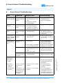
1
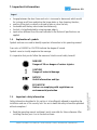
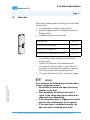
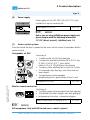
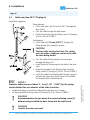
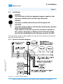
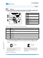
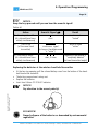
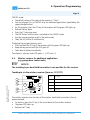
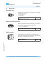
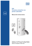
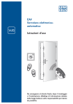
Winkhaus STV Operating Manual Electronic Automatic Locking System After installation please pass on these instructions to the end customer according to the Information Disclosure Act stipulated in the Law on Product Liability! Winkhaus STV Page 2 This security door locking system complies with the requirements and directives established and stipulated by the Council on the Harmonization of Legal Regulations of Member States regarding Electromagnetic Compatibility (89/336/EEC). The manufacturer shall hereby certify the conformity of this product and document such by the CE marking (see Appendix). Winkhaus STV GmbH & Co. KG Berkeser Straße 6 D-98617 Meiningen Germany Tel.:+49(0)36 93/9 50-0 Fax:+49(0)36 93/9 50-1 34 www.winkhaus.de The following information and graphic images provided correspond to the current status of the development and manufacture of this product. For the purpose of customer satisfaction and operational reliability of the electronic automatic locking system, we reserve the right to make changes to this product. Due to the nature of technical advances made, amendments to legal regulations and other compulsory changes we do not warrant for the correctness and completeness of the contents’ statements. We always do appreciate suggestions or comments. The electronic automatic locking system can be easily installed, if these operating instructions and the door specifications indicated have been followed. © Winkhaus STV GmbH & Co. KG. All rights reserved. Last revised: Mai/2005 Winkhaus STV GmbH & Co. KG · Berkeser Str. 6 · D-98617 Meiningen · Germany · www.winkhaus.de · [email protected] Operating Manual EAV 0124653 0505 Subject to technical changes All information and specifications given in this operating manual have been compiled and reviewed with utmost care. Table of Contents Winkhaus STV Page 3 Operating Manual EAV 0124653 0505 Subject to technical changes Table of Contents 1 1.1. 1.2. 1.3. 1.4. 1.5. 1.6. 2 3 3.1. 3.2. 3.3. 3.3.1. 3.4. 3.5. 3.5.1. 3.5.2. 4 4.1. 4.1.1. 4.2. 4.2.1. 4.2.2. 4.3. 4.3.1. 4.3.2. 4.4. 5 6 7 7.1. 7.2. 7.3. 8 Important information General information Intended use Use contrary to the intended purpose Explanation of symbols Important safety information Abbreviations/Explanations Product description Installation Cutting diagrams Cable transition KÜ-T STV (plug-in) Installations General connection diagram Access control system, transponder set Access control system, wireless remote control Wireless remote control set Wireless receiver (separate) Operation/Programming Electronic automatic locking system Locking and unlocking Electronic automatic door locking system with transponder Operation Programming Electronic automatic locking system with wireless remote control Operation Programming Wireless receiver for additional applications Maintenance and care Errors/Causes/Troubleshooting Technical specifications Antenna/Reader Unit Wireless remote control Cable transition Accessories Winkhaus STV GmbH & Co. KG · Berkeser Str. 6 · D-98617 Meiningen · Germany · www.winkhaus.de · [email protected] 4 4 4 5 6 6 7 8 14 14 16 17 17 18 20 20 22 24 24 24 24 24 25 27 27 27 31 33 34 35 35 35 36 37 1. Important information Winkhaus STV Page 4 1 Important information 1.1. General information Dear Customer, We would like to thank you for your confidence you have put in us by purchasing our high-quality product. Please read this operating manual carefully to become acquainted with the installation and use of this security door locking system and to avoid malfunctions and safety hazards. Acceptance class A 1.2. Intended use The complete door fittings are designed to be used in conjunction with the genuine Winkhaus parts. Other parts which are not recommended by Winkhaus can adversely affect the default properties of this locking system. We shall assume you use the lock as intended. The proper functions of the access control systems and of the accessory equipment included in the scope of delivery of the Winkhaus company have been tested. If you use components made by other companies and if you have any doubts about the suitability of these components, you will have to contact the respective manufacturer about their fitness for use. To ensure the intended use: • the information and instructions required for this purpose have to be passed on to the respective persons; • only trained professionals install the door fittings, locking units and accessory parts according to the installation instructions. DIN standards, which may also apply are to be followed, too. Winkhaus STV GmbH & Co. KG · Berkeser Str. 6 · D-98617 Meiningen · Germany · www.winkhaus.de · [email protected] Operating Manual EAV 0124653 0505 Subject to technical changes The electronic automatic locking system and the Winkhaus components recommended are suited for the following areas of application: • relative air humidity of max. 95% • ambient air temperature of between -20°C and +60°C. Winkhaus STV 1. Important information Page 5 The stipulations of use as intended have been met, once the Winkhaus fittings are: • installed according to their defined function and the installation specifications, • not used in another way than described, • maintained and cared for at regular intervals as instructed, • not used any longer if signs of wear are detected, • repaired by trained professionals in the event of malfunctions. The supplier/manufacturer does not accept any liability for personal injury or material damage caused by incorrect operation or improper use. 1.3. Use contrary to the intended purpose The locking systems are not designed to absorb or compensate for changes in shape or changes in the closing mechanism of the door caused by changes in temperature or in the structure of the building. Operating Manual EAV 0124653 0505 Subject to technical changes Doors which are used in damp rooms and in environments with aggressive corrosionpromoting air compositions require special door furniture. The locking systems are incorrectly used – that is use contrary to the one described above – is evident in particular, if: • the instructions on the intended use are not being followed; • the problem-free operation is hindered due to the installation of external objects and/or objects that are not purpose-conform in the opening zone, the locking system or within the center strike; • the locking system or the center strike is manipulated in such a way that its design, mode of operation or function is changed; • the door is drilled through in the area of the locking houses or of the lock rod once the lock has been installed; • the additional opening and closing members or the moved-out dead bolt are improperly used in order to keep the door open; • force is used to drive the handle pin through the lock spindle; • the locking elements are wrongly installed or are tampered with, e.g. by overpainting movable parts like the lock dead bolt or latch; • the locking system is subject to loads which exceed normal manual power and are transmitted via the cylinder key; • the handle is not loaded in the normal sense of rotation or a power above 150 N is applied onto the handle into the direction of actuation; Winkhaus STV GmbH & Co. KG · Berkeser Str. 6 · D-98617 Meiningen · Germany · www.winkhaus.de · [email protected] 1. Important information Winkhaus STV Page 6 • the gap between the door frame and sash is increased or decreased, which would for instance result from readjusting the hinge plates or from lowering the door; • auxiliary lifting tools or objects are used to open or close the lock; • the handle and the key are actuated simultaneously; • the lock is locked/unlocked by using improper objects; • input values different from the ones indicated in the Technical Specifications are applied. 1.4. Explanation of symbols Symbols and cues are used to identify important information in this operating manual. Cues such as DANGER or CAUTION indicate the degree of hazard. Symbols serve to visually emphasize the message. It is imperative that you do follow the measures listed to avoid safety hazards! DANGER! Danger of life or danger of serious injuries. CAUTION! Danger of material damage. NOTICE! Useful information and tips. 1.5. Important safety information Safety information described in this section is to be diligently adhered to regarding the installation and use of this security lock. You are to heed the safety information provided without exceptions! • Read the operating manual and keep it easily accessible for future reference. After installing the door pass it on to the end customer. Winkhaus STV GmbH & Co. KG · Berkeser Str. 6 · D-98617 Meiningen · Germany · www.winkhaus.de · [email protected] Operating Manual EAV 0124653 0505 Subject to technical changes ECO-WATCH! Notices on complying with regulations on environmental protection. Winkhaus STV 1. Important information Page 7 • The manufacturer shall not be held liable for damage caused by use contrary to the intended purpose of the product. • For security reasons, the lock has been designed to be used in conjunction with genuine Winkhaus parts. Using other parts may adversely affect the given properties of the security lock. • It must be ensured that the door can be closed without any problems by the key. • Installation/Repair of electrical equipment requires expertise, thus such work should only be carried out by an electrician. • Arbitrary modifications, changes or makeshift repairs are not permitted due to concerns for safety. You must only use genuine Winkhaus parts for replacements. • The manufacturer shall only be held liable for security related properties of the locking system as stipulated within the bounds of statutory regulations, if the manufacturer himself or another instructed, authorized agent has carried out the maintenance and service work or made the changes. • Winkhaus STV shall not be liable for any type of damage caused by inadequate repair or changes made. 1.6. Abbreviations/Explanations The following terms and abbreviations are used in this manual: STV AV2 EAV Operating Manual EAV 0124653 0505 Subject to technical changes Handle Grt. SB FRA M2 RS LS mc est gr Reader Security lock Automatic locking system Electronic automatic locking system Door handle Set Center strike – latch/bolt/ leveling member with 2 massive hooks DIN-right-handed DIN-left-handed Surface mat chrome-plated stainless steel gray pulverized Reader unit/control unit of the transponder set AC DC NO NC NO-NC ANT/GND UP-socket LED Alternating current Direct current Make contact Break contact Changer contact Auxiliary antenna/Ground Flush-type box Light emitting diode Winkhaus STV GmbH & Co. KG · Berkeser Str. 6 · D-98617 Meiningen · Germany · www.winkhaus.de · [email protected] 2. Product description Winkhaus STV Page 8 2 Product description The electronic automatic locking system is a state-of-the-art locking unit for securing and locking entry doors in a contact-free manner. Easy-to-use and convenient: All opening and closing members of the locking mechanism are power-driven. Operating Manual EAV 0124653 0505 Subject to technical changes In the external zone around the entry door Figure 2-1: Electronic automatic locking system with accessories Winkhaus STV GmbH & Co. KG · Berkeser Str. 6 · D-98617 Meiningen · Germany · www.winkhaus.de · [email protected] 2. Product description Winkhaus STV Operating Manual EAV 0124653 0505 Subject to technical changes Page 9 Included in standard delivery of the security lock MUST! be used* X X Available as accessory or as an option Supplied by customer/ not included in standard delivery No. Name [1] Automatic locking AV2 (AV2-F/U ...) [2] Motor box X X [3] Extension keep set/single strike X X [4] Center strike FRA ... X X [5] Cable transition (KÜ-T STV) X X [5.1] Cable at the sash side 2 m [2.187 yd] or 2.5 m [2.734 yd] long, plug for motor box included [5.2] Cable at the frame side 4 m [4.374 yd] long [6] Power supply 12 V DC/1 A X [7] Access control system (shown: antenna of the transponder set) NOTICE! Only install the antenna of the transponder set in the external zone around the entry door! X [8] “Open” key X [9] Flush-type box X [10] Handle X * remaining components recommended for use, or should be used alternatively Winkhaus STV GmbH & Co. KG · Berkeser Str. 6 · D-98617 Meiningen · Germany · www.winkhaus.de · [email protected] 2. Product description Winkhaus STV Page 10 Automatic locking system AV2 Automatic three-point locking system with protection unit against faulty switching, DIN RS and LS directions power-driven unlocking system (electric latch release) optionally available AV2-F 1660/35 92/8 M2 rs/ls mc AV2-F 1660/35 92/8 M2 rs/ls est AV2-F 1660/40 92/8 M2 rs/ls mc AV2-F 1660/40 92/8 M2 rs/ls est AV2-F 1660/40 92/10 M2 rs/ls mc AV2-F 1660/45 92/8 M2 rs/ls mc AV2-F 1660/45 92/8 M2 rs/ls gr AV2-F 1660/45 92/10 M2 rs/ls mc AV2-F 1660/50 92/8 M2 rs/ls mc AV2-F 1660/50 92/8 M2 rs/ls est AV2-F 1660/55 92/8 M2 rs/ls mc AV2-F 1660/55 92/10 M2 rs/ls mc AV2-F 1660/60 92/8 M2 rs/ls est AV2-F 1660/65 92/8 M2 rs/ls mc AV2-F 1660/65 92/8 M2 rs/ls est AV2-F 1660/65 92/10 M2 rs/ls mc AV2-F 2060/40 92/8 M2 rs/ls mc AV2-F 2060/45 92/8 M2 rs/ls mc AV2-F 2060/45 92/10 M2 rs/ls mc AV2-F 2060/55 92/8 M2 rs/ls mc AV2-F 2060/55 92/8 M2 rs/ls gr AV2-F 2060/55 92/10 M2 rs/ls mc AV2-F 2060/60 92/10 M2 rs/ls mc AV2-F 2060/65 92/8 M2 rs/ls mc AV2-F 2060/65 92/10 M2 rs/ls mc AV2-F 2460/35 92/8 M2 rs/ls mc AV2-F 2460/40 92/8 M2 rs/ls mc AV2-F 2460/40 92/8 M2 rs/ls gr AV2-F 2460/45 92/8 M2 rs/ls mc AV2-F 2460/45 92/10 M2 rs/ls mc AV2-U 2293/35 92/8 M2 rs/ls mc AV2-U 2293/45 92/8 M2 rs/ls gr AV2-U 2460/35 92/8 M2 rs/ls mc AV2-U 2460/40 92/8 M2 rs/ls mc AV2-U 2460/45 92/8 M2 rs/ls mc AV2-U 2460/45 92/8 M2 rs/ls gr AV2-U 2460/45 92/10 M2 rs/ls mc AV2-U 2471/35 92/8 M2 rs/ls mc AV2-U 2471/35 92/8 M2 rs/ls gr AV2-U 2471/35 92/8 M2 rs/ls est AV2-U 2471/45 92/8 M2 rs/ls mc AV2-U 2471/45 92/8 M2 rs/ls gr 123 536 3/123 537 2 124 212 2/124 213 1 123 540 7/123 541 6 124 214 0/124 215 9 123 542 5/123 543 4 123 544 3/123 545 2 124 060 5/124 061 4 123 546 1/123 547 0 124 312 1/124 313 0 124 216 8/124 217 7 123 548 9/123 549 8 123 854 7/123 855 6 124 218 6/124 219 5 123 791 3/123 792 2 124 220 2/124 221 1 123 550 4/123 551 3 123 552 2/123 553 1 123 554 0/123 555 9 123 556 8/123 557 7 123 558 6/123 559 5 124 074 9/124 075 8 123 891 2/123 892 1 123 560 2/123 561 1 123 562 0/123 563 9 123 564 8/123 565 7 123 566 6/123 567 5 123 568 4/123 569 3 123 895 8/123 896 7 123 694 1/123 695 0 123 777 1/123 778 0 123 755 7/123 756 6 123 713 8/123 714 7 123 570 0/123 571 9 123 596 0/123 597 9 123 574 6/123 575 5 123 779 9/123 780 6 123 572 8/123 573 7 123 538 1/123 539 0 123 863 6/123 864 5 124 291 6/124 292 5 123 684 3/123 685 2 124 026 8/124 027 7 Winkhaus STV GmbH & Co. KG · Berkeser Str. 6 · D-98617 Meiningen · Germany · www.winkhaus.de · [email protected] Operating Manual EAV 0124653 0505 Subject to technical changes [1] 2. Product description Winkhaus STV Page 11 [2] Motor box Motor box for power-driven unlocking, control included, without cable • for transponder or wireless remote control • optional: triggering unit for swing door opener via floating contact • available mounted or not mounted Motor box EAV 1) 123 770 8 G2 motor box EAV mounted 2) 123 771 7 Motor box EAV (swing door) 3) 123 772 6 G2 motor box EAV (swing door) mounted 2) 3) 123 773 5 1) 2) 3) for retrofitting simply screwing to the automatic locking system Caution: Pay attention to left-handed thread! if an automatic locking system + motor box EAV, mounted, are simultaneously ordered supply of the locking system with mounted motor box incl. signal (floating contact) for swing door opener. Operating Manual EAV 0124653 0505 Subject to technical changes NOTICE! Please observe the following instructions when using a swing door opener: • Ensure that the motor can open the closing member at any time. • After unlocking, the control unit sends a signal to the swing door opener which must swivel out then immediately. • If the swing door drive is triggered at another point of time, malfunctions can be caused. • If the main hook is unlocked manually, the door may not be actuated electrically. Winkhaus STV GmbH & Co. KG · Berkeser Str. 6 · D-98617 Meiningen · Germany · www.winkhaus.de · [email protected] 2. Product description Winkhaus STV Page 12 [3] Extension keep set/single strikes Select the corresponding standard frame parts in the current program manual (single strikes/alternatively extension keep set): Program Manual Wood/Plastic/ALU 0804 012 405 6 Program Overview STV-System Wood Group 2 Program Overview STV-System Plastics Group 2 Program Overview STV-System Aluminum Group 2 (Example: profile Thyssen; frame L30; sash H40 extension keep set U26-192) When ordering always indicate the DIN direction RS or LS. [4] Center strike FRA Center keep for latch and dead bolt of plastics, aluminum and wooden entryway doors. [5] Cable transition KÜ-T STV Plug-in and concealed cable transition • plugable by plug-in function with retaining screws • sash element with spring jacket and cable of 2 m [2.187 yd] or 2.5 m [2.734 yd] (plug for motor box included) • frame element with cable of 4 m [4.374 yd] • concealed in the airgap • used as the electric interface (max. 24 V DC/2 A) between the sash of the door and the frame • color: silver/gray • it must not be cut-out for notch air from 11 mm [0.433“], suited for entry doors of plastics or aluminum (depends on the system) Cable transition KÜ-T STV 123 399 9 Cable transition KÜ-T-STV-FL 2.5 m 123 336 3 Winkhaus STV GmbH & Co. KG · Berkeser Str. 6 · D-98617 Meiningen · Germany · www.winkhaus.de · [email protected] Operating Manual EAV 0124653 0505 Subject to technical changes Select the respective keeps also according to the profile systems in the current program manual (see above). 2. Product description Winkhaus STV Page 13 [6] Power supply Power supply unit for EAV: 230 V, 50 Hz/12 V DC, to be installed on a top hat mounting rail Power supply 12 V DC/1 A 124 017 9 NOTICE! Unless you are using a Winkhaus power supply unit, please keep in mind the following information: 12 V DC (direct current), stabilized, min. 1 A [7] Access control systems From the outside the door is opened via the access control system (transponder, wireless remote control). Transponder set EAV Consisting of: • 1 reader/control unit (for flush-type box) • 1 antenna for exposed installation (90 x 90 x 13 mm, [3.543 x 3.543 x 0.512 “], color: white), cable of 2.5 m [2.734 yd] fixed at the antenna • 1 antenna sticker, weatherproof, resistant to UV light • 3 transponder chips (key tags, color: blue, have not been taught) • 2 programming card transponders (programming card = green; delete-all card = red) Operating Manual EAV 0124653 0505 Subject to technical changes Transponder set T02 EAV 123 774 4 Wireless remote control set Consisting of: • 1 wireless receiver (to be inserted in the flush-type box) • 3 hand-held transmitters (taught, color: dark gray/gray) • programming instruction + connection diagram Wireless remote control F02, dark gray, set 3 + 1 123 775 3 NOTICE! VdS acceptance: Only with VdS-tested access control systems! Winkhaus STV GmbH & Co. KG · Berkeser Str. 6 · D-98617 Meiningen · Germany · www.winkhaus.de · [email protected] 3. Installation Winkhaus STV Page 14 3 Installation 3.1. Cutting diagrams NOTICE! Important for wooden entry doors: Please enlarge the cut-out for the additional locking houses up to 47 mm [1.850“]! Figure 3.1-1: Dimensions for the electronic automatic locking system Winkhaus STV GmbH & Co. KG · Berkeser Str. 6 · D-98617 Meiningen · Germany · www.winkhaus.de · [email protected] Operating Manual EAV 0124653 0505 Subject to technical changes For installing the electronic automatic locking system it is required to cut out a standard three-point locking system and additionally the motor box, as shown in the following figures. Winkhaus STV 3. Installation Page 15 Figure 3.1-2: Situation of the motor box for the electronic automatic locking system Operating Manual EAV 0124653 0505 Subject to technical changes Figure 3.1-3: Situation of the main locking house for the electronic automatic locking system NOTICE! a) The cut-out for the main locking house must be 16 mm [0.630“] as minimum to provide the free motion of the drive rod! Check the door fitting groove for cleanness so that the free motion of the rod is not limited! b) It is recommended to use it always with a so called alternate furniture set (latch inside, knob outside). Winkhaus STV GmbH & Co. KG · Berkeser Str. 6 · D-98617 Meiningen · Germany · www.winkhaus.de · [email protected] 3. Installation Winkhaus STV Page 16 3.2. Cable transition KÜ-T STV (plug-in) Installation sequence: Frame element: • Drill a hole with a of 6 mm [0.236“] through the door frame. • Pass the cable through the door frame. • Fasten the element with the fitting screw [1] having a of 4 x 25 mm [0.984“]. Sash element • Drill a hole of 13 mm [0.512“] through the fitting groove up to the glass groove. CAUTION! The bore hole must be burr-free. The spring must be under a slight pre-tension even with the door being closed. NOTICE! Provide a cable reserve of about 3 - 5 cm [1.181 - 1.969“] for the spring tension behind the sash element of the cable transition. • Establish the plug-in connection after putting the door on its hinges. • Fix the plug with the fitting screw [3] having a of 4 x 25 mm [0.984“]. CAUTION! Recommendation: Do not mount the second retaining screw [3] before having installed the door frame into the wall reveal. CAUTION! Insulate the wires not used! Winkhaus STV GmbH & Co. KG · Berkeser Str. 6 · D-98617 Meiningen · Germany · www.winkhaus.de · [email protected] Operating Manual EAV 0124653 0505 Subject to technical changes • Pass the cable with the plug for the motor box through the door sash. • Insert the end of the spring into the hole in the door sash. • Fasten the element in the fitting nut by using the fitting screws [2] having a of 4 x 25 mm [0.984“]. • Install the cable for example within the glass groove towards the motor box; install the rest of the cable for example within the hollow cell. Winkhaus STV 3. Installation Page 17 3.3. Installations DANGER! The installation of electrical equipment requires expertise, thus such work should only be carried out by electricians. DANGER! Generally, assemble and install only with the power off! CAUTION! It must be easily possible to lock the door mechanically, only then check the electric function! If you connect an intercom system take care that the button of this system is designed as a floating contact! External voltage must not be transmitted from the intercom system to the lock! Operating Manual EAV 0124653 0505 Subject to technical changes If the operating voltage has been applied (start-up), the motor brings the closing members into the neutral position. 3.3.1. General connection diagram Figure 3.3.1-1: General connection diagram Winkhaus STV GmbH & Co. KG · Berkeser Str. 6 · D-98617 Meiningen · Germany · www.winkhaus.de · [email protected] 3. Installation Winkhaus STV Page 18 3.4. Access control system, transponder set Prerequisites for installation: • The transponder signal is processed in the reader/control unit. • This unit has to be installed in a standard flush-type box inside the building (close to the door). NOTICE! Should you want to accommodate the control unit and button in the same flush-type box, this one must have a depth of 65 mm [2.559“]. • Unless you use a button beside the door, you will have to install a flush-type box with a filler panel for the reader unit. DANGER! For safety reasons, you are not permitted to install it in a flush-type box with a 230 V switch or socket outlet! • The transponder antenna is located in a housing in exposed installation and is to be installed in a weatherproof zone outside the entry door. • Do not mount the antenna directly on metal as its range could be decreased drastically. • Do not mount any other antenna within a radius of 1 m [1.094 yd]! NOTICE: If you plan installations on a metal substructure, you will have to use a wooden board and spacer bolts, if applicable, or large bore holes to ensure the proper function of the antenna! To test the scanning performance, you may have to tentatively install it on site, if applicable! • Connect the cable of the antenna to the reader/control unit. • We recommend: Lay a reserve pipe from the antenna to the reader unit. Winkhaus STV GmbH & Co. KG · Berkeser Str. 6 · D-98617 Meiningen · Germany · www.winkhaus.de · [email protected] Operating Manual EAV 0124653 0505 Subject to technical changes 3. Installation Winkhaus STV Page 19 No. Terminals 1 12 V DC 2 0 V DC 3 serial interface 4 serial interface 5 antenna 6 antenna 7 floating contact C 8 floating contact NO Operating Manual EAV 0124653 0505 Subject to technical changes Figure 3.4-1: Terminal assignment of the transponder reader Figure 3.4-2: Installation of the transponder reader Winkhaus STV GmbH & Co. KG · Berkeser Str. 6 · D-98617 Meiningen · Germany · www.winkhaus.de · [email protected] 3. Installation Winkhaus STV Page 20 3.5. Access control system, wireless remote control Prerequisites for installation: • To ensure the reliable performance, the position of the wireless receiver is of utmost importance for the received power. • Do not install it at or nearby sources of possible interference (e.g. EDP/high-performance power distributor) • To prevent manipulations to the receiver we recommend installing the receiver on the inner side of the door! 3.5.1. Wireless remote control set Installation sequence: • Install the wireless receiver in a standard flush-type box on the inside. NOTICE! If you use the flush-type box of the button, the box will have to be 65 mm [2.559“] deep! • Unless you use a switch or button beside the door; you will have to provide a flushtype box with a filler panel for the wireless receiver. DANGER! For safety reasons, you are not permitted to install it in a flush-type box with a 230 V switch or socket outlet! • Connect the terminals 2 through 5 of the wireless receiver as described in the table below. Terminals 1 “Break contact (NC)”, is not required 2 connect “Contact (C)” - to the green wire at the cable transition 3 connect “Make contact (NO)” - to terminal 4 of the wireless receiver (+ 12V DC) 4 connect “12 V DC or 24 V DC” - with the white wire of the cable transition + terminal 2 of the wireless receiver 5 Connect “0 V DC” - with the brown wire of the cable transition 6 “Auxiliary antenna/ANT” (not required) 7 “Auxiliary antenna/GND” (not required Figure 3.5.1-1: Terminal assignment of the wireless receiver Winkhaus STV GmbH & Co. KG · Berkeser Str. 6 · D-98617 Meiningen · Germany · www.winkhaus.de · [email protected] Operating Manual EAV 0124653 0505 Subject to technical changes No. Winkhaus STV 3. Installation Page 21 Name [8] “P1 key” [9] “green LED” [10] “red LED” [11] “buzzer” [12] “relay” [13] “jumper” 12 V/ 24 V Operating Manual EAV 0124653 0505 Subject to technical changes No. Figure 3.5.1-2: Installing the wireless receiver Winkhaus STV GmbH & Co. KG · Berkeser Str. 6 · D-98617 Meiningen · Germany · www.winkhaus.de · [email protected] 3. Installation Winkhaus STV Page 22 12 V = delivery status 24 V Figure 3.5.1-3: Adjustment of the jumper for voltage selection • The default setting of the jumper is 12 V. • The wireless receiver can be adjusted from 12 V to 24 V via the jumper. NOTICE! Check the proper position of the jumper before starting operation! Figure 3.5.2-1: Installing the wireless receiver Installation sequence: • Remove the cover of the housing. • Fasten the housing with screws. • Push in the rubber plug (see Figure 3.5.2-1). • Insert the circuit board of the receiver according to figure 3.5.2-2 and connect it to the control of the additional application (for example to the garage door control unit). Winkhaus STV GmbH & Co. KG · Berkeser Str. 6 · D-98617 Meiningen · Germany · www.winkhaus.de · [email protected] Operating Manual EAV 0124653 0505 Subject to technical changes 3.5.2. Wireless receiver (separate) Separate wireless receiver for additional applications, such as garage door control units. 3. Installation Winkhaus STV Page 23 NOTICE! Do follow the relevant installation instructions of the additional applications! • Put the cover back on the housing and lock and screw it down. No. Terminals 8, 9 NO relay K4 - non-operated contact is open, it closes by activating per hand-held transmitter 9, 10 NC relay K4 - non-operated contact is close, it opens by activating per hand-held transmitter 11, 12 “12 V AC/DC” 11, 13 “24 V AC/DC” 14 “Antenna” 15 “Screen” Operating Manual EAV 0124653 0505 Subject to technical changes Figure 3.5.2.-2: Terminal assignment of the circuit board of the receiver No. Name [1] “JP1 jumper” [2] “P1 key” [3] “K4 relay” [4] “red LED” [5] “green LED” • You can set the K4 relay as ON/OFF or as an impulse via the JP1 jumper (see figure 3.5.2-3). The setting depends on the control unit which is to be triggered by the receiver. JP1 = ON K4 ON/OFF • Relay remains active after being activated per hand-held transmitter. • Deactivation by actuating the hand-held transmitter once more. JP1 = OFF K4 Impuls • Relay becomes briefly active after being activated per hand-held transmitter and after about 1 sec. it will be deactivated automatically. Figure 3.5.2-3: Setting the K4 relay Winkhaus STV GmbH & Co. KG · Berkeser Str. 6 · D-98617 Meiningen · Germany · www.winkhaus.de · [email protected] 4. Operation/Programming Winkhaus STV Page 24 4 Operation/Programming 4.1. Electronic automatic locking system 4.1.1. Locking and unlocking Locking: • Even when closing the door it is automatically locked by two massive hooks and the latch in the main locking house. • Additional protection is provided by manual locking: one rotation of the key (1 x 360°) causes the dead bolt in the main locking house to be moved out. Opening the door from outside: • Unlocking via the connected access control system (e.g. transponder, wireless remote control) or with a key. NOTICE! The main dead bolt for additional protection must be unlocked by keys in any case. Opening the door from inside, e.g. via: • the button • the intercom (floating contact button!) • the handle or key* * even possible in case of power failure Electronic automatic door locking system with transponder 4.2.1. Operation The reader unit controls and monitors the access to the door. • It is operated by means of transponders that work contactless. • Hold a tutored transponder chip into the proximity (0 - 8 cm, [0 - 3.150“]) of the antenna. • Once the transponder chip is close enough to where it can read the information, communication is established contactfree. • The transponder data are transmitted to the reader unit via the antenna. • An acoustic signal at the reader unit will acknowledge the data transfer. • The reader checks whether this transponder chip is authorized to access and okays or denies access. Winkhaus STV GmbH & Co. KG · Berkeser Str. 6 · D-98617 Meiningen · Germany · www.winkhaus.de · [email protected] Operating Manual EAV 0124653 0505 Subject to technical changes 4.2. 4. Operation/Programming Winkhaus STV Page 25 Action Door with transponder “Open” Acoustic Signal short, short Result authorized • After the enable time has elapsed, another transponder can be recognized and evaluated anew. • If a transponder chip is unknown to the reader, it does not have access rights and access will be denied. Action Door with transponder “Open” Acoustic Signal short, long Result not authorized 4.2.2. Programming Each transponder set is supplied with 2 programming card transponders. (programming card = green; delete-all card = red) These cards are taught at this reader/control unit. Teach-in mode • Programming card: Set teach-in mode Teach transponder Operating Manual EAV 0124653 0505 Subject to technical changes ProgrammierKarte Action Pass the programmable card over the antenna Acoustic Signal short, every 0.5 seconds Result teach-in mode “active” • If you do not swipe the transponder chip across the antenna for a period of 5 seconds, the teach-in mode will be stopped. The reader unit returns to operating mode. Winkhaus STV GmbH & Co. KG · Berkeser Str. 6 · D-98617 Meiningen · Germany · www.winkhaus.de · [email protected] 4. Operation/Programming Winkhaus STV Page 26 Action Pass all the transponders to be tutored in succession over the antenna Action Acoustic Signal for about 1 second Acoustic Signal Result transponders “tutored” Result Pass all the transponders no acoustic signal memory over to be tutored in succession (no more transponders can (250 transponders have over the antenna be tutored) already been programmed) Delete mode • Delete-all card: Delete mode “All transponders“ Deletes all transponders (key tags) CAUTION! By using the delete-all card all the transponders stored in the system will be deleted! The action of deleting all transponders is irrevocable once the process has been completed! You have to teach up to 250 new transponders from the start! The programming cards cannot open the door! Action Pass the delete-all card over the antenna Acoustic Signal for about 1 second Result end of delete mode “All transponders” Winkhaus STV GmbH & Co. KG · Berkeser Str. 6 · D-98617 Meiningen · Germany · www.winkhaus.de · [email protected] Operating Manual EAV 0124653 0505 Subject to technical changes Gesamt Lösch-Karte 4. Operation/Programming Winkhaus STV Page 27 NOTICE! All transponders have been deleted and the reader unit is at delivery status. The delete-all card and the programming card are saved, a transponder is not saved. In this state you cannot open the door via transponder or card; rather you will have to teach-in the transponder anew. NOTICE! Keep the programming cards at a safe place to prevent any kind of misuse. If you lose the cards, the reader unit will have to be exchanged in its entirety! Please contact customer service in such a case. 4.3. Electronic automatic locking system with wireless remote control 4.3.1. Operation • It is operated via the wireless hand-held transmitters working contactless. • The set of 3 wireless hand-held transmitters delivered have already been taught (key A). • To trigger a signal, press the A key of a taught-in hand-held transmitter. The red LED will turn on and the door will be unlocked. Operating Manual EAV 0124653 0505 Subject to technical changes 4.3.2. Programming You can program the wireless remote control via the wireless hand-held transmitter or the wireless receiver. We recommend programming it by using the wireless hand-held transmitter. The programming per hand-held transmitter is not possible for the wireless receiver for additional applications. Teaching a wireless hand-held transmitter directly at the hand-held transmitter (recommended) red LED key A key B Winkhaus STV GmbH & Co. KG · Berkeser Str. 6 · D-98617 Meiningen · Germany · www.winkhaus.de · [email protected] 4. Operation/Programming Winkhaus STV Page 28 NOTICE! Keep the keys pressed until you hear the acoustic signal at the receiver! Action 1) Press keys A and B (of a tutored hand transmitter) simultaneously* 2) Press A key (of the same hand transmitter) 3) Press all keys to be taught in succession, as long as the Teach-in mode is “active” Acoustic Signal short continuous signal (as long as Teach-in mode is “active”) continuous signal is briefly interrupted Result teach-in mode “started” teach-in mode “active” (pressed) key(s) is/are taught-in * If no hand-held transmitter has been taught (for example after “delete-all” function), it would apply to all hand-held transmitters. The teach-in mode can be started with any hand-held transmitter. Deleting wireless hand-held transmitters directly via the hand-held transmitter Partial deletion: 1) Press keys A and B (of a tutored hand transmitter) simultaneously* 2) Press A key (of the same hand transmitter) Acoustic Signal brief continuous signal (as long as delete mode is “active”) 3) Press all the keys to be deleted in succession, as continuous signal is briefly long as the delete mode is interrupted “active” Result teach-in mode “started” teach-in mode “active” (pressed) key(s) is/are “deleted” Winkhaus STV GmbH & Co. KG · Berkeser Str. 6 · D-98617 Meiningen · Germany · www.winkhaus.de · [email protected] Operating Manual EAV 0124653 0505 Subject to technical changes Action 4. Operation/Programming Winkhaus STV Page 29 NOTICE: Keep the keys pressed until you can hear the acoustic signal! Delete-all: Action 1) Press keys A and B (of a tutored hand transmitter) simultaneously 2) Press A key (of the same hand transmitter) 3) Press keys A and B (of a tutored hand transmitter) simultaneously Acoustic Signal short continuous signal (as long as the delete mode is “active”) short, 3 times Result teach-in mode “started” teach-in mode “active” memory of the receiver is “completely deleted” (no hand transmitter taught) Replacing the batteries at the wireless hand-held transmitter • At the key ring opening, pull the colored battery cover from the bottom of the handheld transmitter outwards. • The battery compartment swings out. • Replace the batteries. • Insert two Lithium CR 2016.31 batteries. Operating Manual EAV 0124653 0505 Subject to technical changes NOTICE! Pay attention to the correct polarity! ECO-WATCH! Properly dispose of the batteries as demanded by environmental regulation! Winkhaus STV GmbH & Co. KG · Berkeser Str. 6 · D-98617 Meiningen · Germany · www.winkhaus.de · [email protected] 4. Operation/Programming Winkhaus STV Page 30 Teaching wireless hand-held transmitters directly via the receiver [8] „P1 key” [9] „green LED” [10] „red LED” [11] „buzzer” [12] „relay” [13] „jumper” • If the programming is performed via the receiver, this one will have to be freely accessible. • Press the P1 key of the receiver until the green LED lights up. • Release the key. • Activate the desired key of the hand-held transmitter while the LED is lit up • As long as the LED is lit, you can program additional hand-held transmitter keys. Display Memory full: The memory has been filled to capacity (max. 85 keys), if the teach-in key of a new wireless hand-held transmitter is used and both LED displays of the receiver flash simultaneously. Partial deletion: • Press and hold the P1 key of the receiver until the green LED lights up. • Release the key. • Press the key of the wireless hand-held transmitter while the LED is lit up. • A taught-in wireless hand-held transmitter will be deleted automatically. • A wireless hand-held transmitter that has not been taught will be programmed (analogue ”Teaching-in of wireless hand-held transmitters directly via the hand-held transmitter”). Delete-all: • Press and hold the P1 key of the receiver until the green LED lights up. • Release the key. • Press the key again until the green and the red LED flash three times. • Now, all hand-held transmitters are deleted. Winkhaus STV GmbH & Co. KG · Berkeser Str. 6 · D-98617 Meiningen · Germany · www.winkhaus.de · [email protected] Operating Manual EAV 0124653 0505 Subject to technical changes Deleting wireless hand-held transmitters directly via the receiver Winkhaus STV 4. Operation/Programming Page 31 ON/OFF mode: • The default setting of the relay of the receiver is “Pulse”. • You can program it as an ON/OFF relay for additional applications (specified by the respective application). • For this purpose, press the P1 key of the receiver until the green LED lights up. • Release the key again. • Press the P1 key once more. • The LED flashes and the relay is switched to the ON/OFF mode. • Use the same procedure to get to the pulse mode. • Then, the LED will be lit continuously. Displaying the occupied memory units: • Press and hold the P1 key of the receiver until the green LED lights up. • Keep the key pressed until the LED goes off. • Then release the key immediately. The display is a binary code: LED green = 1, LED red = 0 4.4. Wireless receiver for additional applications (e.g. garage door control units) NOTICE! The teaching-in per hand-held transmitter is not possible for this receiver. Operating Manual EAV 0124653 0505 Subject to technical changes Teaching-in via the wireless receiver (item no.: 1231777) [1] „JP1 jumper“ [2] „P1 key” [3] „K4 relay ” [4] „red LED” [5] „green LED” The wireless receiver saves the keys of the wireless hand-held transmitter in the sequence entered. • To teach-in, press the P1 key of the circuit board of the wireless receiver. • The green LED lights up. • Release the P1 key. Winkhaus STV GmbH & Co. KG · Berkeser Str. 6 · D-98617 Meiningen · Germany · www.winkhaus.de · [email protected] 4. Operation/Programming Winkhaus STV Page 32 • Then, press the key of the wireless hand-held transmitter you would like to save. • The LED turns off. • The desired key of the wireless hand-held transmitter has been taught in. Deleting via the wireless receiver Partial deletion: • Press and hold the P1 key for about 2 seconds. • When the green LED lights up, release the P1 key. • Press the key of the wireless hand-held transmitter you would like to delete. • The deletion of the key is signalized by the flashing LED. Delete-all: • Press and hold the P1 key until the green LED lights up. • Release the P1 key. • When the LED lights, press the P1 key again until both LEDs flash three times. Operating Manual EAV 0124653 0505 Subject to technical changes The memory is full once 85 keys have been saved in the wireless hand-held transmitter. Now it is not possible to save additional wireless hand-held transmitters. This condition is indicated in the teach-in mode by both LED displays flashing simultaneously three times. Winkhaus STV GmbH & Co. KG · Berkeser Str. 6 · D-98617 Meiningen · Germany · www.winkhaus.de · [email protected] Winkhaus STV 5. Maintenance and care Page 33 5 Maintenance and care • Components of the door furniture relevant to security have to be checked for tightness and wear at regular intervals. If required, the retaining screws should be retightened and defective parts should be replaced. • Check the locking mechanism and smooth operation of the security lock at regular intervals (at least once every three months). • At least once a year - more frequently if under a higher stress factor - all moveable parts and all accessible sliding members of the locking system need to be lubricated with Vaseline and checked for proper performance regarding mechanics and electronics. • You should only use neutral cleaning agents or care products that do not contain any abrasives to protect the anticorrosion coat of the door furniture. Operating Manual EAV 0124653 0505 Subject to technical changes • Clean electronic parts only in a dry state. Winkhaus STV GmbH & Co. KG · Berkeser Str. 6 · D-98617 Meiningen · Germany · www.winkhaus.de · [email protected] 6. Errors/Causes/Troubleshooting Winkhaus STV Page 34 Errors/Causes/Troubleshooting Error Indication Possible cause Troubleshooting the door does not lock automatically hooked locking tongue possibly not locked • check the installation, if required the strikes • adjust the hinge plates the latch is “blocked” the door is not closed in the center range • the door is warped • the contact pressure is too high • the door has not been installed properly • the cut-out in the area of the main locking house is possibly not sufficient (dimensions see page 14) • the door sash has not been mounted properly the door cannot be the tracer is “bloclosed cked” at the single strike the motor does not function although voltage is applied at the door the door cannot be opened by the motor the door cannot be opened • no voltage supply via the cable transition the motor does not function • power failure • the motor stops • • • the motor functions • but the door cannot be opened • at the single strike change the height of the door striker (by using a screw driver) • check the cable transition (e. g. contacts, screwed joint for KÜ-T STV) • unlock mechanically via profile cylinder/handle or lock via profile cylinder power supply is interrupted, • check KÜ (correct the plugin e. g. at the cable transition connection) or see above the door is warped • adjust the door the contact pressure is too • check the soft movement high via profile cylinder/handle the lock is too tight the main bolt is unlocked • draw the main bolt back via profile cylinder again via the profile cylinder Power failure when/during: a) the door is locked b) the door is open, lock is unlocked c) the unlocking procedure • recut, if necessary the door is possibly • the motor is not in starting not held by the position latch when the door is lo- • the motor is not in starting cked again, possibly position the M-hook, main bolt do not lock completely • the door can be operated mechanically (profile cylinder/handle) • close the door by prelocking the main bolt, if necessary • door can be operated mechanically (profile cylinder/handle), if motor has returned to starting position completely functions Winkhaus STV GmbH & Co. KG · Berkeser Str. 6 · D-98617 Meiningen · Germany · www.winkhaus.de · [email protected] Operating Manual EAV 0124653 0505 Subject to technical changes 6 Winkhaus STV 7. Technical specifications Page 35 7 Technical specifications 7.1. Antenna/Reader Unit Dimensions (antenna): Dimensions (reader): Reading distance: Signalization: Data memory: Reader technique: Power consumption: Voltage: Operating Manual EAV 0124653 0505 Subject to technical changes 7.2. antenna housing: 90 x 90 x 13 mm [3.543 x 3.543 x 0.512“], for exposed installation, cable is permanently installed 45 x 45 x 22 mm [1.772 x 1.772 x 0.866“] between 0 and 8 cm [0 - 3.150“] (depending on the installation environment) piezo-buzzer max. 250 transponders Prox reader max. 100 mA 12 V AC/DC Wireless remote control Receiver type: Modulation: Frequency: Number of code combinations: Frequency of the local oscillator: Intermediate frequency: Sensitivity (to receive signals): Input impedance: Maximum memory capacity: Power supply: Closed-circuit current: On-load current: Number of relays: Dimensions (receiver): Range: Superheterodyne AM/ASK 433.92 MHz 2 to the power of 64 („Rolling Code“) 6.6128 MHz 10.7 MHz -115 dB 50 ohm max. 85 keys 12/24 V AC/DC 10 mA 23 mA 1 (NO-NC), output 24 V A 44 x 33 x 17 mm [1.732 x 1.299 x 0.669“] max. 30 meters [32.808 yd] (unobstructed area) 200 meters [218.72 yd] with antenna Wireless hand-held transmitter Number of operations: 2 channel Power supply: Lithium CR 2016.31 battery Service life of batteries: 18 - 24 months Winkhaus STV GmbH & Co. KG · Berkeser Str. 6 · D-98617 Meiningen · Germany · www.winkhaus.de · [email protected] 7. Technical specifications Winkhaus STV Page 36 Power consumption: Frequency: Number of code combinations: Modulation: Rated output E.R.P.: Range in an unobstructed area: Dimensions (wireless hand-held transmitter): Wireless receiver (separate) Receiver type: Modulation: Frequency: Frequency of the local oscillator: Intermediate frequency: Sensitivity (to receive signals): Input impedance: Maximum memory capacity: Power supply: Closed-circuit current: On-load current: Number of relays: Power: Dimensions: 61 x 36 x 16 mm [2.402 x 1.417 x 0.630“] Superheterodyne AM/ASK 433.92 MHz 6.6128 MHz 10.7 MHz 115 dB 50 Ohm 85 codes for hand-held transmitter 12/24 V AC/DC 15 mA 33/48 mA (1 NO-NC) 24 W 80 x 80 x 50 mm [3.150 x 3.150 x 1.969“] Cable transition Cable transition KÜ-T STV Measurements: Number of wires: Cross section of wires: Sash element: Frame element: Max. voltage: Max. switching current: total component length of about 222 mm [8.740“] 5 0.25 mm² with a cable of 2 m [2.187 yd] with a cable of 4 m [4.374 yd] 24 V DC 2 A per connection line Winkhaus STV GmbH & Co. KG · Berkeser Str. 6 · D-98617 Meiningen · Germany · www.winkhaus.de · [email protected] Operating Manual EAV 0124653 0505 Subject to technical changes 7.3. 13 mA 433.92 MHz 2 to the power of 64 (as “Rolling Code“) AM/ASK 50 - 100 µW max. 30 m [32.808 yd] 8. Accessories Winkhaus STV Page 37 8 Accessories Transponder chip Transponder chip (separate) as an extension to transponder set EAV (123 774 4). • form: key tag • color: blue Transponder chip T01 blue 123 131 2 Wireless hand-held transmitter Wireless hand-held transmitter (separate) as an extension to the wireless remote control set (123 775 3). • color: dark gray/gray Wireless hand-held transmitter F01 dark gray 123 133 0 Wireless receiver Wireless receiver (separate); e.g. for coupling with the garage door control unit (the second key at the hand-held transmitter can be used for this purpose) 123 177 7 Operating Manual EAV 0124653 0505 Subject to technical changes Wireless receiver F01 Winkhaus STV GmbH & Co. KG · Berkeser Str. 6 · D-98617 Meiningen · Germany · www.winkhaus.de · [email protected] Winkhaus STV PageDeclaration 38 EC of Conformity For the products: Electronic Automatic Locking System in the design: Safety door locking system AV2 + motor control EAV 1 (mounted/not mounted) we shall hereby certify that they conform to the requirements and directives established and stipulated by the Council on the Harmonization of Legal Regulations of Member States regarding Electromagnetic Compatibility (89/336/EEC). The following standards have been applied to assess the electromagnetic compatibility of the product: Emitted interference according to: EN 61000 - 6 - 3 Immunity to interference according to: EN 61000 - 6 - 2 This declaration is made on behalf of the manufacturer: and authorized by: Meiningen, 09 July 2004 ................................................................... p.p. Dr. Warnow Title: Technical Director Winkhaus STV GmbH & Co. KG · Berkeser Str. 6 · D-98617 Meiningen · Germany · www.winkhaus.de · [email protected] Operating Manual EAV 0124653 0505 Subject to technical changes Winkhaus STV GmbH & Co. KG Berkeser Str. 6 D-98617 Meiningen Germany Winkhaus STV Operating Manual EAV 0124653 0505 Subject to technical changes Page 39 Winkhaus STV GmbH & Co. KG · Berkeser Str. 6 · D-98617 Meiningen · Germany · www.winkhaus.de · [email protected] Winkhaus STV Operating Manual EAV 0124653 0505 Subject to technical changes Page 40 Winkhaus STV GmbH & Co. KG · Berkeser Str. 6 · D-98617 Meiningen · Germany · www.winkhaus.de · [email protected]