1
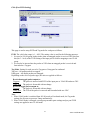
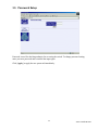
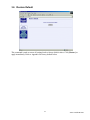
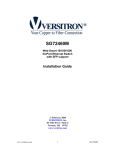
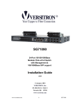
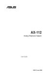
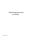
S7055xM
Web Smart Managed
5-Port 10/100 Fast Ethernet
Switch w/VLAN Support
Installation Guide
Copyright January 2005
VERSITRON, Inc.
83 Albe Drive / Suite C
Newark, DE 19702
www.versitron.com
A050130380
The information contained in this document is subject to change without prior notice.
Copyright © All Rights Reserved.
TRADEMARKS
Ethernet is a registered trademark of Xerox Corp.
This device complies with Class A Part 15 of the FCC Rules. Operation is subject to the following two
conditions: (1) this device may not cause harmful interference and (2) this device must accept any
interference received including the interference that may cause.
CISPR A COMPLIANCE
This device complies with EMC directive of the European Community and meets or exceeds the
following technical standard.
EN 55022 - Limits and Methods of Measurement of Radio Interference Characteristics of Information
Technology Equipment. This device complies with CISPR 22 Class A.
WARNING: This is a Class A product. In a domestic environment this product may cause radio
interference in which case the user may be required to take adequate measures.
CE NOTICE
Marking by the symbol
indicates compliance of this equipment to the EMC directive of the
European Community. Such marking is indicative that this equipment meets or exceeds the following
technical standards:
EN 55022: Limits and Methods of Measurement of Radio Interference characteristics of Information
Technology Equipment.
EN 50082/1: Generic Immunity Standard – Part 1: Domestic Commercial and Light Industry.
EN 60555-2: Disturbances in supply systems caused by household appliances and similar electrical
equipment – Part 2: Harmonics.
2
www.versitron.com
Table of Contents
1.
Introduction........................................................................ 4
1.1
1.2
1.3
1.4
Features........................................................................................5
Specifications...............................................................................6
FX Port Optical Specifications ....................................................7
Management Specifications.........................................................7
2.
Installing the Switch........................................................... 8
2.1
2.2
2.3
2.4
2.5
2.6
2.7
2.8
2.9
Unpacking....................................................................................8
Supplying the Power....................................................................8
Port Configuration .......................................................................9
VLAN Function ...........................................................................10
DHCP and IP Configuration........................................................11
Push Button IP SW ......................................................................11
Making UTP Connections ...........................................................12
Making Fiber Connection............................................................12
LED Indicators.............................................................................13
3.
Web Management .............................................................. 14
3.1
3.2
3.3
3.4
3.4.1
3.4.2
3.5
3.6
3.7
3.8
Web Browser ...............................................................................14
Port Setup.....................................................................................15
IP Setup........................................................................................16
VLAN Setup ................................................................................17
Port-based VLAN ........................................................................18
802.1Q VLAN .............................................................................20
Password Setup............................................................................22
Restore Default ............................................................................23
Reboot Device .............................................................................24
About Page...................................................................................25
Appendix: Factory Default Values............................................ 26
Appendix: Effective Time of Setting Changes. ........................ 26
3
www.versitron.com
1.
Introduction
This guide describes the specifications and installation instructions for the following two
managed 10/100 switch series:
S7055xM Series
•
•
•
•
Four 10/100BaseTX auto-negotiation TP switched ports
One 100BaseFX Fiber switch port
Web-based device management support
Compact Fast Ethernet Switch
S7075xM Series
•
•
•
•
Six 10/100BaseTX auto-negotiation TP switched ports
One 100BaseFX Fiber switch port
Web-based device management support
Compact Fast Ethernet Switch
4
www.versitron.com
1.1 Features
•
•
•
•
•
The 10/100BaseTX switched ports support:
- Auto-speed sensing for 100Mbps or 10Mbps connection
- Auto configuration for connected auto-negotiation devices
- Full duplex or half-duplex operation
- Port configuration can be changed via web management interface
The 100BaseFX switched ports support:
- 100Mbps full duplex connection
- Optional ST or SC fiber connectors
- Multimode or single mode fiber cables (model dependent)
Provide the following switch functions:
- Self-learning for active MAC addresses up to 2K entries
- Store and forward switching with only good packets forwarded
- Forwarding and filtering at full wire speed
- Flow control for traffic congestion
- Broadcast packet storm protection
- Port-based VLAN function
- IEEE 802.1Q VLAN function
Provide the following management functions:
- Web-based interface for easy management
- DHCP support for IP configuration
- Static IP configuration if DHCP is not available
- Port status and configuration
- VLAN configuration
- Security check for management login
- Restore factory default settings
- Remote boot
Comprehensive LED indicators
5
www.versitron.com
1.2 Specifications
S7055xM P1-P4
S7075xM P1-P6
TP Port
DC IN Power
Port 1 ~ Port 4 Twisted-pair switched ports (TP ports)
Port 1 ~ Port 6 Twisted-pair switched ports (TP ports)
IEEE 802.3 10BaseT, 802.3u 100BaseTX std.
Shielded RJ-45 jacks with Auto MDI-X detection
Auto-negotiation capable
Speed for 10Mbps or 100Mbps
Full duplex or half-duplex support
IEEE 802.3u 100BaseFX compliant
Fixed 100Mbps full duplex operation
IEEE 802.3x pause packet for full duplex operation
Back pressure for half-duplex operation
10BaseT Cat. 3, 4, 5 or higher (100 meters max.)
100BaseTX Cat. 5, 5e or higher (100 meters max.)
100BaseFX multimode or single mode fiber cable
Power status
TP ports: Speed, Link/Activity, Duplex/Collision Status
FX ports: Link/Activity, Duplex/Collision Status
14,880pps for Ethernet (10BaseT)
148,800pps for Fast Ethernet (100BaseTX)
14,880pps for Ethernet (10BaseT)
148,800pps for Fast Ethernet (100BaseTX)
Multicast/Broadcast/Unicast address
2K entries
300 seconds
2 outgoing priority queues (Ratio: High/Low = 4/1)
1. Port-based VLAN 2.802.1Q VLAN (Tab-based)
16 groups (Group 0 ~ 15)
Full 12-bit VID, per port setting
Tag/Untag mode, per port setting
Temperature 0°C to 40°C
Relative humidity 10% to 90% non-condensing
144mm x 100mm x 26mm (WxDxH)
5.67 x 3.94 x 1.02 inch
Rating +7.5V min. 1A
DC IN Jack
Operating voltage
Power
D6.3mm
D2.0mm
+6.5V ~ +12.5VDC (Device DC input)
Consumption 7W @max. (with power adapter)
FX Port
Flow Control
Cables
LED indicators
Filtering rate
Forwarding rate
Filtering address
MAC address
Aging time
Priority levels
VLAN mode
VLAN groups
Port PVID
Port Tag Mode
Environment
Dimensions
6
www.versitron.com
1.3 FX Port Optical Specifications
Model
Connector
S70553M
MM*1 ST
S70554M
MM SC
S70555M-2 SM*2 SC
Wavelength
1310nm
1310nm
1310nm
Max. Distance
-20 ~ -14dBm
-20 ~ -14dBm
-15 ~ - 8dBm
Rx sensitivity
-31dBm
-31dBm
-31dBm
*1: Multimode fiber
*2: Single Mode fiber
1.4 Management Specifications
Interface
Protocols
IP Setting
DHCP
Security
Port Monitoring
Port Control
VLAN
Port-based VLAN
802.1Q VLAN
Restore Default
Reboot
In-band web browser for IE4.0 and Netscape4.x
Ping command, ARP command
IPv4, ARP, ICMP, UDP, TCP, DHCP client, Http server
DHCP dynamic IP mode (default mode)
Static IP mode (default: 192.168.0.2)
DHCP client ID = Device model name + MAC address
Login password checking
Password setting (default: 123)
All ports: port status monitoring
Link, Speed, Duplex, Flow control status
Per TP port configuration settings
Auto-negotiation function: enable, disable
Speed: 100M, 10M
Duplex: full, half
VLAN mode selection: Port-based, 802.1Q (Tag-based)
16 VLAN groups
Member ports setting for each group
PVID (12-bit VLAN ID value) setting for each port
16 VLAN groups
Member ports setting for each group
PVID (12-bit VLAN ID value) setting for each port
Tag/Untag mode setting for each port
Restore factory default settings
Refer to Appendix for factory default settings
In-band remote boot the switch
7
www.versitron.com
2.
Installing the Switches
2.1 Unpacking
Check to see that you have everything before you start the installation.
. Installation guide
. The switch unit
. Rubber magnet stand
. One AC power adapter for the unit
2.2 Supply the Power
Check AC Power
Before you begin the installation, check the AC voltage of your area. The AC power adapter
used to supply the DC power for the unit should have the AC voltage matching the commercial
power voltage in your area. The specifications of the AC power adapter are:
. AC input power:
. DC output power:
. DC plug type:
AC power voltage of your area
Rating +7.5VDC min. 1.0A
DC IN Jack
The DC power jack for the AC power adapter is located on the rear of the switch. Refer to
section 1.2 drawing.
Installing the Switch
1. Install the switch with the AC power adapter provided.
8
www.versitron.com
2. Connect the power adapter cable to the switch before connecting the adapter to the AC outlet.
2.3 Port Configuration
The switches provide port configuration function through the management interface. The setting
options are shown as follows:
Port Type
Auto-negotiation
Speed options
Duplex options
TP PORTS
Enable / Disable
100M / 10M
Full / Half
FX PORT
Not allowed
Not allowed (fixed 100M)
Not allowed (fixed Full)
When auto-negotiation is enabled, the speed and duplex settings become the port’s highest ability
used for the auto-negotiation process. The final configurations used with the connected device may be
different from the settings after negotiation between two devices. As auto-negotiation is disabled, the
speed and duplex settings are the forced operating configuration for the connection.
The real time port status for each port connection can be monitored through the management
interface. Status indicators are as follows:
Link
Speed
Duplex
Flow control
Physical link status
Connection speed used
Duplex mode used
Flow control status after negotiation
9
www.versitron.com
2.4 VLAN Function
The switches support two VLAN modes. One is Port-based VLAN and the other is 802.1Q VLAN.
The following configuration are supported:
1. VLAN Mode: Port-based mode or 802.1Q mode
2. VLAN mapping table setup: member ports setup for each group
3. Per port PVID setup: PVID setting, Tag mode setting
Port-based VLAN Mode
1. This mode supports 16 VLAN groups, Group 0 ~ Group 15.
2. Packet forwarding is performed only among the member ports in the same group.
3. Every packet, tagged or untagged, is forwarded from the input port to the output port transparently
without any packet modification.
4. Per port PVID setting is used for the index to the VLAN Group table. When a packet is received,
the associated PVID setting of the input port is used to map to one VLAN group in the VLAN
group table. The mapping index is retrieved from the least 4 bits (bit 3~0) of the PVID value.
5. Tag mode settings are preset with an untagged mode for all ports and not changeable in Portbased VLAN mode.
6. VLAN tag in every input tagged packet is ignored.
NOTE:
To provide more flexibility for LAN administrator in performing web management task, the internal
MNG port that connects to the built-in Http server is disclosed for PVID configuration. The MNG
port is also configured as the member port for all VLAN groups and permanently as an untag port.
802.1Q VLAN Mode
1. This mode supports 16 VLAN groups, Group 0 ~ Group 15.
2. When an untagged packet is received, the associated PVID setting of the input port is used to
map to one VLAN group in the VLAN group table. The mapping is retrieved from the least 4
bits (bit 3~0) of the PVID value.
3. When a tagged packet received, the VLAN ID value of the received packet is used to map to
one VLAN group in VLAN group table. The mapping index from the least 4 bits (bit 3~0) of
the VLAN ID value.
4. Packet forwarding is performed only among member ports in the same group. If the input
port of the received packet is not a member port of the mapped group, the packet is dropped.
5. For outbound, Tag mode of the output port is applied as follows:
Received untagged packet output to:
Tag port:
The packet is inserted with PVID of the input port as VLAN ID and new CRC.
Untag port: The packet is forwarded with no change.
Received tagged packet output to:
Tag port:
The packet is forwarded with no change.
Untag port: The VID of the packet is removed and forwarded with new CRC.
Note:
When VLAN mode is set from 802.1Q mode to Port-based mode, all ports are set to Untag ports
automatically.
10
www.versitron.com
Summary of VLAN Group Lookup (Group Mapping Index)
Input Packet Type
Untagged packet
Tagged packet
Port-based VLAN Mode
PVID bit3-0 of input port
PVID bit3-0 of input port
802.1Q VLAN Mode
PVID bit3-0 of input port
VID bit3-0 of the packet
Factory Default Settings
VLAN Mode
Port-based mode
VLAN Group 0
MNG port only (No user port)
VLAN Group 1
All users ports and MNG port
VLAN Group 2~15
No user port (MNG port only)
PVID
1 for all ports and MNG port
Tag Mode
Untagged for all ports and MNG port
2.5 DHCP and IP Configuration
Each switch must be designated an IP address before it can be managed from a web browser.
Basically, the switches provide two methods for IP configuration:
1. DHCP mode
The switch requests a dynamic IP address from the first discovered DHCP server in the
network when booted up. In general, the assigned IP can be monitored in the client list on the
DHCP server. The model name and MAC address of the switch is referred as the DHCP
client ID. If no DHCP server is discovered after a retry period for about 40 seconds, the preconfigured static IP is used automatically.
2. Static IP mode
One pre-configured IP address is used when DHCP mode is disabled or when DHCP mode is
enabled and no DHCP server is available. The static IP can be configured through the
management interface. Each switch comes with one identical factory default IP upon device
reception.
It is important to record the MAC address and location where it is installed for each switch. It
would help in tracing the IP and device mapping.
2.6 Push Button IP SW
One push button IP SW located on the rear panel is used to disable DHCP mode and restore the
static IP back to factory default value. It is useful when you do not recall your static IP setting
and DHCP solution is not available.
To make the function work, push SW and keep for at least 5 seconds when the switch is powered
on to allow boot up.
11
www.versitron.com
2.7 Making UTP Connections
TP Port Configuration
Use management function to set the required TP port configuration. It is recommended to set the
highest ability for the TP ports as follows:
Auto-negotiation = enabled
Speed = 100M
Duplex = Full
This is appropriate to support connection to almost every Ethernet device including any which is
not auto-negotiation capable.
Cables
Depending on the connection speed, use the appropriate UTP cables for the connections as
follows:
Speed
100M
10M
Cables used
Cat. 5, 5e, or higher grade
Cat. 3, 4, 5, 5e, or higher grade
Distance
100 meters
100 meters
Auto-MDI-X Function
An auto-MDI-X function will automatically detect if a crossover is required and make the swap
of Tx pair and Rx pair internally. With this function, straight-through cable can be used for any
connection. MDI to MDI-X connection rule is not necessary anymore. In the switches, all TP
ports are equipped with this function. You can use just straight-through type of cables for all your
connections.
2.8 Making Fiber Connection
For different fiber connections, several alternative models can be selected for different fiber
connections as follows:
Model
Connector
Cable
Max. Distance*
S70553M
ST
MM
2 Km
S70554M
SC
MM
2 Km
S70555M-2
SC
SM
20 Km
S70555M-5
SC
SM
50 Km
S70555M-7
SC
SM
70 Km
*: The maximum distance connecting to a full duplex device
The recommended multimode fiber is 62.5/125mm and 9/125mm for single mode fiber. The
following figure illustrates a connection example between two SC fiber ports:
12
www.versitron.com
2.9 LED Indicators
Functions
POWER:
100/10:
LINK/Act:
FDX/Col:
indicates the status or the power supplied to the switch
indicates the connection speed between the TP port and the associated connected device.
indicates the port link and activity status
indicates the duplex mode and collision occurrences
The following table lists the LED status and the indications:
LED
POWER
100/10
LINK/Act.
FDX/Col.
State
OFF
ON
OFF
ON
OFF
ON
Blink
ON
OFF
Blink
Indication
No power is supplied to the device.
Power is supplied to the device.
10Mbps is used.
100Mbps is used.
No active cable link is established.
An active link is established.
Tx/Rx activities.
Full duplex is used.
Half-duplex is used.
Half-duplex and collision occurrences.
13
www.versitron.com
3.
Web Management
3.1 Web Browser
The system features an http server that can serve the management requests coming from any web
browser software over internet or intranet network.
Web Browser
Compatible web browser software with JAVA support
Microsoft Internet Explorer 4.0 or later
Netscape Communicator 4.x or later
Start Connection
Before the switch can be managed from web browser software, the switch IP address is required.
Consult your LAN administrator if it is not available. Start your browser software and enter the
IP address of the switch to which you want to connect. The IP address is used as URL for the
browser software to search the device:
URL: http//xxx.xxx.xxx.xxx/
Factory default IP address: 192.168.0.2
When browser software connects to the switch unit successfully, a Login screen is provided for
you to login to the device as follows:
Enter your password and click [OK] to login into the switch. The switch comes with factory
default password: 123.
14
www.versitron.com
The web page is shown as follows when a successful login is performed:
The left side shows the menu list. The list includes:
[Port Setup]
[IP Setup]
[VLAN Setup]
[Password Setup]
[Restore Default]
[About]
: shows port status and port configuration setup
: setup IP mode and related settings
: setup VLAN related settings
: change password
: remote boot the switch
: shows management software information
3.2 Port Setup
The middle part of previous figure shows all port status of the connected switch. The right side
shows port configuration setup page.
Port Status
Port Status page displays the current port status. The status indications are:
Port
Link
Speed
Duplex
Flow Control
Port number (FX : FX port)
Port link status, Up = link up, Down = link down
Port speed, 100M = 100Mbps, 10M = 10Mbps
Duplex mode used, Full = full duplex, Half = half-duplex
Flow control status, enabled, disabled
Note:
The switch is featured with flow control enabled for all ports. However, the flow control may be
disabled after auto-negotiation with the connected device, if the connected device does not have
flow control ability.
15
www.versitron.com
Port Setup
This page is used to set the port configuration for each port. As auto-negotiation function is
enabled, speed and duplex settings specify the highest port ability for negotiation process
between the switch and the auto-negotiation capable link partner. When auto-negotiation
function is disabled, speed and duplex settings specify the forced port configuration for the
connection. Setup options are:
Auto-negotiation Enabled, disabled
Speed
100M = 100Mbps, 10M = 10Mbps
Duplex
Full = full duplex, Half = half-duplex
It is recommended to set auto-negotiation enabled in most cases and set it disabled when
connecting to an auto-negotiation incapable full duplex device.
[Apply]
Click to make the setup effective immediately.
3.3 IP Setup
This page includes the following functions:
IP Status
IP Setup
DHCP Setup
Display information of current IP used.
If the current IP address is labeled (DHCP), it means the IP is assigned by
DHCP server.
Set static IP address to be used when DHCP is disabled or when no DHCP
server is available.
Enable to get and use dynamic IP address assigned by DHCP server. Disable
to use Static IP setting.
Any change or click [Apply] will not take effect until after next bootup.
16
www.versitron.com
3.4 VLAN Setup
VLAN Mode Select
Port-based VLAN:
802.1Q base VLAN:
Port-based VLAN
IEEE 802.1Q Tag-based VLAN
Click [Apply] to make change immediately.
Note:
1. Both models use the same group member port settings and Port PVID settings. When
selecting Port-based VLAN, all ports are set to Untag ports automatically.
2. Under Port-based VLAN mode, all packets are forwarded transparently with no packet
modification.
17
www.versitron.com
3.4.1 Port-based VLAN
Click [VLAN Mapping Table]
This page is used to setup members for each VLAN group. Total of 16 VLAN groups are
supported.
The steps to configure the member ports are:
1. Select Group number: 0 ~ 15.
2. Set [Yes] on the selected port to include it into the member port list.
Note:
One port can belong to more than one VLAN groups. VLAN group table mapping index is based
on the least four bits (bit 3 ~ bit 0) of the PVID of the input port.
18
www.versitron.com
Click [Port PVID Setting]
This page is used to setup PVID and Tag mode for each port as follows:
PVID: The setting value is used for VLAN group lookup index. When a packet is received, the
least four bits (bit 3 ~ bit 0) of the PVID setting of the input port is used as the index mapping to
one VLAN group. The mapped group is used for packet forwarding operation. The valid value
range is 1 ~ 4095.
Refer to section 2.4 for more information about the MNG port.
Tag Mode: Tag mode setting of each port is preset to Untag mode automatically and they are not
changeable under Port-based VLAN mode.
19
www.versitron.com
3.4.2 802.1Q VLAN
Click [VLAN Mapping Table]
This page is used to setup member ports for each VLAN group. Total of 16 VLAN groups are
supported. This table is also shared by Port-based and 802.1Q VLAN modes.
The steps to configure the member ports are:
1. Select Group number: 0 ~ 15.
2. Set [Yes] on the selected port to include it into the member port list.
802.1Q VLAN group mapping is dependent on the received packet type:
Untagged – Use the least four bits of the PVID value of the input port
Tagged port – Use the least four bits of the PVID value of the packet
20
www.versitron.com
Click [Port PVID Setting]
This page is used to setup PVID and Tag mode for each port as follows:
PVID: The valid value range is 1 ~ 4095. The setting value is used for the following purposes:
1. It is used as VLAN group lookup index when an untagged packet is received. The least four
bits (bit 3 ~ bit 0) of the PVID setting of the input port is used for mapping to one VLAN
group.
2. It is used to be inserted into the packet as VID when an untagged packet is received and
forwarded to a Tag port.
Tag Mode: Setting for each port to be Tag port or Untag port for outbound.
Tag port – All output packets are tagged.
Untag port – All output packets are untagged.
Depending on the received packet type, the rules are applied as follows:
Received untagged packet output to:
Tag port:
The packet is inserted with PVID of the input port as VLAN ID and new CRC.
Untag port: The packet is forwarded with no change.
Received tagged packet output to:
Tag port:
The packet is forwarded with no change.
Untag port: The VID of the packet is removed and forwarded with new CRC.
Note:
1. When VLAN mode is switched from 802.1Q mode to Port-based mode, the Tag mode
settings for all ports are preset to Untag automatically.
2. When VLAN mode is changed, current group member ports settings and per port PVID
settings are applied to new VLAN mode.
21
www.versitron.com
3.5 Password Setup
Password is used for checking authority for accessing the switch. To change password setting,
enter your new password and reconfirm the input again.
Click [Apply] to apply the new password immediately.
22
www.versitron.com
3.6 Restore Default
This command is used to restore all settings back to factory default values. Click [Restore] to
apply immediately. Refer to Appendix for factory default values.
23
www.versitron.com
3.7 Reboot Device
The command is used to reboot the switch remotely over the network. Normally, it is used after
IP settings are changed.
24
www.versitron.com
3.8 About
About page shows switch model name and software versions.
25
www.versitron.com
Appendix: Factory Default Values
Settings
DHCP mode
Static IP address
Netmask
Default gateway IP
Login password
TP ports
TP port speed
TP port duplex
VLAN mode
VLAN group table
Port PVID
Tag mode
Factory Default Values
Enabled
192.168.0.2
255.255.255.0
192.168.0.1
123
Auto-negotiation enabled
100M (the highest ability)
Full duplex (the highest ability)
Port-based VLAN enabled
802.1Q VLAN disabled
Group 0 – MNG port only
Group 1 – all user ports and MNG port
Group 2 ~ 15 – MNG port only
1 for all ports
Untag for all ports
Appendix: Effective Time of Setting Changes
Settings
DHCP Mode
Static IP Setup
Password Setup
TP Ports Setup
VLAN Mode
VLAN mapping table
Port PVID setup
Port Tag mode Setup
Effective Time of Changes
Next boot and permanently
Next boot and permanently
Immediately and permanently
Immediately and permanently
Immediately and permanently
Immediately and permanently
Immediately and permanently
Immediately and permanently
26
www.versitron.com