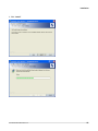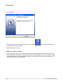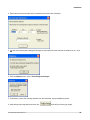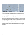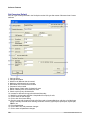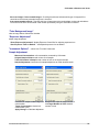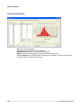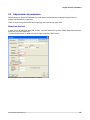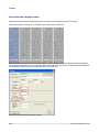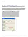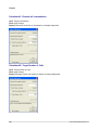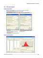
1
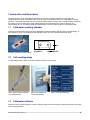
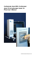
Cellometer Auto M10, Cellometer
Auto T4 & Cellometer Auto T4
Plus User Manual
© 2010 Nexcelom Bioscience LLC
The Cellometer Auto is a high precision imaging instrument. If you have difficulty concerning
operation or installation, please contact Customer Service at Nexcelom Bioscience LLC. Do not
attempt to service this instrument yourself. The warranty registration must be completed and returned
to Nexcelom Bioscience LLC within fourteen (14) days of purchase.
Customer Service
Nexcelom Bioscience LLC
360 Merrimack St. Bldg. 9
Lawrence, MA 01843
www.nexcelom.com
Phone: 978-327-5340
Fax: 978-327-5341
Email: [email protected]
Warranty
Nexcelom warrants that Nexcelom instrumentation products shall, for a period of one year from the
date of purchase, be free of any defect in material and workmanship. The sole obligation of this
warranty shall be to either repair or replace at our expense the product, at manufacturers option. The
original sales receipt must be supplied for warranty repair.
Products, which have been subjected to abuse, misuse, vandalism, accident, alteration, neglect,
unauthorized repair or improper installation, will not be covered by warranty.
Any Product being returned is to be properly disinfected and packaged (in original packing if
possible). Damage sustained in shipping due to improper packing will not be covered by warranty.
A valid Return Material Authorization Number (RMA#) is required for all warranty repairs. For RMA
instruction, please contact our customer service department.
License Agreement
This agreement states the terms and conditions upon which Nexcelom Bioscience LLC (Nexcelom)
offers to license to you the software together with all related documentations. The Software is licensed
to you for use only in conjunction with Nexceloms family of products.
Limited Liability (Hardware and Software)
Cellometer Auto T4 and M10 instruments and chambers are intended for research use only.
In no event shall Nexcelom be liable for any damages whatsoever (including, without
limitation,incidental, direct, indirect, special or consequential damages, damages for loss of business
profits,business interruption, loss of business information) arising out of the use or inability to use this
Software or related Hardware.
Note: This equipment has been tested and found to comply with the limits for a Class A digital device,
pursuant to part 15 of the FCC Rules. These limits are designed to provide reasonable protection
against harmful interference when the equipment is operated in a commercial environment. This
equipment generates, uses, and can radiate radio frequency energy and, if not installed and used in
accordance with the instruction manual, may cause harmful interference to radio communications.
Operation of this equipment in a residential area is likely to cause harmful interference in which case
the user will be required to correct the interference at his own expense.
Table of Contents
Part I Introduction and Description
8
1
Cellometer counting
...................................................................................................................................
chamber
9
2
9
Cell counting...................................................................................................................................
steps
3
................................................................................................................................... 9
Cellometer software
Part II Getting Started
1
12
Installation ................................................................................................................................... 13
Incoming inspection
.......................................................................................................................................................... 13
Software installation
.......................................................................................................................................................... 13
Take background
image
..........................................................................................................................................................
18
2
Set up Cellometer
...................................................................................................................................
Auto for cell counting
20
Prepare cell solution
.......................................................................................................................................................... 20
Load cells into counting
chamber
..........................................................................................................................................................
20
Insert chamber into
Cellometer Auto
..........................................................................................................................................................
21
Adjust focus
.......................................................................................................................................................... 21
Count cells
.......................................................................................................................................................... 22
Review results .......................................................................................................................................................... 22
Recount Images.......................................................................................................................................................... 22
Save data
.......................................................................................................................................................... 22
Save images
.......................................................................................................................................................... 22
Analysis
.......................................................................................................................................................... 22
Part III Software Features
1
24
Cellometer software
...................................................................................................................................
panel
25
Buttons and controls
.......................................................................................................................................................... 26
2
User input
.......................................................................................................................................................... 26
Output
.......................................................................................................................................................... 26
Cellometer software
...................................................................................................................................
menu items
27
File
.......................................................................................................................................................... 27
Cell type
.......................................................................................................................................................... 27
Options
.......................................................................................................................................................... 29
Analysis
.......................................................................................................................................................... 31
Help
.......................................................................................................................................................... 33
Part IV Operation Reference
36
1
Background...................................................................................................................................
image
37
2
................................................................................................................................... 37
Exposure adjustment
3
Manual adjustment
for cell counts
...................................................................................................................................
37
4
...................................................................................................................................
37
Set up new cell
type
5
Speed Count
................................................................................................................................... 38
6
................................................................................................................................... 38
Count new samples
© 2010 Nexcelom Bioscience LLC
5
Cellometer Auto M10, Cellometer Auto T4 & Cellometer Auto T4 Plus User Manual
7
Count from ...................................................................................................................................
saved images
38
8
Save images................................................................................................................................... 38
9
...................................................................................................................................
39
Multiple sample
histogram
10
...................................................................................................................................
39
Copy cell size
data and histogram
Part V Tutorial
42
1
Cell concentration
...................................................................................................................................
range
43
2
Test viability................................................................................................................................... 43
3
45
Set up a new...................................................................................................................................
cell type
4
Adjust cell size
parameters
...................................................................................................................................
46
5
47
Adjust dead...................................................................................................................................
cell parameters
6
Adjust decluster
parameters for clumpy cells
...................................................................................................................................
49
7
50
Turn on and...................................................................................................................................
off declustering for small cells
8
Sample adjustment
after cell couting
...................................................................................................................................
51
9
................................................................................................................................... 53
Cell size analysis
Part VI Appendix
56
1
Spectifications
................................................................................................................................... 57
2
...................................................................................................................................
57
Computer check
procedure
Check computer..........................................................................................................................................................
operating system
58
IT details for Cellometer
Counters
..........................................................................................................................................................
58
6
© 2010 Nexcelom Bioscience LLC
Introduction and Description
Introduction and Description
Introduction and Description
8
© 2010 Nexcelom Bioscience LLC
1 Introduction and Description
The basic principle of the Cellometer® automatic cell counter is imaging cytometry. It is the same as
hemacytometer in terms of spreading cells into a thin layer of liquid, which is done in a disposable counting
chamber. Cellometer automates the cell counting by taking images of cells in the counting chamber, analyzing
the number of cells in each image using imaging analysis, and converting the number of cells into cell
concentration per ml. The total counting area is equivalent to all four corner squares of a hemacytometer.
1.1
Cellometer counting chamber
Cellometer counting slide consists of two independent enclosed chambers with precisely controlled height. A
cell suspension of 20 µl is pipetted into the chamber through one of the sample introduction ports.
Cellometer disposable counting chamber.
1.2
Cell counting steps
The following are three steps to use the Cellometer Auto for cell counting.
Step 1. Pipette cells into Cellometer
cell counting chamber
1.3
Step 2. Insert chamber into
Cellometer instrument
Setp 3. Count cell automatically
Cellometer software
Cellometer Auto Counter software controls Cellometer instruments and acquires, analyzes and saves cell image
and concentration data.
© 2010 Nexcelom Bioscience LLC
9
Getting Started
Getting Started
Getting Started
12
© 2010 Nexcelom Bioscience LLC
2 Getting Started
This section helps you to get started using the Cellometer Auto systems for cell counting.
2.1
Installation
This section goes through the complete procedure of installation of Cellometer Auto Counter.
The instrument should be unpacked and inspected for mechanical damage upon receipt. Mechanical inspection
involves checking for signs of physical damage such as: broken knobs, etc. If damage is apparent contact
dealer or Nexcelom Bioscience LLC.
All Nexcelom Bioscience LLC products are carefully inspected prior to shipment and all reasonable precautions
are taken in preparing them for shipment to assure safe delivery.
Unpack Check List
•
•
•
•
•
•
•
Cellometer Auto instrument
Software CD disk
Cellometer Auto power converter
USB cable
Getting Started Reference Guide
User manual
CHT4 counting chambers (Shipped separately)
System requirements
Windows 2000, Windows XP, Vista, Windows 7 or higher
1.6 GHz or higher speed processor
2GB RAM recommended
USB 2.0 Port
© 2010 Nexcelom Bioscience LLC
13
Getting Started
Installation procedure
A. Check computer system
The computer operating system (Windows 2000, XP, Vista, 7 or higher), USB 2.0 port, user account with
administrator privileges are essential for the installation of Cellometer Auto Counter software.
B. Cellometer Auto Counter software installation
1. Insert Cellometer Auto Counter software disk into CD drive (the following images are screenshots using
Windows XP, these may appear slightly different depending on the version you are using.)
2. Click “Next”
14
© 2010 Nexcelom Bioscience LLC
Installation
3. Click “Install”
© 2010 Nexcelom Bioscience LLC
15
Getting Started
4. Click "Finish"
5. The Cellomter Auto Counter icon will appear on your desktop
and is ready for launching the
Cellometer Auto Counter software.
6. Remove disk from CD drive.
C. USB driver software installation
1. Connect power to Cellometer Auto instrument and turn on power switch located on the back of the unit.
2. Connect the USB cable between Cellometer Auto instrument and a USB 2.0 port on the computer. (Make
sure that Cellometer Auto Count software installation is complete before connecting the USB cable.) The
following process will start automatically.
16
© 2010 Nexcelom Bioscience LLC
Installation
3. Select the option "Yes, this time only"
4. Click “Next”
5. Select “Install the software automatically (Recommended)”
6. Click “Next”
© 2010 Nexcelom Bioscience LLC
17
Getting Started
7. Click “Continue Anyway”
8. Click “Finish”
Note: some computer systems may require USB driver installation for a second time. If so, repeat steps 3
through 7, if prompted.
A background image is a blank image of the system itself without the counting chamber. It is used to normalize
the cell counter and is taken at the time of system installation. Unless the instrument is moved, there is
generally no need to take a background image before cell counting.
1. Start Cellometer Auto Counter software by clicking the
18
icon on your desktop.
© 2010 Nexcelom Bioscience LLC
Installation
2. Enter instrument serial number which is located on the back of the Cellometer.
3. You will see a warning that a background image must be taken if this the first time the software is run. Click
OK.
4. From the Options menu, select “Take Background Image”.
5. If necessary, remove the counting chamber from the instrument, then press OK to proceed.
6. After background image has been taken click
© 2010 Nexcelom Bioscience LLC
, and verify a uniform gray image.
19
Getting Started
2.2
Set up Cellometer Auto for cell counting
This section goes through the complete procedure of counting a cell sample.
You need to prepare the following sample.
1. Cell sample concentration range corresponding to instrument:
• Auto T4: 2.5 x 10⁵ to 1.0 x 10⁷ cells/mL
• Auto M10: 5x10⁵ to 2.0 x 10⁷ cells/mL
2. 0.2% trypan blue when viable cell count is required (0.2% trypan blue is made by diluting 0.4% trypan blue
with PBS prior to use).
1. Place cell counting chamber on a fresh Kimwipe.
2. Label slide chamber #1 and chamber #2 on the white margin of the chamber. Take care to make sure the
clear portion of the counting chamber are not touched.
3. Prepare cells by inverting cell containing tube 10 times, pipetting up and down 10 times. Do not shake!
Shaking sample will generate bubbles.
4. Stain cells with trypan blue when viable cell count is required. Take 50 μl or more cell suspension for mixing
with trypan blue.
5. Take 20 μl cell suspension after further mixing to load chamber #1. Immediately take another 20 μl cell
suspension and load chamber #2.
Load counting chamber by touching pipette tip to a sample introduction port and then pipette.
Capillary force automatically spreads the cell sample within the counting chamber.
20
© 2010 Nexcelom Bioscience LLC
Set up Cellometer Auto for cell counting
Hold the loaded chamber in the white area and stay away from the clear optical window area.
Insert the loaded chamber into Cellometer Auto sample slot, and gently push the slide to the stop. The
instrument will count and analyze only the chamber inside the system. To measure the second chamber,
remove the slide from Cellometer Auto, turn around the slide, and insert the second chamber in the instrument.
The first time when you use Cellometer Auto, make sure the focus adjustment is correct. After initial setup,
Cellometer Auto should do the majority of the counting operation without needing to re-focus.
Procedure to adjust focus
1. Turn on power switch. Start Cellometer Auto Counter software.
2. Place counting chamber with cells into Cellometer Auto by inserting the chamber until touching the internal
stop. The chamber inside the instrument is the one which will be counted.
3. Click the
button.
4. Slowly turn "Focus Knob" and allow cell image to be displayed on the computer. Adjust Knob until best cell
counting focus is achieved: live cells have a bright center and a clear defined edge.
Prior to counting cells for the first time, a background image should be taken:
5. Remove counting chamber
6. From the Options menu, select “Take Background Image”.
7. Click OK to proceed
This does not need to be done for subsequent uses.
© 2010 Nexcelom Bioscience LLC
21
Getting Started
Click "Count" button while the cell image is displayed. ("Display Image" button must be pressed first to enable
"Count" button.) The progress bar at the bottom of the software panel indicates counting in progress. A
numeric counter also displays updated cell counts.
Cell counting data are displayed in the left section of the software panel. Cell count, mean diameter, and cell
concentration are displayed. When the "Test Viability" selection is checked, results are for live cells only, and a
percentage viability is reported as well. The percentage viability is calculated as live cell count as a percentage
of total cell count, including live and dead cells.
If you would like to change your parameters you can utilize this Recount Image icon to recount your cell sample.
This step can only be completed before you save your data.
Cell counting results can be saved into a data file. The data file name is displayed at the lower left corner of the
software panel. To change the data file, use menu item File->New Data File. Click Save Data button to save
data. Click View Saved Data button to view saved data in the currently selected data file.
Images can be saved by using menu item File->Save Images. The software automatically saves all images that
are collected for cell counting. The destination folder for the images can be selected through the file selector.
Data analysis features include a sample adjustment calculator and a cell size analysis panel. Based on the
measured cell concentration, adjustment is calculated for desired target concentration or cell number. Also,
after each cell counting, cell sizes and distribution histogram are provided. Select menu item "Analysis" for
these features.
22
© 2010 Nexcelom Bioscience LLC
Software Features
Software Features
Software Features
24
© 2010 Nexcelom Bioscience LLC
3 Software Features
This section describes software features of Cellometer Auto Counter software.
3.1
Cellometer software panel
1) Display Image button: display image of cells in Cellometer chamber
2) Count button: capture image and count cells
3) Test Viability check box: when checked, count live and dead cells in one operation
4) Cell Type: cell name, and cell counting parameters
5) Sample ID: sample name from user
6) Dilution: adjust to determine concentration of original sample prior to dilution with e.g. trypan blue
7) (Live) Cell Count: total number of (live) cells
8) Dead Cell Count: total number of (dead) cells
9) Mean Diameter: mean diameter of live cells estimated from cell image in microns
10) Viability (%): percentage of live cells to total cells
11) (Live) Cell Concentration: (live) cell concentration (/ml) = Dilution Factor x (Live) Cell Count / Volume
12) Recount: count a set of captured images again after modifying counting parameters
13) Select Data File: set the name and location of a data file where counting results can be stored
14) Save Data button: save date, time, sample ID and counting data into a text file
15) View Saved Data button: display and print cell counting data from a saved file
16) Stop button: stop counting, please wait for response
17) Calculate Concentration Adjustment: launch the Sample Adjustment calculator
18) Show Cell Size Distribution: open the Cell Size Analysis window
19) Export Results to Excel: optionally save captured and counted images as well as counting parameters to
an Excel file
20) Print Results: send counting results to printer
21) Cell image display: display cell images
22) Counted check box: when checked, mark the counted cells with an outline
23) Count In View: number of cells counted in the displayed image
© 2010 Nexcelom Bioscience LLC
25
Software Features
24) # of live and dead cells: + or - number of live or dead cells for manual adjustment
25) Manual Adjustment Enter: adjust number of cells based on manual inspection
26) Get Help button: direct access to user manual, on-line resources, video tutorials and contact with
Applications Specialist. Requires internet connection.
"Display Image" button
display image of cells in Cellometer chamber
“Count” button
capture image and count cells
“Speed Count” button
“Count” button changes into “Speed Count” when Speed Count option is selected
“Save Data” button
save Date, Time, Cell Type, Sample ID, Live Cell Count, Viability, Mean Diameter, Dilution Factor, Live Cell
Concentration into a text file
“Manual Adjustment Enter”
adjust number of cells based on manual inspection
“Counted” check box
when checked, mark the counted cells
“Viability” check box
when checked, count live and dead cells
“Details” check box
when checked, show panel for images
“Cell Type”
define the cell name, and cell counting parameters
“Sample ID”
sample name from user
“Dilution”
adjust to determine concentration of original sample prior to dilution with e.g. trypan blue
“(Live) Cell Count”
total number of (live) cells
“Viability”
% of live cells to total cells
“Mean Diameter”
mean diameter of live cells estimated from cell image in microns
“(Live) Cell Concentration”
(live) cell concentration (/ml) = Dilution Factor x (Live) Cell Count / Volume
“Count In View”
number of cells in the display
26
© 2010 Nexcelom Bioscience LLC
Cellometer software panel
3.2
Cellometer software menu items
Load Image for Display
Load one image from saved Cellometer Auto images for display only
Load Image and Count
Load two saved Cellometer Auto images for counting. One Cellometer Auto image can be used twice.
New Data File
Change to a different data file or name a new data file where Cellometer Auto counting data is saved.
Open Data File
Open an existing data file where counting results can be saved
Save Image
Save Cellometer Auto images from measurement location A and B in bitmap format
Save Counted Images
Save captured images after counting with counted cells outlined
Print Results
Send counting results to a printer
Export Results to Excel
Optionally save captured and counted images as well as counting parameters to an Excel file
Exit
Quit Cellometer Auto Counter software
Cell Type Wizard
Use New Cell Type Wizard to set up a new cell type
Import/Export
Import or export a new cell type from the cell type library
New Cell Type
Start a new cell type using manual method
Edit Cell Type
Change parameters for the Cell Type currently selected in the Sep Up box
Delete Cell Type
Delete Cell Type currently selected in the Sep Up box
© 2010 Nexcelom Bioscience LLC
27
Software Features
Set Current as Default
Set Cell Type currently selected in the Set Up box as the Cell type after restart Cellometer Auto Counter
software.
1. Cell type name
2. Cell type description
3. Minimum cell diameter that is counted
4. Maximum cell diameter that is counted
5. Roundness of the cells that are counted
6. Contrast of cells counted
7. Define degree of dark center for dead cell count
8. Define uniformity with cell for dead cell count
9. Check to pick up very dim dead cells
10. Increase to decluster clumpy cells with weak boundary
11. Modify for cell boundary definition. Keep default for majority of cells.
12. Click to save as new cell type
13. Click to lock from future editing
14. Check to count cell clumps as single cells. May need to increase Maximum cell size to include larger
clumps. Normally checked when counting small cells such as lymphocytes, splenocytes, thymocytes,
PBMCs, etc.
15. Print captured data
16. Click to NOT save cell parameter changes
17. Click to save cell parameter changes
28
© 2010 Nexcelom Bioscience LLC
Cellometer software menu items
“Counting Options”
Count All - count all cells in total areas
Speed Count - stop counting after reaching user defined number of cells or images have been counted
Stop Counting Over - upper limit of cell number for Speed Count
Intelligent File Load - Automatically load all saved images in a file for a given sample
Show Dead Cell Count- Allows you to view all of the dead cell in your sample.
Start Program With Last Counted Cell Type - when checked, the default Cell Type will be the last Cell
Type that was used before exiting the software
Start Program with a Dilution of - Set a default dilution factor.
© 2010 Nexcelom Bioscience LLC
29
Software Features
"Save Options"
Set sample ID as cell type: Checking this box will auto input the Sample ID to match the Cell Type
parameter name being used for counting.
Time stamp sample ID: Checking this box will auto append the Sample ID with the date and time the count
was performed.
Auto increment sample ID: Checking this box will auto append the Sample ID with an incremental numerical
value. Example: CHO sample_001
Include Instrument ID in file: Checking this box will auto append the Instrument ID to the sample ID after the
count is performed.
Log user name: Checking this box will require the user to enter in an ID that will be recorded with the data.
Auto save data.txt: Checking this box will auto save the data into the Data.txt file after a count is performed.
Create new Data.txt with each sample: Checking this box will auto create a new data.txt file for each
sample and save the counting results to it after a count is performed.
Set Folder: These buttons bring up the File Dialog Window which allows the user to specify where the data.
txt, images and/or Excel files will be saved when Auto Save boxes are checked.
Auto save sample image: Checking this box will auto save the images to the folder specified using the Set
Folder command.
30
© 2010 Nexcelom Bioscience LLC
Cellometer software menu items
Save raw images / Save counted images: Checking these boxes indicate which type of images will be
saved when the Auto save sample image box is checked.
Auto export sample to Excel: Checking this box will auto export the counting data, results and calculations
into an Excel file which will be saved in the location specified by using the Set Folder command.
“Take Background Image”
take an image without Cellometer chamber
“Exposure Adjustment”
adjust image brightness
“Show Exposure Adjustment”- display Exposure Control Bar for adjusting exposure time
“Save Exposure Time As Default” - set adjusted exposure time as default
"Instrument Options" - select Auto T4 or M10 instrument
Sample Adjustment
Measured Concentration: cell concentration measured by Cellometer
Original Sample Volume: total volume of cell sample
Total Cell Number in Sample: total number of cells in the original sample
Sample Adjustment: instructions for sample adjustment to obtain desired results
Calculator #1: adjust to obtain target cell Calculator #2: adjust for target number of
concentration
cellsTarget Number of Cells: desired
Target Concentration: desired cell
number of cells
concentration (/mL)
Apply Change: to calculate adjustment
© 2010 Nexcelom Bioscience LLC
31
Software Features
Show Size Distribution
Print: print cell size histogram
Save As: save cell diameter values to a data file
Open Diameter File: open an existing cell diameter file
Multiple: check to load and display multiple cell diameter files (up to 5)
Copy to Clipboard: copy diameter data and histogram to Clipboard. This data can be pasted
into a Word, Excel or PowerPoint document
32
© 2010 Nexcelom Bioscience LLC
Cellometer software menu items
This menu item includes the following functions.
Help Contents
The online help consists of instructions for operating Cellometer Auto Counter and software references.
Contact Support and Training
Launches Nexcelom’s online resources page, which contains: video tutorials, submit a support ticket with
sample images, and access to FAQs and Application notes. (Internet connection required)
About Cellometer Auto Counter
Displays version number of Cellometer Auto software currently installed.
All of these support pages can also be accessed by simply clicking the "Get Help" button
bottom right hand side of the Cellometer software.
© 2010 Nexcelom Bioscience LLC
located on the
33
Operation Reference
Operation Reference
Operation Reference
36
© 2010 Nexcelom Bioscience LLC
4 Operation Reference
This section describes recommended procedures to perform some routine operations with Cellometer Auto
Counter software.
4.1
Background image
Use the following steps for this function.
1. Place a Cellometer chamber with cells into Cellometer Auto instrument
2. “Display Image”
3. Focus if necessary
4. Remove Cellometer chamber from Cellometer Auto instrument
5. Options -> Take Background Image
6. Wait until the Background Image is saved
7. Click OK
4.2
Exposure adjustment
Use the following steps for this function.
1. Options -> Exposure Adjustment -> Show Exposure Adjustment
2. Slide Exposure Adjustment Bar to change exposure time for current measurement
3. Options -> Exposure Adjustment -> Save Exposure Time As Default when desired
4.3
Manual adjustment for cell counts
Use the following steps for this function.
1. Enable Counted
2. Click high resolution panels 1 through 4
3. Type # of cells to change next to “Enter” button
4. Push “Enter” button
5. Modified cell count is displayed in the “Cell Count”
6. Modified cell count is used to calculate “Live Cell Concentration”
In case there are too few cells to count by Cellometer Auto, cell concentration is estimated by:
1. Click "A" and "Counted"
2. Manual count cells in "A"
3. Input the number of cells in "Manual Adjust" then "Enter"
4. Estimated cell concentration will be displayed in "Cell Concentration"
4.4
Set up new cell type
Use the following steps for this function.
1. Place a Cellometer chamber with new cells into instrument
2. "Display Image” (Make sure cells are focused)
3. File -> Save images
4. Cell Type -> New Cell Type
5. Type cell name
6. File -> Load image and Count
7. View images in the high resolution panels (1 to 4)
© 2010 Nexcelom Bioscience LLC
37
Operation Reference
8. Cell Type -> Edit Cell Type to modify cell type parameters.
9. Recount the same images using edited cell type parameter
10. Repeat steps 6 through 9 when necessary
4.5
Speed Count
Use the following steps for this function.
1. Options -> Counting Options -> Speed Count
2. Input the number above which count will stop
3. Counting stops at the frame after the upper number is reached
4. Input the number of images
5. The counting stops after the upper image limit is reached
4.6
Count new samples
Use the following steps for this function.
1. Pipette cells into Cellometer chamber
2. Start Cellometer software
3. Place Cellometer counting chamber in instrument
4. “Display Image”
5. Focus when necessary
6. Select “Cell Type”
7. Input sample ID and Dilution factor
8. Click “Count”
9. Save data if desired
10.Save image if desired
To stop cell counting, click "STOP" button. The software must complete counting a frame before it stops, so
there is a short delay before counting is stopped.
4.7
Count from saved images
Use the following steps for this function.
1. File -> Load Image and Count
2. Select the first image file. Note- If you previously checked the Intelligent file load box under counting
options you will only need to select the first image. The remaining images will load automatically.
3. Select the second image file
4. Counting will start automatically
4.8
Save images
Use the following steps for this function.
1. Place a Cellometer chamber with cells into Cellometer Auto instrument
2. “Display Image”
3. Focus if necessary
4. File -> Save Images
5. Select location for image files
6. Input prefix portion of the filename
7. Click Save
If the image is intended for further analysis using Cellometer Auto Counter software, do not change file name.
38
© 2010 Nexcelom Bioscience LLC
Multiple sample histogram
4.9
Multiple sample histogram
Use the following steps for this function.
1. Analysis -> Cell size analysis
2. Check "Multiple"
3. Open Diameter File
Open first saved cell diameter file
Open second saved cell diameter file
....
(up to 5 diameter files)
4. Histogram of multiple sample is ready to be copied on clipboard
4.10 Copy cell size data and histogram
Use the following steps for this function.
1. Open Word or Excel file
2. Analysis -> Cell size analysis
3. Open Diameter File (if the desired data is not the current counting results)
4. Copy to Clipboard
5. Go to Word or Excel file
6. Edit ->Paste to paste cell diameter distribution data or
Edit -> Paste Special -> Picture to paste histogram
© 2010 Nexcelom Bioscience LLC
39
Tutorial
Tutorial
Tutorial
42
© 2010 Nexcelom Bioscience LLC
5 Tutorial
This section includes several tutorials to illustrate how to perform some routine functions with Cellometer Auto
Counter.
5.1
Cell concentration range
Cell sample concentration range corresponding to the instrument:
• Auto T4: 2.5 x 10⁵ to 1.0 x 10⁷ cells/mL
• Auto M10: 5.0 x 10⁵ to 2.0 x 10⁷ cells/mL
If the cell concentration is too high, counting results are not reliable due to clumping of cells.
Inspect displayed live image to make sure cell sample in the counting chamber fits the proper concentration
range.
After counting, use "Counted" to review counting results.
5.2
Test viability
Cellometer Auto is used to count total cells or viable cells depending on user's selection.
For best viable cell measurement, 0.2% trypan blue is used to stain cells.
To prepare 0.2% trypan blue stock solution:
1. Dilute standard trypan blue, typically at 0.4%, with PBS (or other solutions used with your cells)
2. Make sure trypan blue does not have microscopic crystals, as shown in the figure below
The stock solution can be stored at room temperature.
If your cell images contain small trypan blue crystals, filter your solution through a 0.2 μm filter.
Example image showing small trypan blue crystals (indicated by arrows) that need to be filtered for accurate cell counting.
Viable cell concentration and viability measurement procedure
1. Make 0.2% trypan blue stock solution
2. Stain cells with 0.2% trypan blue solution (1:1 for dilution factor of 2)
3. Load the counting chamber
4. Check "Test Viability" on Cellometer software
© 2010 Nexcelom Bioscience LLC
43
Tutorial
5. Enter in dilution factor
6. Count cells
7. Output displays "Live Cell Concentration" (cells/ml), and "Viability" (%)
8. Check "Counted"
Live cells are indicated by green outlines, and dead cells are indicated by red outlines, as seen in the figure (b)
below.
MCF7 cell viability measurement using Auto T4: (a) MCF7 cell image and (b) counted MCF7 cells.
44
© 2010 Nexcelom Bioscience LLC
Test viability
5.3
Set up a new cell type
Method 1: Import from Cell Library
Import pre-existing cell type parameters from Cell Library installed with Cellometer Auto Counter software
1. Cell Type
2. Import Cell Type
3. Select Cell Type from Cell Type in Cell Library
4. Click “>>”
5. Click “OK”
6. Review selected Cell Type in the “Set Up” “Cell Type” drop down menu
Method 2: Use New Cell Type Wizard
Follow interactive instructions to set up new cell type parameters using saved or live cell images
1. New Cell Type Wizard
2. Select Using Live or Saved Image
Live Image is used when Auto T4 is loaded with the counting chamber with cells.
Saved Image uses saved Auto T4 cell images.
3. Process images to initiate cell parameters
4. Input Cell Type Name
5. Process cell images to establish cell type parameters
6. Visual inspection
• Click “Counted”
• Click through “1” to “4”
• Visually inspect cell image and “counted” image with green, red and yellow outlines
• Adjust parameters and recount the same sample
• (See adjust cell type parameter and adjust dead cell parameters for details)
Method 3: Send new cell images to Nexcelom
To send new cell images to Nexcelom click the “Get Help” button
on your Software and select “Go”
under Submit a support ticket. From here you can upload your images and have them directly sent to the
Nexcelom Support Team.
© 2010 Nexcelom Bioscience LLC
45
Tutorial
5.4
Adjust cell size parameters
For each cell type, "Cell Diameter Max." and "Cell Diameter Min." are the maximum and minimum cell sizes
respectively.
Cell parameters for HT-29 cell. Arrows point to cell size parameters.
When cell size parameters are not set up properly, Cellometer software displays graphical indicators. Figure
below show counted cells for the same HT-29 image, using difference cell size parameters.
HT-29 cell counting results measured using different cell size parameters. (a) "Cell Diameter Min." size is too large. Cells smaller
than 15 μm are not counted, as indicated by missing outlines. (b) "Cell Diameter Max." is too small. Cells larger than 16 μm are not
counted, as indicated by the yellow outlines. (c) Both "Cell Diameter Min." and "Cell Diameter Max." are set up properly to include
all cells. (d), (e) and (f) are respective cell size histograms for (a), (b), and (c). They are also used to establish cell size parameters.
46
© 2010 Nexcelom Bioscience LLC
Adjust cell size parameters
5.5
Adjust dead cell parameters
Default settings of “Dead Cell Parameters” provide fastest counting speed for standard cell types that are
stained solid dark blue by trypan blue.
There are some cell types with different morphology when stained with trypan blue.
Weak blue dead cell
In order to pick up weak blue dead cells, activate “Very Dim Dead Cells” by check “Modify Dead Cell Parameter”
and check “Very Dim Dead Cells”.
"Contrast Enhancement" for dead cells can be higher than that of the live cells.
Cell parameters for Cos7. "Very Dim Dead Cells" is checked
© 2010 Nexcelom Bioscience LLC
47
Tutorial
Dead cells with a brighter center
Dead cells of this type have small bright centers, as shown in the following figure for CHO cells.
Dead cell parameter "Sensitivity" is modified to pick up this type of dead cell.
CHO cell counting results with different "sensitivity" settings. (a). CHO cell image, (b) to (e) sensitivity of the dead cell parameter
was increased incrementally from 1 to 4, respectively. Green outlines indicate live cells while red outlines indicate dead cells. Both
live and dead cell counts in (e) agree with visual observation of cell image in (a).
CHO cell parameters with high "Sensitivity" settings.
48
© 2010 Nexcelom Bioscience LLC
Adjust dead cell parameters
5.6
Adjust decluster parameters for clumpy cells
For decluster function, there are two parameters used by Cellometer software to separate cells connected to
each other. They are "Decluster Edge Factor" and Decluster threshold factor ("Decluster Th Factor"). The
default settings of "Decluster Edge Factor" and "Decluster Th Factor" are 0.5 and 1.0, respectively.
For the majority of cell types, default settings are adequate to separate clumpy cells. However, some cell types,
such as MCF7, PC12, contain cells having dim boundaries within the clump. In this case, decluster parameters
are modified to separate them.
Example: Clumpy MCF7 cells
MCF7 cells are measured using both default and modified decluster settings.
MCF7 cell counting results (a) with default Decluster setting, and (b) With modified settings.
As seen in the above figure (a), when default decluster settings are used, cells within clumps are not fully
separated, resulting in MCF7 concentration of 6.5 x 10⁵ cell/ml. When modified declustering settings are used,
cells within the clumps are separated. The resulting MCF7 concentration is 8.3 x 10⁵ cell/ml.
MCF7 cell type parameters modified for clumpy cells with dim boundaries within clumps.
© 2010 Nexcelom Bioscience LLC
49
Tutorial
5.7
Turn on and off declustering for small cells
Examples of small cells are mouse splenocytes, lymphocytes, thymocytes and PBMCs. Their diameters are
typically less than 7 μm.
For really small cells, Cellometer Auto focus may influence cell counting when the decluster feature is activated.
The following figures show mouse thymocyte counting results, (a) with decluster, and (b) without decluster. The
green outlines indicate counted cells. When decluster is turned off by selecting "No Decluster", more cells are
counted.
Mouse thymocyte counting results, (a) with Decluster, and (b) without Decluster.
Mouse thymocyte parameters for cell counts less than 1300.
50
© 2010 Nexcelom Bioscience LLC
Turn on and off declustering for small cells
However, some samples contain clumpy cells, as shown in the following figure (a). Other samples have very
high cell concentration, as shown in 3.7.3 (b). For these samples, Decluster is activated, and Contrast
Enhancement is reduced.
Cell type parameters for high concentration or clumpy small sized cells.
5.8
Sample adjustment after cell couting
Measured Concentration (cells/ml)
Cell concentration just measured by Auto
Original Sample Volume
Cell sample volume
Total Cell Number in Sample
Total number of cells in the original sample
© 2010 Nexcelom Bioscience LLC
51
Tutorial
Calculator #1: Desired cell concentration
Input: Target Concentration
Click: Apply Change
Display: Instruction for dilution or concentration in Sample Adjustment
Calculator #2: Target Number of Cells
Input: Target Number of Cells
Click: Apply Change
Display: Pipetting volume and number of aliquots in Sample Adjustment
52
© 2010 Nexcelom Bioscience LLC
Sample adjustment after cell couting
5.9
Cell size analysis
Sample Adjustment
Measured Concentration: cell concentration measured by Cellometer
Original Sample Volume: total volume of cell sample
Total Cell Number in Sample: total number of cells in the original sample
Sample Adjustment: instructions for sample adjustment to obtain desired results
Calculator #1: adjust to obtain target cell Calculator #2: adjust for target number of
concentration
cellsTarget Number of Cells: desired
Target Concentration: desired cell
number of cells
concentration (/mL)
Apply Change: to calculate adjustment
Show Size Distribution
© 2010 Nexcelom Bioscience LLC
53
Tutorial
Print: print cell size histogram
Save As: save cell diameter values to a data file
Open Diameter File: open an existing cell diameter file
Multiple: check to load and display multiple cell diameter files (up to 5)
Copy to Clipboard: copy diameter data and histogram to Clipboard. This data can be pasted
into a Word, Excel or PowerPoint document
54
© 2010 Nexcelom Bioscience LLC
Appendix
Appendix
Appendix
56
© 2010 Nexcelom Bioscience LLC
6 Appendix
6.1 Spectifications
Cellometer Auto is an imaging instrument that acquires cell data from multiple locations of the Cellometer
counting chamber. It is connected to a computer via USB 2.0 port.
Instrument Specifications
Weight: 9 lb ( 4 kg)
Size: 3.5 in x 4 in x 12.5 in ( 9 cm x 10 cm x 32 cm )
Wall Adaptor: 100-240 AC, 50-60 Hz, 0.5 A
Power to instrument : 12 V DC, 1.5 A Max
6.2
Computer check procedure
This is a procedure to check computer hardware, operating system and setup for Cellometer Auto cell counter.
Computer System Recommendations and Requirements
Windows 2000, Windows XP (SP2 or SP3), Vista, Windows 7 or higher.
1.6 GHz or higher speed processor
2GB RAM recommended
USB 2.0 Port
© 2010 Nexcelom Bioscience LLC
57
Appendix
a. On your PC, go to Start->Control Panel
b. Double click “System”
The operating System must be Windows 2000, Windows XP (SP2 or SP3), Vista, Windows 7 or higher for
Cellometer Auto Counter software to run.
Installed file locations
Program Files
• File location for default settings on English Windows XP and Windows Vista or Windows 7: “C:\Program
Files\Nexcelom\”
• On installation CD: “\program files\Nexcelom\”
Files:
MFC42D.dll
MFCO42D.dll
MFCRTD.dll
NexcelomIcon.ico
Subfolders:
\Auto – Contains the software binary
Files:
Cellometer.exe
58
© 2010 Nexcelom Bioscience LLC
Computer check procedure
\Cell Samples – Contains sample images
Files:
AutoT4-HEK293-A.bmp
AutoT4-Hela-A.bmp
AutoT4-HT29_blue-A.bmp
AutoT4-Jurkat-A.bmp
AutoT4-SF9_blue-A.bmp
AutoT4-Vero-A.bmp
\Docs
Files:
CellometerAutoCounter.pdf – Software manual in .pdf form
\Drivers – This folder contains a copy of the AutoT4/M10 USB drivers.
Data Files
IMPORTANT-Users need read/write access to this folder
• File location for default settings on English Windows XP: hidden folder “C:\Documents and Settings\All
Users\Application Data\Nexcelom_Auto\ “
• File location for default settings on English Windows Vista or Windows 7: hidden folder “C:
\ProgramData\Nexcelom_Auto\”
• On installation CD: “\CommonAppData\Nexcelom_Auto\”
Files:
AutoT4.ini - software settings and parameters (users need read/write on this file).
cellbank.txt - cell library provided by Nexcelom to customer (users need read access).
cellbankM10.txt - cell library provided by Nexcelom to customer (users need read access).
CellometerAutoCounter.chm - The help file (If having problems with Help Menu “Online Help”, copy this file
to the “Program Files\Nexcelom” folder.)
celltypes.txt - cell library created by the user (users need read/write on this file).
celltypesM10.txt - cell library created by the user (users need read/write on this file).
NoImageBackground.bmp - software component (users need read on this file).
background.bmp - software component, generated by Cellometer software once the instrument is installed.
(users need read/write/create access on this file, other similar files that contain a serial number in the
name).
Subfolder:
\Deleted – Contains an archive of deleted cell types.
How to hand load the USB driver:
This should only be done by an IT professional with Administrator access to the machine.
1. Disconnect the instrument from the computer.
2. Locate the drivers folder in program files.
3. Go to the subfolder \Drivers\Lu170
4. Double Click uninstall.bat (This will clean existing drivers)
5. Go to the subfolder \Drivers\C1175
6. Double Click uninstall.bat (This will clean existing drivers)
7. Reboot the computer
8. Locate the drivers folder in program files.
9. Go to the subfolder \Drivers\Lu170
10.Double Click install.bat (This will install a fresh copy of the driver)
11.Go to the subfolder \Drivers\C1175
12.Double Click install.bat (This will install a fresh copy of the driver)
13.Reboot the computer
14.Plug the Cellometer back into the computer
15.Follow the instructions to install the drivers for a Cellometer.
© 2010 Nexcelom Bioscience LLC
59
Appendix
USB memory stick installs
It is often the case that installing from a USB memory stick will result in a failure to load USB drivers during
install and crash the install. If this happens, copy the install from the memory stick to the desktop of the
computer and install the software from the desktop location.
60
© 2010 Nexcelom Bioscience LLC
Customer Service
Nexcelom Bioscience LLC
360 Merrimack Street
Building 9
Lawrence, MA 01843, USA
Phone: 978-327-5340
Fax:
978-327-5341
Email: [email protected]
www.nexcelom.com
Rev. B