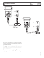
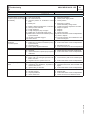
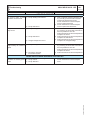
1
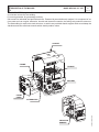
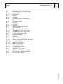
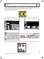
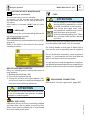
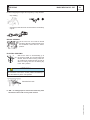
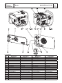
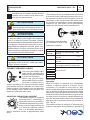
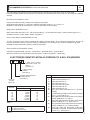
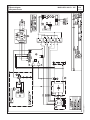
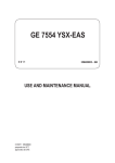
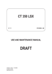
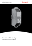
USE AND MAINTENANCE MANUAL MAGIC WELD 200 YD MAGIC WELD 200 YDE M A D E I N I T A L Y Codice Code Codigo Kodezahl 222719003 Edizione Edition Edición Ausgabe 02.2014 I GB F MAGIC WELD 200 YD - YDE DESCRIPTION OF THE MACHINE M 0 REV.0-02/14 The MAGIC WELD engine driven welder is a unit which ensures the dual function as: a) a current source for are welding b) current generator for generating auxiliary Unit meant for industrial and professional use. Powered by an endothermic engine; it is composed of various parts such as: engine, alternator, electric and electronic controls, the fairing at a protective structure. The assembling is made on a steel structure, on which are provided elastic support which must damp the vibrations and also eliminate sounds which would produce noise. CANOPY FRAME ENGINE BATTERY FRONT PANEL VIBRATION DAMPER 20/02/14 22270-GB ALTERNATOR M Quality system 01 REV.4-03/12 UNI EN ISO 9001 : 2008 The certifying institute, ICIM, which is a member ofthe International Certification Network IQNet, awarded the official approval to MOSA after anexamination of its operations at the head office andplant in Cusago (MI), Italy. This certification is not a point of arrival but a pledgeon the part of the entire company to maintain a levelof quality of both its products and services whichwill continue to satisfy the needs of its clients, aswell as to improve the transparency and thecommunications regarding all the company’s activesin accordance with the official procedures and inharmony with the MOSA Manual of Quality. The advantages for MOSA clients are: ·Constant quality of products and services at thehigh level which the client expects; ·Continuous efforts to improve the products andtheir performance at competitive conditions; ·Competent support in the solution of problems; ·Information and training in the correct applicationand use of the products to assure the security ofthe operator and protect the environment; ·Regular inspections by ICIM to confirm that therequirements of the company’s quality systemand ISO 9001 are being respected. All these advantages are guaranteed by the CERTIFICATE OF QUALITY SYSTEM No.0192 issued by ICIM S.p.A. - Milano (Italy ) - www.icim.it 10/10/02 M01-GB MOSA has certified its quality system according to UNI EN ISO 9001:2008 to ensure a constant, highquality of its products. This certification covers thedesign, production and servicing of engine drivenwelders and generating sets. Index M 0 M 01 M 1.01 M 1.1 M 1.4 M1.4.1 M 1.5 M 1.6 M 2 M 2.1 M 2.2 M 2.6 M 2.7 M3 M 6.21 M 6.22 M 20 M 21 M 22 M 31 M 34... M 34.3 M 37 M 38.10 M 38.12 M 39.6 M 40... M 43 M 45 M 55 M 60 M 61-….. MAGIC WELD 200 YD - YDE M 1 REV.0-02/14 DESCRIPTION OF THE MACHINE QUALITY SYSTEM COPYRIGHT NOTES CE MARK DECLARATION OF CONFORMITY TECHNICAL DATA TECHNICAL DATA ADVICE SYMBOLS SYMBOLS INSTALLATION AND ADVICE INSTALLATION UNPACKING AND TRANSPORT ASSEMBLING: CTM - MW 200-D ASSEMBLING: TRM - MW 200-D SET-UP FOR OPERATION ENGINE STARTING STOPPING THE ENGINE CONTROLS USE AS A WELDER PARALLEL ENGINE DRIVEN WELDER USE AS A GENERATOR REMOTE CONTROL REMOTE CONTROL ENGINE PROTECTION TROUBLE-SHOOTING MAINTENANCE STORAGE - CUST OFF RECOMMENDED ELECTRODES ELECTRICAL SYSTEM LEGENDE ELECTRICAL SYSTEM 20/02/14 22270-GB I GB F M 1.01 Copyright REV.0-10/02 ! ATTENTION This use and maintenance manual is an important part of the machines in question. The assistance and maintenance personel must keep said manual at disposal, as well as that for the engine and alternator (if the machine is synchronous) and all other documentation about the machine. We advise you to pay attention to the pages concerning the security (see page M1.1). All rights are reserved to said Company. It is a property logo of MOSA division of B.C.S. S.p.A. All other possible logos contained in the documentation are registered by the respective owners. + The reproduction and total or partial use, in any form and/or with any means, of the documentation is allowed to nobody without a written permission by MOSA division of B.C.S. S.p.A. To this aim is reminded the protection of the author’s right and the rights connected to the creation and design for communication, as provided by the laws in force in the matter. In no case MOSA division of B.C.S. S.p.A. will be held responsible for any damaga, direct or indirect, in relation with the use of the given information. 10/10/02 M1-01-GB MOSA division of B.C.S. S.p.A. does not take any responsibility about the shown information on firms or individuals, but keeps the right to refuse services or information publication which it judges discutible, unright or illegal. Notes M 1-1 REV.1-03/14 INFORMATION Dear Customer, We wish to thank you for having bought a high quality set. Our sections for Technical Service and Spare Parts will work at best to help you if it were necessary. To this purpose we advise you, for all control and overhaul operations, to turn to the nearest authorized Service Centre, where you will obtain a prompt and specialized intervention. + In case you do not profit on these Services and some arts are replaced, please ask and be sure that are used exclusively original parts; this to guarantee that the performances and the initial safety prescribed by the norms in force are re-established. INFORMATION OF GENERAL TYPE In the envelope given together with the machine and/or set you will find: the manual for Use Maintenance and Spare Parts, the manual for use of the engine and the tools (if included in the equipment), the guarantee (in the countries where it is prescribed by law). The Manufacturer shall not be liable for ANY USE OF THE PRODUCT OTHER THAN THAT PRECISELY SPECIFIED IN THIS MANUAL and is thus not liable for any risks which may occur as a result of IMPROPER USE. The Company does not assume any liability for any damage to persons, animals or property. Our products are made in conformity with the safety norms in force, for which it is advisable to use all these devices or information so that the use does not bring damage to persons or things. +The use of non original spare parts will cancel immediately any guarantee and Technical Service obligation. While working it is advisable to keep to the personal safety norms in force in the countries to which the product is destined (clothing, work tools, etc.). NOTES ABOUT THE MANUAL Before actioning the machine please read this manual attentively. Follow the instructions contained in it, in this way you will avoid inconveniences due to negligence, mistakes or incorrect maintenance. The manual is for qualified personnel, who knows the rules: about safety and health, installation and use of sets movable as well as fixed. Do not modify for any motive parts of the machine (fastenings, holes, electric or mechanical devices, others..) if not duly authorized in writing: the responsibility coming from any potential intervention will fall on the executioner as in fact he becomes maker of the machine. You must remember that, in case you have difficulties for use or installation or others, our Technical Service is always at your disposal for explanations or interventions. The manual for Use Maintenance and Spare Parts is an integrant part of the product. It must be kept with care during all the life of the product. In case the machine and/or the set should be yielded to another user, this manual must also given to him. Do not damage it, do not take parts away, do not tear pages and keep it in places protected from dampness and heat. + Notice: the manufacturer, who keeps the faculty, apart the essential characteristics of the model here described and illustrated, to bring betterments and modifications to parts and accessories, without putting this manual uptodate immediately. 10/10/02 M1-1 GB_REV.1 You must take into account that some figures contained in it want only to identify the described parts and therefore might not correspond to the machine in your possession. M 1.4 CE MARK REV.7-02/14 Any of our product is labelled with CE marking attesting its conformity to appliable directives and also the fulfillment of safety requirements of the product itself; the list of these directives is part of the declaration of conformity included in any machine standard equipment. Here below the adopted symbol: CE marking is clearly readable and unerasable and it can be either part of the data-plate. TYPE SERIAL N° Made in UE-ITALY TYPE/N° VOLTAGE(V) POWER(W) Hz G P.F. I.CL. KVA V(V) I(A) LTP POWER IN ACCORDANCE WITH ISO 8528 n Pmax RPM TEMP. kW ALTIT. °C m IP Kg The indication is shown in a clear, readable and indeleble way on a sticker. 10/10/02 M1-4 GB Furthermore, on each model it is shown the noise level value; the symbol used is the following: I GB F Dichiarazione conformità Declaration of conformity Déclaration de conformité Konformitätserklärung Declaración de conformidad Declaração de conformidade BCS S.p.A. M 1.4.1 REV.2-10/13 Stabilimento di Cusago, 20090 (Mi) - Italia V.le Europa 59 Tel.: +39 02 903521 Fax: +39 02 90390466 Sede legale: Via Marradi 1 20123 Milano - Italia DICHIARAZIONE DI CONFORMITA' Déclaration de Conformité – Declaration of Conformity – Konformitätserklärung Conformiteitsverklaring – Declaración de Conformidad BCS S.p.A. dichiara sotto la propria responsabilità che la macchina: BCS S.p.A. déclare, sous sa propre responsabilité, que la machine: BCS S.p.A. declares, under its own responsibility, that the machine: BCS S.p.A. erklärt, daß die Aggregate: BCS S.p.A. verklaard, onder haar eigen verantwoordelijkheid, dat de machine: BCS S.p.A. declara bajo su responsabilidad que la máquina: GRUPPO ELETTROGENO DI SALDATURA / WELDING GENERATOR GRUPPO ELETTROGENO / POWER GENERATOR TORRE FARO / LIGHTING TOWER Marchio / Brand : Modello / Model : Matricola / Serial number : è conforme con quanto previsto dalle Direttive Comunitarie e relative modifiche: est en conformité avec ce qui est prévu par les Directives Communautaires et relatives modifications: conforms with the Community Directives and related modifications: mit den Vorschriften der Gemeinschaft und deren Ergänzungen übereinstimmt: in overeenkomst is met de inhoud van gemeenschapsrichtlijnemen gerelateerde modificaties: comple con los requisítos de la Directiva Comunitaria y sus anexos: 2006/42/CE - 2006/95/CE - 2004/108/CE Nome e indirizzo della persona autorizzata a costituire il fascicolo tecnico : Nom et adresse de la personne autorisée à composer le Dossier Technique : Person authorized to compile the technical file and address : Name und Adresse der zur Ausfüllung der technischen Akten ermächtigten Person : Persoon bevoegd om het technische document , en bedrijf gegevens in te vullen Nombre y dirección de la persona autorizada a componer el expediente técnico : ing. Benso Marelli - Consigliere Delegato / Managing Director ; V.le Europa 59, 20090 Cusago (MI) – Italy _______________ Ing. Benso Marelli Consigliere Delegato Managing Director MM 083.1 04/06/10 M1.4.1 Cusago, I GB F Technical data M 1.5 MAGIC WELD 200 YD - YDE REV.0-02/14 Technical data A.C. GENERATION 50/60 Hz Single-phase output 230V (max) Single-phase output 230V (continuous) Single-phase output 115V (max) Single-phase output 115V (continuous) Cos ϕ ALTERNATOR Type Insulating class ENGINE Mark / Model Type / Cooling system Cylinders / Displacement Net power Speed Fuel consumption (Welding 60%) Engine oil capacity Starter GENERAL SPECIFICATIONS Tank capacity Running time (Welding 60%) Protection Dimensions max. on base Lxlxh * *Weight (dry) Acoustic power LwA (pressure LpA) MAGIC WELD 200 YD MAGIC WELD 200 YDE 3.3 kVA / 230 V / 14.3 A 3 kVA / 230 V / 13 A 2.1 kVA / 110 V / 18.3A 1.8 kVA / 110 V / 16.4 A 0.8 permanent magnet, self-excited, brushless H recoil 72 Kg YANMAR L70N Diesel 4-stroke / Air 1 / 320 cm3 4.9 kW (6.7 HP) 3600 rpm 1 l/h 1.05 l Electric 3.3 l 3.3 h IP 23 630x480x540 91 Kg 103 dB(A) (78 dB(A) @ 7 m) * Dimensions and weight are inclusive of all parts. POWER Declared power according to ISO 3046-1 (temperature 25°C, 30% relative hummidity, altitude 100 m above sea level). It’s admitted overload of 10% each hour every 12 h. In an approximative way one reduces: of 1% every 100 m altitude and of 2.5% for every 5°C above 25°C. Lp a 1 meter = 95 dB(A) - 8 dB(A) = 87 dB(A) Lp a 4 meters = 95 dB(A) - 20 dB(A) = 75 dB(A) Lp a 7 meters = 95 dB(A) - 25 dB(A) = 70 dB(A) Lp a 10 meters = 95 dB(A) - 28 dB(A) = 67 dB(A) 20/02/14 22270-GB ACOUSTIC POWER LEVEL ATTENTION: The concrete risk due to the machine depends on the conditions in which it is used. Therefore, it is up to the enduser and under his direct responsibility to make a correct evaluation of the same risk and to adopt specific precautions (for instance, adopting a I.P.D. -Individual Protection Device) Acoustic Noise Level (LWA) - Measure Unit dB(A): it stands for acoustic noise released in a certain delay of time. This is not submitted to the distance of measurement. Acoustic Pressure (Lp) - Measure Unit dB(A): it measures the pressure originated by sound waves emission. Its value changes in proportion to the distance of measurement. The here below table shows examples of acoustic pressure (Lp) at different distances from a machine with Acoustic Noise Level (LWA) of 95 dB(A) PLEASE NOTE: the symbol when with acoustic noise values, indicates that the device respects noise emission limits according to 2000/14/CE directive. 2000 / 14 / CE Technical data M 1.6 MAGIC WELD 200 YD - YDE REV.0-02/14 D.C. WELDING Current range, continuous Open circuit voltage Duty cycle 20 - 200A 65V 200 A - 60% OUTPUT CARACTERISTIC SIMULTANEOUS UTILIZATION FACTORS WELDING CURRENT >150A 125A 100A 75A 50A 0A POWER GENERATION 230 Vac 0 kVA 0.8 kVA 1.5 kVA 2.1 kVA 2.5 kVA 3 kVA POWER GENERATION 115 Vac 0 kVA 0.5 kVA 1 kVA 1.3 kVA 1.5 kVA 1.8 kVA 20/02/14 22270-GB In case Welding and Generation can be used simultaneously, however, the engine cannot be overloaded. The table below gives the maximum limits to be respected M 2 WARNINGS REV.1-02/14 The installation and general warnings regarding operations are aimed achieving correct use of the machine and/or apparatus in the place where it is used as a genset and/or motor welder. - Advice to the User about the safety: + NB: The information contained in the manual can be changed without notice. Any damage caused in connection with the use of these instructions shall not be considered as they are only indicative. Remember that the non observance of the indications reported by us might cause damage to persons or things. It is understood, that local dispositions and/or laws must be respected. ! DANGEROUS This heading warns of an immediate danger for persons as well for things. Not following the advice can result in serious injury or death. ! WARNING This heading warns of situations which could result in injury for persons or damage to things. ! CAUTION To this advice can appear a danger for persons as well as for things, for which can appear situations bringing material damage to things. ! IMPORTANT ! NOTE ! ATTENTION These headings refer to information which will assis you in the correct use of the machine and/or accessories. + FIRST AID. In case the operator shold be sprayed by accident, from corrosive liquids a/o hot toxic gas or whatever event which may cause serious injuries or death, predispose the first aid in accordance with the ruling labour accident standards or of local instructions. Skin contact Wash with water and soap Eyes contact Irrigate with plenty of water, if the irritation persists contact a specialist Ingestion Do not induce vomit as to avoid the intake of vomit into the lungs, send for a doctor Suction of liquids from If you suppose that vomit has entered the lungs (as in case of spontaneous vomit) take the subject to the lungs hospital with the utmost urgency Inhalation In case of exposure to high concentration of vapours take immediately to a non polluted zone the person involved + FIRE PREVENTION. In case the working zone,for whatsoever cause goes on fire with flames liable to cause severe wounds or death, follow the first aid as described by the ruling norms or local ones. Appropriated Carbonate anhydride (or carbon dioxyde) powder, foam, nebulized water Not to be used Avoid the use of water jets Other indications Cover eventual shedding not on fire with foam or sand, use water jets to cool off the surfaces close to the fire Particular protection Wear an autorespiratory mask when heavy smoke is present Useful warnings Avoid, by appropriate means to have oil sprays over metallic hot surfaces or over electric contacts (switches,plugs,etc.). In case of oil sprinkling from pressure circuits, keep in mind that the inflamability point is very low. 10/06/00 M2GB EXTINCTION MEANS M 2-1 SYMBOLS AND SAFETY PRECAUTIONS REV.2-06/10 STOP - Read absolutely and be duly attentive Read and pay due attention ! GENERAL ADVICE - If the advice is not respected damage can happen to persons or things. HIGH VOLTAGE - Attention High Voltage. There can be parts in voltage, dangerous to touch. The non observance of the advice implies life danger. FIRE - Danger of flame or fire. If the advice is not respected fires can happen. HEAT - Hot surfaces. If the advice is not respected burns or damage to things can be caused. EXPLOSION - Explosive material or danger of explosion. in general. If the advice is not respected there can be explosions. WATER - Danger of shortcircuit. If the advice is not respected fires or damage to persons can be caused. SMOKING - The cigarette can cause fire or explosion. If the advice is not respected fires or explosions can be caused. ACIDS - Danger of corrosion. If the advice is not respected the acids can cause corrosions with damage to persons or things. PROHIBITIONS No harm for persons Use only with safety clothing It is compulsory to use the personal protection means given in equipment. Use only with safety clothing It is compulsory to use the personal protection means given in equipment. Use only with safety protections It is a must to use protection means suitable for the different welding works. Use with only safety material It is prohibited to use water to quench fires on the electric machines. Use only with non inserted voltage It is prohibited to make interventions before having disinserted the voltage. No smoking It is prohibited to smoke while filling the tank with fuel. No welding It is forbidden to weld in rooms containing explosive gases. ADVICE No harm for persons and things Use only with safety tools, adapted to the specific use It is advisable to use tools adapted to the various maintenance works. Use only with safety protections, specifically suitable It is advisable to use protections suitable for the different welding works. Use only with safety protections It is advisable to use protections suitable for the different daily checking works. WRENCH - Use of the tools. If the advice is not respected damage can be caused to things and even to persons. Use only with safety protections It is advisable to use all protections while shifting the machine. PRESSION - Danger of burns caused by the expulsion of hot liquids under pressure. Use only with safety protections It is advisable to use protections suitable for the different daily checking works.and/or of maintenance. ACCES FORBIDDEN to non authorized peaple. 26/11/99 M2-1GB SYMBOLS SYMBOL © MOSA TS_, DSP_ M 2.2 1.0-05/04 ARC WELDING HAZARDS Electric shock from welding electrode or wiring can kill. Wear dry, hole-free insulating gloves and body protection. Do not touch electrode with bare hand. Do not wear wet or damaged gloves. Do not touch live electrical parts. Wet or confined spaces, or if their is una danger of falling. Use AC output ONLY if required for the welding process. If AC output is required, use remote output control if present on unit. Magnetic fields can affect pace-makers. Pace-maker wearers keep away from arc welding and cutting operations and equipment. Wearers should consult their doctor before going near arc welding, gouging, arc cutting, or spot welding operations. Protect yourself from electric shock by insulating yourself from work and ground. Use non-flammable, dry insulating material if possible, or use dry rubber amts, dry wood or plywood, or other dry insulating material big enough to cover your full area of contract with the work or ground, and watch for fire. Do not weld on drums, thanks, or any closed containers unless a qualified person has tested it and declared it or prepared it to be safe. Welding sparks can cause fires. Have a fire extinguisher nearby, and have a trained fire watcher ready to use it. Arc rays can burn eyes and skin. Use welding helmet with correct shade of filter. Wear welders cap and safety glasses with side shields. Use ear protection when welding out of position or in confined spaces. Button shirt collar. Wear complete body protection. Wear oilfree protective clothing such as leather gloves, heavy shirt, cuffless pants, and hight boots. Breathing welding fumes can be hazardous to your health. Keep your out of the fumes. Do not breathe the fumes.Use enought ventilation, exhaust at the arc, or both, to keep fumes and gases from your breathing zone and the general area. Use enought forced ventilation or local exhaust (forced suction) at the arc to remove the fumes from your breathing area. Welding can cause fire or explosion. Do not weld near flammable material. Move flammanles at least (10 m) away or protect them with flame-proof covers. 17/05/05 M2-2_TS_DSP_GB Use a ventilating fan to remove fumes from the breathing zone and welding area. If adequancy of ventilation or exhaust is uncertain, have your exposure measured and compared to the T SIMBOLI E AVVERTENZE RELATIVE ALLA SICUREZZA TS_, DSP_ © MOSA M 2.2.1 1.0-05/04 ENGINE HAZARDS Fuel can cause fire or explosion. = STOP engine before fueling. DO NOT fuel a hot engine. Stop engine and let it cool off before checking or adding fuel. Hot parts can cause severe burns. Do not touch not welder with bare hand. If handling is needed, use proper tools and/ or wear heavy, insulated welding gloves to prevent burns. Allow cooling period before handing parts or working on gun or torch. Engine exhaust gases can kill. Vent exhaust outside and away from any building air intakes. Use unit outside in open, well ventilated areas. Moving parts can cause injury. Keep hands, hair, loose clothing, and tools away from moving parts such as fans, belts, and rotors. Keep all doors, panels, and guards closed and secured. Battery explosion can blind. Sparks can cause battery gases to explode. Do not smoke and keep matches and flames away from battery. Wear a face shield or safety glasses when working near or on a battery. Bettery acid can burn skin and eyes. Do not spill acid. Wear rubber gloves and a face shield or safety glasses when working on a battery. Steam and hot coolant can burn. Check coolant level when engine is cold to avoid scalding. If the engine is warm and checking is needed, wear safety glassesand gloves and put a rag over radiator cap. Turn cap slightly and let pressure escape slowly before completely removing cap. 17/05/05 M2-1_TS_DSP_GB + Engine fuel plus flames or sparks can cause fire or explosion. Do not weld near engine fuel. Do not spill fuel. If fuel is spilled, clean it up and do not start engine until fumes are gone. Do not smoke while fieling or if near fuel or fumes. Exhaust sparks can cause fire. Use approved engine exhaust spark arrestor in required areas. Keep exhaust and exhaust pipes away from flammables. Do not locate unit near flammables. M 2.6 INSTALLATION AND ADVICE REV.1-06/07 INSTALLATION AND ADVICE BEFORE USE GASOLINE ENGINES + Use in open space, air swept or vent exhaust gases, which contain the deathly carbone oxyde, far from the work area. Check that the air gets changed completely and the hot air sent out does not come back inside the set so as to cause a dangerous increase of the temperature. 1,5 m DIESEL ENGINES + Use in open space, air swept or vent exhaust gases far from the work area. 1,5 1,5 m m UT P UICTO AOR TC DISS SU GHAA EX + Make sure that the machine does not move during the work: block it possibly with tools and/or devices made to this purpose. MOVES OF THE MACHINE + At any move check that the engine is off, that there are no connections with cables which impede the moves. PLACE OF THE MACHINE ! POSITION Place the machine on a level surface at a distance of at least 1,5 m from buildings or other plants. ATTENTION For a safer use from the operator DO NOT fit the machine in locations with high risk of flood. Please do not use the machine in weather conditions which are beyond IP protection shown both in the data plate and on page named "technical data" in this same manual. Maximum leaning of the machine (in case of dislevel) 10° = 20° max 10° 10° = 20° max 26/11/99 M2-6GB 10° Luftzirkulation Instalación MAGIC WELD 200 YD - YDE M 2.7 REV.0-02/14 20/02/14 22270-I Installazione Installation Installation Luftzirkulation Instalación MAGIC WELD 200 YD - YDE M 2.7.1 REV.0-02/14 20/02/14 22270-I Installazione Installation Installation M 3 UNPACKING REV.1-02/04 NOTE ! + Be sure that the lifting devices are: correctly mounted, adequate for the weight of the machine with it’s packaging, and conforms to local rules and regulations. When receiving the goods make sure that the product has not suffered damage during the transport, that there has not been rough handling or taking away of parts contained inside the packing or in the set. In case you find damages, rough handling or absence of parts (envelopes, manuals, etc.), we advise you to inform immediately our Technical Service. For eliminating the packing materials, the User must keep to the norms in force in his country. 1 A B 1)Take the machine (C) out of the shipment packing. Take out of the envelope (A) the user’s manual (B). 2)Read: the user’s manual (B), the plates fixed on the machine, the data plate. C 30/03/00 M3GB 2 TRANSPORT AND DISPLACEMENTS COVERED UNITS M 4-1 REV.2-09/11 ! NOTE Transportation must always take place with the engine off, electrical cables and starting battery disconnected and fuel tank empty. Be sure that the lifting devices are: correctly mounted, adequate for the weight of the machine with it’s packaging, and conform to local rules and regulations. Only authorized persons involved in the transport of the machine should be in the area of movement. DO NOT LOAD OTHER PARTS WHICH CAN MODIFY WEIGHT AND BARICENTER POSITION. IT IS STRICTLY FORBIDDEN TO DRAG THE MACHINE MANUALLY OR TOW IT BY ANY VEHICLE (model with no CTM accessory). If you did not keep to the instructions, you could damage the structure of the machine. 15/01/01 M4GB Weight max. per person: 35 kg Total max. weight; 140 kg ASSEMBLY CTM-MW200-D M 6.21 REV.0-02/14 Note: Lift the machine and assemble the parts as shown in the drawing ATTENTION The CTM accessory cannot be removed from the machine and used separately (actioned manually or following vehicles) for the transport of loads or anyway for used different from the machine movements. 10/06/00 M6GB ! ASSEMBLY TRM-MW200-D M 6.22 REV.0-02/14 Note: Lift the machine and assemble the parts as shown in the drawing ATTENTION The TRM accessory cannot be removed from the machine and used separately (actioned manually or following vehicles) for the transport of loads or anyway for used different from the machine movements. 10/06/00 M6GB ! Set-up for operation MAGIC WELD 200 YD - YDE M 20 REV.0-02/14 BATTERY WITHOUT MAINTENANCE FUEL (where it is assembled) The included battery must be activated. To activate it (fill the included acid) please follow the instructions shown on the manual attached to the battery. When battery is activated, DON’T add any other liquid. LUBRICANT ! ATTENTION Do not smoke or use open flames during refuelling operations, in order to avoid explosions or fire hazards. Fuel fumes are highly toxic; carry out operations outdoors only, or in a well-ventilated environment. Avoid accidentally spilling fuel. Clean any eventual leaks before starting up motor. Please refer to the motor operating manual for the recommended viscosity. RECOMMENDED OIL The manufacturer recommends selecting AGIP Refill the tank with good quality diesel fuel, such engine oil. Refer to the label on the motor for the recom- as automobile type diesel fuel, for example. mended products. For further details on the type of diesel fuel to use, see the motor operating manual supplied. Do not fill the tank completely; leave a space of approx. 10 mm between the fuel level and the wall of the tank to allow for expansion. In rigid environmental temperature conditions, use special winterized diesel fuels or specific additives in order to avoid the formation of paraffin. REFUELLING AND CONTROL: Carry out refuelling and controls with motor at level position. 1. Remove the oil-fill tap (24) 2. Pour oil and replace the tap 3. Check the oil level using the dipstick (23); GROUNDING CONNECTION the oil level must be comprised between the See section "Use as a generator" page M37. minimum and maximum indicators. ! ATTENTION DRY AIR FILTER Check that the dry air filter is correctly installed and that there are no leaks around the filter which could lead to infiltrations of non-filtered air to the inside of the motor. 20/02/14 22270-GB It is dangerous to fill the motor with too much oil, as its combustion can provoke a sudden increase in rotation speed. STARTING MAGIC WELD 200 YD - YDE M 21 REV.0-02/14 Check daily NOTE Do not alter the primary conditions of regulation and do not touch the sealed parts. 2)Turn the starter key to the “ON” position, the accelerator control solenoid will automatically move the accelerator lever into the "START" position OFF ON START 3)Turn the starter key to the “ON” position, when the motor is running, let the key reposition itself to "ON" RECOIL VERSION 1)Open fuel cock 2)Accelerator lever must be in the "START” position. 3)Grasp the starter handle as shown 4)When the motor is started, it will immediately reach the nominal RPM for approx. 6/7 seconds, after which time it will automatically go down to the minimum set by the solenoid which controls the accelerator lever. 5)When welding power or auxiliary generation is required, the motor will automatically go up to the nominal RPM necessary for the use of the machine. EMERGENCY PULL START FOR ELECTRIC STARTER VERSIONS If all the above conditions have been met, proceed as follows: ! 4)Pull the starter rope until you feel resistance and let it return slowly to its original position 5)lower the decompression lever WARNING The pull start, for electric starter versions, is only possible if the all the conditions listed below have been met: -the starter battery must remain connected to the electrical circuit; -the starter battery must be able to power the accelerator control solenoid, check this condition turning the starter key to the “ON” position; -unplug the pressure switch cable. 1)Open fuel cock 2)Turn the starter key into the “ON” position, check that the accelerator control solenoid moves the accelerator lever into the “START” position 3)Grasp the starter handle as shown 4)Pull the starter rope until you feel resistance and let it return slowly to its original position 5)lower the decompression lever 6)pull the rope firmly as far as it will go. If necessary use two hands. 6)pull the rope firmly as far as it will go. If necessary use two hands 20/02/14 22270-GB ! ELECTRIC STARTING 1)Carry out operations 1) and 5) as with pull start STOPPING MAGIC WELD 200 YD - YDE M 22 REV.0-02/14 +Before stopping the engine it is compulsory to stop the load: - stop welding; -shut off any loads which are connected to the unit auxiliary outputs. RECOIL VERSION Let the motor run at no load for several minutes to allow for cooling and then move the accelerator control into the “STOP” position. ELECTRIC STARTING OFF ON START ! Wait for the motor to automatically go to the minimum RPM, 6/7 seconds after load release, leave the motor running under these conditions for several minutes in order to allow for cooling, then turn the starting key to the “OFF” position. ATTENTION To switch off the motor in case of emergency, either move the accelerator control to the “STOP” position immediately or move the starter key to the “ON” position. Shut the fuel cock. + NB.: 20/02/14 22270-GB for safety purposes remove the starter key from the machine at the end of every work session. I GB F Comandi Controls Commandes Mandos M 31 MAGIC WELD 200 YD - YDE REV.0-02/14 (*) YDE VERS. 9 10 12 15 16 22 23 24 26 27 28 31 73 N1 O1 Q1 S1 S8 T X1 Descrizione Prese di saldatura (+) Prese di saldatura (-) Presa di messa a terra Presa di corrente in c.a. Comando acceleratore Filtro aria motore Asta livello olio motore Tappo caricamento olio motore Tappo serbatoio Silenziatore di scarico Comando stop Tappo scarico olio motore Comando manuale avviamento Spia carica batteria (*) Spia bassa pressione olio (*) Chiave di avviamento (*) Batteria (*) Led di sovraccarico Regolatore corrente di saldatura Presa per comando a distanza Description Description Welding sockets (+) Welding sockets (-) Earth terminal a.c. socket Accelerator control Engine air filter Oil level dipstick Engine oil reservoir cap Fuel tank cap Muffler Stop control Oil drain tap Starting push button Battery charge warning light (*) Oil pressure warning light (*) Starter key (*) Battery (*) Prises de soudage (+) Prises de soudage (-) Prise de mise à terre Prises de courant en c.a. Commande accélérateur Filtre air moteur Jauge niveau huile moteur Bouchon remplissage huile moteur Bouchon réservoir Silencieux d’échappement Commande stop Bouchon décharge huile moteur Commande manuelle démarrage Voyant charge batterie (*) Voyant lumineux pression huile (*) Clé de démarrage (*) Batterie (*) Welding current regulator Remote control socket Régulateur courant soudage Prise pour télécommande Overload led Led Overload (surcharge) Descripción Tomas de soldadura (+) Tomas de soldadura (-) Toma de puesta a tierra Toma de corriente en c.a Mando de aceleración Filtro aire motor Aguja nivel aceite motor Tapón llenado aceite motor Tapón depósito Silenciador de descarga Mando stop Tapón vaciado aceite motor Mando manual arranque Piloto carga bateria (*) Indicador luminoso pres. aceite (*) Llave de arranque (*) Batería (*) Led sobrecarga Regulador corr. de soldadura Toma para mando a distancia 20/02/14 22270-I Pos. USE AS WELDER M 34 MAGIC WELD 200 YD - YDE REV.0-02/14 This symbol (Norm EN 60974-1 security standards for arc welders) signifes that the welders can be used in areas with increased risk of electrical shock. ! ATTENTION It is prohibited for any unauthorized persons to access areas adjacent to the engine driven welder or the welding process. ! The welding machine is predisposed for connection to a remote control (optional) by means of the circular connector located on the front panel. Once the connection to the remote control has been made, the function of regulating the main potentiometer, located on the front panel, will be automatically switched to the remote control potentiometer. ATTENTION To reduce the risk of electromagnetic interfe-rence, keep the welding cable length short and keep them on or near the ground. If possible, welding operations should not be done near sensitive electronic devices. If interference continues to occur, adopt additional measures: shift the group, use shielded cables, line flters, shield the entire work area.If the above solutions do not suffice,consult our Technical Servicing Department. ! REMOTE CONTROL ATTENTION With a welding cable length up to 10 m is suggested a section of 35 mm²; wìth longer cables a bigger section is required. CONNECT WELDING CABLES Fully insert the welding cable plugs into the corresponding sockets turning them clockwise to lock them in position. Ensure that ground clamp, PUSH AND whose cable must be connecTWIST ted to the (-) socket or the (+) socket, according to the type of electrode, makes good contact and that, if possible, it is close to the welding position. Pay attention to the two polarities of the welding circuit, which must not come into electrical contact with each other. ADJUSTING THE WELDING CURRENT The welding current is regulated by turning knob “T” continuously. If set to the minimum (turned fully in an anticlockwise direction) it provides a current of approximately 30 A; if set to the maximum (turned fully in a clockwise direction) it gives a maximum current of approximately 200A (20V). PUSH AND TWIST The following table describes the functions of each of the connector’s contacts. CONTATTI A (electric ground) B DESCRIZIONE C To the RC/TC potentiometer - VREF terminal D Remote connection presence contact wire bridge towards (C) cabling side E F G H I J To the RC/TC potentiometer - GND terminal To the RC/TC potentiometer - VCONTR terminal Non connected AUTO IDLE Operation When the engine is switched on it immediately reaches a maximum speed of 3720 rpm for approximately 6/7 seconds for easy start up, after which it automatically decreases and idles at 2650 rpm. It remains at this speed until current is drawn when set to weld or auxiliary power.When set to weld mode the machine reaches maximum engine speed as soon as there is minimum contact between the tip of the electrode and the piece to be welded and also when set to generation drawing a minimum of 250 - 300 W. The machine returns to minimum 6/7 seconds later if power is not drawn during welding or generation. 20/02/14 22270-GB I GB F Parallel engine driven welder MAGIC WELD 200 MAGIC WELD 200 YD - YDE M 34.3 REV.0 - 11/08 How to put two machines in parallel: from the front panels of the machines connect the two positives welding sockets(+) between themselves and the two negative welding sockets bethween themselves. To effect the connection ask for the accessory K2X150. ATTENTION: use fit cables and tight at the connection point. 18/11/08 22262-GB How to proceed: -start the machine putting the two welding handles (T) in the wanted position (half of the total current); -put in parallel with the right cables; -proceed with welding. I GB F Use as a generator MAGIC WELD 200 YD - YDE M 37 REV.0-02/14 ATTENTION wiring it to the ground of the electrical plant with which the machine is going to work. It is absolutely forbidden to connect the unit to the public mains and/or another electrical power source. WARNING: bound the neutral to frame BEFORE the GFI. ! ! ATTENTION It is prohibited for any unauthorized persons to access areas adjacent to engine driven welder. AUXILIARY GENERATION IN AC 230V/50Hz The auxiliary output is drawn by means of a 3 pole socket, the two poles are live, phase and neutral, plus the earth for the machine. The single phase generation of the machine was designed to supply small power tools (grinders, drills etc.) to assist the welding operations with a quick, safe connection without the need to connect to earth. In addition, supplying only one tool at a time, the protection against indirect contact is assured by “electrical separation”. Therefore, the machine MUST NOT be intentionally connected to earth, attaching cables must be of 3 wires and the electrical equipment on which it being used must have an extension length limited to 100200 metres. This limitation of circuit extension length is fundamental for safety. The cables must be SUITED to the environment in which they are to be used. Bear in mind that at temperatures below 5°C PVC cables become rigid and the PVC insulation tends to split at the first crease. For example: you can use a distribution system TNS. In this case one of the phases, used as a neutral must be grounded; a bipolar 30mA differential switch (GFI) must be mounted inside the electrical box, before the sockets to which loads are connected; the terminal in the frontal panel of the generating set near the socket is to be used as earth connection, 20/02/14 22270-GB Using double insulated equipment is advisable, this is identifiable by the symbol and for having no earth facility. If the machine is designed to supply circuits which are particularly complex or in an area with potential electrical risk, it is required to interpose a complete electrical distribution panel, equipped with all electrical protections required, between the plug and loads. ACCESSORY USE (TS SERIES) REMOTE CONTROL RC2 RC2/90° M 38.10 REV.0-12/11 PUSH AND SCREW TIGHT PUSH AND SCREW TIGHT The remote control device for regulating the welding current is connected to the front panel by means of a multipole connector. Position welding current adjusting (T) knob at the necessary current value for the diameter and type of electrode. 09/04/02 M38GB To regulate the current from the RC2, move the switch (7), located above the multipole connector (8), to "ON" position. ACCESSORY USE REMOTE CONTROL TC7 M 38.12 REV.0-06/10 PUSH AND SCREW TIGHT The remote control device for regulating the welding current is connected to the front panel by means of a multipole connector. Position welding current adjusting (T) knob at the necessary current value for the diameter and type of electrode. 09/11/99 M38GB When the remote control is connected to the remote control connector (8), it is functional and automatically excludes the front panel regulation. I GB F ENGINE PROTECTIONS MAGIC WELD 200 YDE M 39.6 REV.0-02/14 The engine is equipped with system protection (stop) in the event the oil pressure is too low. 20/02/14 22270-GB In the event of a malfunction in the battery charging system, the warning light will come on without stopping the engine. I GB F Trouble-shooting MAGIC WELD 200 YD - YDE M 40 REV.0-02/14 Problem Possible cause MOTORE Solution The motor does not start up, 1) Lack of fuel in tank 1) Rifornire il serbatoio or starts up and then stops 2) Air in the fuel circuit 2) Check power supply circuit immediately 3) Incorrect position of accelerator control 3) Check position knob 4) Battery low 4) Recharge or replace. Check the battery charge circuit. 5) Battery cable terminals loose or corroded 5) Tighten and clean. Replace if corroded. 6) Start-up motor defective 6) Repair or replace. 7) Faulty starter key 7) Replace 8) Faulty emergency stop of engine 8) Replace 9) Malfunction on electrical power circuit 9) Check and repair 10) Malfunction on feed circuit: defective pump, 10) Ask for intervention of Service Department. injector blocked 11) Clean or replace 11) Air filter or fuel filter clogged 12) Consult instruction and maintenance ma12) Other causes nual of the engine. The motor does not accelerate. Inconstant speed. 1) Air filter or fuel filter clogged. 2) Malfunction on feed circuit: defective pump, injector blocked. 3) Oil level too high. 4) Motor speed regulator defective. 1) Clean or replace. 2) Ask for intervention of Service Department. Black smoke 1) Clean or replace 1) Air filter clogged. 2) Overload. 2) Check the load connected and diminish. 3) Injectors defective. Injection pump requires 3) Ask for intervention of Service Department. calibration. White smoke 1) Oil level too high. 1) Eliminate excess oil. 2) Motor cold or in prolonged operation with 2) Insert load only with motor sufficiently hot little or no load. 3) Segments and/or cylinders worn out. 3) Ask for intervention of Service Department. Too little power provided by 1) Air filter clogged. 1) motor. 2) Insufficient fuel distribution, impurities or 2) water in feed circuit. 3) Injectors dirty or defective. 3) Clean or replace. Check the feed circuit, clean and refill once again. Ask for intervention of Service Department. Low oil pressure Reset level. Check for leaks. Replace filter. Ask for intervention of Service Department. Check the sensor and electrical circuit. 1) 2) 3) 4) Oil level insufficient Air filter clogged. Oil pump defective. Alarm malfunction. 1) 2) 3) 4) 20/02/14 22270-GB 3) Eliminate excess oil. 4) Ask for intervention of Service Department I GB F Trouble-shooting MAGIC WELD 200 YD - YDE M 40.1 REV.0-02/14 Problem Possible cause WELDING CIRCUIT No current under no-load 1) Faulty welding control board conditions in weld mode 2) Faulty Hall sensor Irregular or inconsistent wel- 1) Faulty welding control board ding current 2) Faulty Hall sensor 3) Chopper bridge short circuit Engine always at idle speed . 1) Faulty welding control board Engine always at maximum speed 2) Fault to the Auto Idle Economizer system Solution 1) With a voltmeter check that between pins A (-) and B (+) of the circular connector on the front panel there is 5 Vdc. Ask for intervention of Service Department to replace the board. 2) Ask for intervention of Service Department to replace the Hall sensor. 1) With a voltmeter check that between pins A (-) and B (+) of the circular connector on the front panel there is 5 Vdc. Ask for intervention of Service Department to replace the board. 2) Ask for intervention of Service Department to replace the Hall sensor. 3) Ask for intervention of Service Department to replace the Chopper Bridge. 1) With a voltmeter check that between pins A (-) and B (+) of the circular connector on the front panel there is 5 Vdc. Ask for intervention of Service Department to replace the board. 2) Ask for intervention of Service Department AUXILIARY POWER GENERATION CIRCUIT Ask for intervention of Service Department 20/02/14 22270-GB No current under no-load 1) Auxiliary power diode bridge broken conditions in auxiliary power 2) Faulty inverter mode 3) Faulty alternator M 43 MAINTENANCE REV.1-01/13 ! MOVING PARTS can injure WARNING ●● Have qualified personnel do maintenance and troubleshooting work. ●● Stop the engine before doing any work inside the machine. If for any reason the machine must be operated while working inside, pay attention moving parts, hot parts (exhaust manifold and muffler, etc.) electrical parts which may be unprotected when the machine is open. ●● Remove guards only when necessary to perform maintenance, and replace them when the maintenance requiring their removal is complete. ●● Please wear the appropriate clothing and make use of the PPE (Personal Protective Equipment), according to the type of intervention (protective gloves, insulated gloves, glasses). ●● Do not modify the components if not authorized. - See pag. M1.1 - NOTE By maintenance at care of the utilizer we intend all the operatios concerning the verification of mechanical parts, electrical parts and of the fluids subject to use or consumption during the normal operation of the machine. For what concerns the fluids we must consider as maintenance even the periodical change and or the refills eventually necessary. Maintenance operations also include machine cleaning operations when carried out on a periodic basis outside of the normal work cycle. The repairs cannot be considered among the maintenance activities, i.e. the replacement of parts subject to occasional damages and the replacement of electric and mechanic components consumed in normal use, by the Assistance Authorized Center as well as by manufacturer. The replacement of tires (for machines equipped with trolleys) must be considered as repair since it is not delivered as standard equipment any lifting system. The periodic maintenance should be performed according to the schedule shown in the engine manual. An optional hour counter (M) is available to simplify the determination of the working hours. ! IMPORTANT In the maintenance operations avoid that polluting substances, liquids, exhausted oils, etc. bring damage to people or things or can cause negative effects to surroindings, health or safety respecting completely the laws and/or dispositions in force in the place. ENGINE and ALTERNATOR PLEASE REFER TO THE SPECIFIC MANUALS PROVIDED. Every engine and alternator manufacturer has HOT surface can hurt you maintenance intervals and specific checks for each model: it is necessary to consult the specific engine or alternator USER AND MAINTENANCE manual. VENTILATION Make certain there are no obstructions (rags, leaves or other) in the air inlet and outlet openings on the machine, alternator and motor. ELECTRICAL PANELS Check condition of cables and connections daily. Clean periodically using a vacuum cleaner, DO NOT USE COMPRESSED AIR. DECALS AND LABELS All warning and decals should be checked once a year and replaced if missing or unreadable. STRENUOUS OPERATING CONDITIONS Under extreme operating conditions (frequent stops and starts, dusty environment, cold weather,extended periods of no load operation, fuel with over 0.5% sulphur content) do maintenance more frequently. BATTERY WITHOUT MAINTENANCE DO NOT OPEN THE BATTERY The battery is charged automatically from the battery charger circuit suppplied with the engine. Check the state of the battery from the colour of the warning light which is in the upper part. - Green colour: battery OK - Black colour: battery to be recharged - White colour: battery to be replaced ! NOTE THE ENGINE PROTECTION NOT WORK WHEN THE OIL IS OF LOW QUALITY BECAUSE NOT CHARGED REGULARLY AT INTERVALS AS PRESCRIBED IN THE OWNER’S ENGINE MANUAL. 05/09/05 M43GB I GB F I GB F M 45 STORAGE REV.0-06/07 In case the machine should not be used for more than 30 days, make sure that the room in which it is stored presents a suitable shelter from heat sources, weather changes or anything which can cause rust, corrosion or damages to the machine. + Have qualified personnel prepare the machine for storage. GASOLINE ENGINE Start the engine: lt will run until it stops due to the lack of fuel. Drain the oil from the engine sump and fill it with new oil (see page M25). Pour about 10 cc of oil into the spark plug hole and screw the spark plug, after having rotated the crankshaft several times. Rotate the crankshaft slowly until you feel a certain compression, then leave it. In case of necessity for first aid and of fire prevention, see page. M2.5. ! IMPORTANT In the storage operations avoid that polluting substances, liquids, exhausted oils, etc. bring damage to people or things or can cause negative effects to surroindings, health or safety respecting completely the laws and/or dispositions in force in the place. In case the battery, for the electric start, is assembled, disconnect it. Clean the covers and all the other parts of the machine carefully. Protect the machine with a plastic hood and store it in o dry place. DIESEL ENGINE For short periods of time it is advisable, about every 10 days, to make the machine work with load for 15-30 minutes, for a correct distribution of the lubricant, to recharge the battery and to prevent any possible bloking of the injection system. For long periods of inactivity, turn to the after soles service of the engine manufacturer. Clean the covers and all the other parts of the machine carefully. 04/06/07 M45GB Protect the machine with a plastic hood and store it in a dry place. I GB F + M 46 CUST OFF REV.0-06/07 Have qualified personnel disassemble the machine and dispose of the parts, including the oil, fuel, etc., in a correct manner when it is to be taken out of service. As cust off we intend all operations to be made, at utilizer’s care, at the end of the use of the machine. This comprises the dismantling of the machine, the subdivision of the several components for a further reutilization or for getting rid of them, the eventual packing and transportation of the eliminated parts up to their delivery to the store, or to the bureau encharged to the cust off or to the storage office, etc. In case of necessity for first aid and fire prevention, see page M2.5. ! IMPORTANT In the cust-off operations avoid that polluting substances, liquids, exhausted oils, etc. bring damage to people or things or can cause negative effects to surroindings, health or safety respecting completely the laws and/or dispositions in force in the place. The several operations concerning the cust off, involve the manipulation of fluids potentially dangerous such as: lubricating oil and battery electrolyte. The dismantling of metallic parts liable to cause injuries or wounds, must be made wearing heavy gloves and using suitable tools. The getting rid of the various components of the machine must be made accordingly to rules in force of law a/o local rules. Particular attention must be paid when getting rid of: lubricating oils, battery electrolyte, and inflamable liquids such as fuel, cooling liquid. The machine user is responsible for the observance of the norms concerning the environment conditions with regard to the elimination of the machine being cust off and of all its components. In case the machine should be cust off without any previous disassembly it is however compulsory to remove: - tank fuel - engine lubricating oil - cooling liquid from the engine - battery 04/06/07 M45GB NOTE: The manufacturer is involved with custing off the machine only for the second hand ones, when not reparable. This, of course, after authorization. M 55 RECOMMENDED ELECTRODES (In accordance with A.W.S Standard) REV.0-10/03 The information here below are to be intended only as indicative since the above norm is much larger. For further details please see the specific norms and/or the manufacturers of the product to be used in the welding process. RUTILE ELECTRODES: E 6013 Easily removable fluid slag, suitable foe welding in all position. Rutile electrodes weld in d.c. with both polarities (electrode holder at + or -) and in a.c.. Suitable for soft steels R-38/45 kg/mm2 . Also for soft steels of lower quality. BASIC ELECTRODES: E 7015 Basic electrrodes wels onlu in d.c. with inverse polarity (+ on the electrode holder) ; there are also types for a.c. Suitable for impure carbon steels. Weld in all position. HIGH YIELD BASIC ELECTRODES: E 7018 The iron contained in the coating increases the quality of metal added. Good mechanical properties. Weld in all position. Electrode holder at + (inverse polarity). Wld deposit of nice aspect, also vertical. Workable; high yield. Suitable for steels with high contens of sulphur (impurities). CELLULOSIC ELECTRODES: E 6010 Cellulosic electrodes weld only in d.c. with polarity + electrode holder - ground clamp. Special for steels run on pipes with R max 55 kg/mm2. Weld in all position. volatile slag. ELECTRODES IDENTIFICATION ACCORDING TO A.W.S. STANDARDS E XX Y Z 2 digits: type of coating and electric power conditions. (see table 3) 1 digits: welding positions. (see table 2) Number 60 70 80 90 100 110 120 Strenght K.s.l. 60.000 70.000 80.000 90.000 100.000 110.000 120.000 Table 1 1 2 3 Table 2 N° Kg/mm2 42 49 56 63 70 77 84 10 11 12 13 14 15 16 18 20 24 27 28 for all positions for plane and verticl for plane posotion only 30 Table 3 Descrizione Cellulose electrodes for d.c. Cellulose electrodes for a.c. Rutile electrode for d.c. Rutile electrode for a.c. High yield rutile electrodes Basic electrodes for d.c. Basic electrodes for c.a. High yield basic electrodes for d.c. (inverse polarity) Acid electrodes for flat or front position welding for d.c. (- pole) and for a.c. High yield rutile electrodes for flat or front plane position welding for d.c. and a.c. High yield acid electrodes for flat or front plane position welding for d.c. (- pole) and a.c.. High yield basic electrodes for flat or front plane position welding for d.c. (inverse polarity) Extra high yield acid electrodes, extra high penetration if required, for flat position welding only for d.c. (- pole) and a.c. 10/10/03 M55GB symbol for "Coated electrode" 2÷3 digits: tesile strenght of the weld deposit. (see table 1) M 60 ELECTRICAL SYSTEM LEGENDE A : Alternator B : Wire connection unit C : Capacitor D : G.F.I. E : Welding PCB transformer F : Fuse G : 400V 3-phase socket H : 230V 1phase socket I : 110V 1-phase socket L : Socket warning light M : Hour-counter N : Voltmeter P : Welding arc regulator Q : 230V 3-phase socket R : Welding control PCB S : Welding current ammeter T : Welding current regulator U : Current transformer V : Welding voltage voltmeter Z : Welding sockets X : Shunt W : D.C. inductor Y : Welding diode bridge A1 : Arc striking resistor B1 : Arc striking circuit C1 : 110V D.C./48V D.C. diode bridge D1 : E.P.1 engine protection E1 : Engine stop solenoid F1 : Acceleration solenoid G1 : Fuel level transmitter H1 : Oil or water thermostat I1 : 48V D.C. socket L1 : Oil pressure switch M1 : Fuel warning light N1 : Battery charge warning light O1 : Oil pressure warning light P1 : Fuse Q1 : Starter key R1 : Starter motor S1 : Battery T1 : Battery charge alternator U1 : Battery charge voltage regulator V1 : Solenoid valve control PCBT Z1 : Solenoid valve W1 : Remote control switch X1 : Remote control and/or wire feeder socket Y1 : Remote control plug A2 : Remote control welding regulator B2 : E.P.2 engine protection C2 : Fuel level gauge D2 : Ammeter E2 : Frequency meter F2 : Battery charge trasformer G2 : Battery charge PCB H2 : Voltage selector switch I2 : 48V a.c. socket L2 : Thermal relay M2 : Contactor N2 : G.F.I. and circuit breaker O2 : 42V EEC socket P2 : G.F.I. resistor Q2 : T.E.P. engine protection R2 : Solenoid control PCBT S2 : Oil level transmitter T2 : Engine stop push-button T.C.1 U2 : Engine start push-buttonT.C.1 V2 : 24V c.a. socket Z2 : Thermal magnetic circuit breaker W2 : S.C.R. protection unit X2 : Remote control socket Y2 : Remote control plug A3 : Insulation moitoring B3 : E.A.S. connector C3 : E.A.S. PCB D3 : Booster socket REV.10-05/13 E3 : Open circuit voltage switch F3 : Stop push-button G3 : Ignition coil H3 : Spark plug I3 : Range switch L3 : Oil shut-down button M3 : Battery charge diode N3 : Relay O3 : Resistor P3 : Sparkler reactor Q3 : Output power unit R3 : Electric siren S3 : E.P.4 engine protection T3 : Engine control PCB U3 : R.P.M. electronic regulator V3 : PTO HI control PCB Z3 : PTO HI 20 l/min push-button W3 : PTO HI 30 l/min push-button X3 : PTO HI reset push-button Y3 : PTO HI 20 l/min indicator A4 : PTO HI 30 l/min indicator B4 : PTO HI reset indicator C4 : PTO HI 20 l/min solenoid valve D4 : PTO HI 30 l/ min solenoid valve E4 : Hydraulic oil pressure switch F4 : Hycraulic oil level gauge G4 : Preheating glow plugs H4 : Preheating gearbox I4 : Preheating indicator L4 : R.C. filter M4 : Heater with thermostat N4 : Choke solenoid O4 : Step relay P4 : Circuit breaker Q4 : Battery charge sockets R4 : Sensor, cooling liquid temperature S4 : Sensor, air filter clogging T4 : Warning light, air filter clogging U4 : Polarity inverter remote control V4 : Polarity inverter switch Z4 : Transformer 230/48V W4 : Diode bridge, polarity change X4 : Base current diode bridge Y4 : PCB control unit, polarity inverter A5 : Base current switch B5 : Auxiliary push-button ON/OFF C5 : Accelerator electronic control D5 : Actuator E5 : Pick-up F5 : Warning light, high temperature G5 : Commutator auxiliary power H5 : 24V diode bridge I5 : Y/s commutator L5 : Emergency stop button M5 : Engine protection EP5 N5 : Pre-heat push-button O5 : Accelerator solenoid PCB P5 : Oil pressure switch Q5 : Water temperature switch R5 : Water heater S5 : Engine connector 24 poles T5 : Electronic GFI relais U5 : Release coil, circuit breaker V5 : Oil pressure indicator Z5 : Water temperature indicator W5 : Battery voltmeter X5 : Contactor, polarity change Y5 : Commutator/switch, series/parallel A6 : Commutator/switch B6 : Key switch, on/off C6 : QEA control unit D6 : Connector, PAC E6 : Frequency rpm regulator F6 : Arc-Force selector G6 : Device starting motor H6 : Fuel electro pump 12V c.c. I6 : Start Local/Remote selector L6 : Choke button M6 : Switch CC/CV N6 : Connector – wire feeder O6 : 420V/110V 3-phase transformer P6 : Switch IDLE/RUN Q6 : Hz/V/A analogic instrument R6 : EMC filter S6 : Wire feeder supply switch T6 : Wire feeder socket U6 : DSP chopper PCB V6 : Power chopper supply PCB Z6 : Switch and leds PCB W6 : Hall sensor X6 : Water heather indicator Y6 : Battery charge indicator A7 : Transfer pump selector AUT-0-MAN B7 : Fuel transfer pump C7 : "GECO" generating set test D7 : Flooting with level switches E7 : Voltmeter regulator F7 : WELD/AUX switch G7 : Reactor, 3-phase H7 : Switch disconnector I7 : Solenoid stop timer L7 : "VODIA" connector M7 : "F" EDC4 connector N7 : OFF-ON-DIAGN. selector O7 : DIAGNOSTIC push-button P7 : DIAGNOSTIC indicator Q7 : Welding selector mode R7 : VRD load S7 : 230V 1-phase plug T7 : V/Hz analogic instrument U7 : Engine protection EP6 V7 : G.F.I. relay supply switch Z7 : Radio remote control receiver W7 : Radio remote control trasnsmitter X7 : Isometer test push-button Y7 : Remote start socket A8 :Transfer fuel pump control B8 :Ammeter selector switch C8 :400V/230V/115V commutator D8 :50/60 Hz switch E8 :Cold start advance with temp. switch F8 :START/STOP switch G8 :Polarity inverter two way switch H8 :Engine protection EP7 I8 :AUTOIDLE switch L8 :AUTOIDLE PCB M8 :A4E2 ECM engine PCB N8 :Remote emergency stop connector O8 :V/A digital instruments and led VRD PCB P8 :Water in fuel Q8 :Battery disconnect switch R8 :Inverter S8 :Overload led T8 :Main IT/TN selector U8 :NATO socket 12V V8 :Diesel pressure switch Z8 :Remote control PCB W8 :Pressure turbo protection X8 :Water in fuel sender Y8 :EDC7-UC31 engine PCB A9 :Low water level sender B9 :Interface card C9 :Limit switch D9 :Starter timing card E9 :Luquid pouring level float F9 :Under voltage coil G9 : Low water level warning light H9 :Chopper driver PCB I9 :Fuel filter heater L9 :Air heater M9 :ON/OFF switch lamp N9 O9 P9 Q9 R9 S9 T9 U9 V9 Z9 W9 X9 Y9 : UP/DOWN button mast : Hydraulic unit solenoid valve : Hydraulic unit engine : Ignitor : Lamp : Power system : : : : : : : 26/07/04 M60GB I GB F Schema elettrico Electric diagram Esquema eléctrico MAGIC WELD 200 YDE M 61 REV.0-02/14 20/02/14 22271-I I GB F Schema elettrico Electric diagram Esquema eléctrico MAGIC WELD 200 YD - YDE M 61.2 REV.0-02/14 20/02/14 22271-I I GB F WWW.MOSA.IT MOSA div. della BCS S.p.A. Stabilimento di Viale Europa, 59 20090 Cusago (MI) Italia Tel. + 39 - 0290352.1 Fax + 39 - 0290390466