1
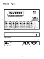
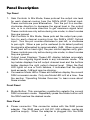
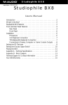
G
U
A
R
A
N
T
E
E
D
F
O
R
L
I
F
E
1
MANUAL
SAM ™
24 BIT
S / P D I F / A D AT
MIXER & FORMAT
CONVERTER
Table of Contents
FCC Class B and CE Compliance . . . . . . . . . . . . . . . . . 2
Introduction . . . . . . . . . . . . . . . . . . . . . . . . . . . . . . . . . . 3
Features . . . . . . . . . . . . . . . . . . . . . . . . . . . . . . . . . . . . . 4
Panels - Fig. 1 . . . . . . . . . . . . . . . . . . . . . . . . . . . . . . . . 5
Panel Description . . . . . . . . . . . . . . . . . . . . . . . . . . . . . . 6
Top Panel . . . . . . . . . . . . . . . . . . . . . . . . . . . . . . . 6
Front & Rear Panel . . . . . . . . . . . . . . . . . . . . . . . . 6
Rear Panel . . . . . . . . . . . . . . . . . . . . . . . . . . . . . . . 6
Installation and Typical Setup . . . . . . . . . . . . . . . . . . . . 8
Typical Setup - Fig. 2 . . . . . . . . . . . . . . . . . . . . . . . 8
Typical Setup - Fig. 3 . . . . . . . . . . . . . . . . . . . . . . . 9
Operating Modes Overview
. . . . . . . . . . . . . . . . . . . . . 10
Specifications . . . . . . . . . . . . . . . . . . . . . . . . . . . . . . . . . 13
Troubleshooting . . . . . . . . . . . . . . . . . . . . . . . . . . . . . . . 14
Lifetime Limited Warranty . . . . . . . . . . . . . . . . . . . . . . . 15
FCC Class B and CE Compliance
WARNING: This equipment has been tested and found to comply
with the limits for a CLASS B digital device, pursuant to Part 15 of
the FCC Rules. These limits are designed to provide reasonable protection against harmful interference in a residential installation. This
equipment generates, uses and can radiate radio frequency energy
and, if not installed and used in accordance with the instructions
contained in this manual, may cause harmful interference to radio
and television communications. However, there is no guarantee that
interference will not occur in a particular installation.
If this equipment does cause harmful interference to radio or television reception, which can be determined by turning the equipment
off and on, the user is encouraged to try to correct the interference
by one or more of the following measures: 1) reorient or relocate the
receiving antenna; 2) increase the separation between the equipment and the receiver; 3) connect the equipment into an outlet on a
circuit different from that of the receiver; 4) consult the dealer or an
experienced audio television technician.
NOTE: Connecting this device to peripheral devices that do not
comply with CLASS B requirements or using an unshielded peripheral data cable could also result in harmful interference to radio or
television reception.
The user is cautioned that any changes or modifications not
expressly approved by the party responsible for compliance could
void the user’s authority to operate this equipment.
To ensure that the use of this product does not contribute to interference, it is necessary to use shielded I/O cables.
This product also complies with European CE requirements.
2
Introduction
Thank you for choosing the SAM 24-Bit ADAT / S/PDIF Mixer &
Format Converter. The SAM has six different selectable modes with
which to convert between ADAT Optical Digital Interface and S/PDIF
interface signals. SAM can convert in either direction. In order to
deliver the highest conversion quality, the SAM features “lossless”
24-bit transfers in direct modes, and in mixer mode provides highresolution 56-bit internal processing for remarkable transparency.
The SAM is therefore the perfect studio “go between” for transferring audio tracks to and from ADAT machines, computer digital
audio cards, DAT machines, Digital Audio Workstations, external
converters or any other devices equipped with S/PDIF and/or ADAT
Optical digital interface technology. Keep all of your transfers,
mixes, and sub-mixes in the digital domain with the latest in ADAT
Optical Digital Interface & S/PDIF conversion technology - the SAM.
This manual assumes you have a basic understanding of the ADAT
Optical Digital Interface and S/PDIF interfaces. If after reading the
manual you need additional technical support, or if you have comments or suggestions, we invite you to contact us directly by any
one of the following methods:
MIDIMAN U.S.
45 East Saint Joseph Street ● Arcadia, CA 91006-2861 ● U.S.A.
Sales Information: 626.445.2842
Sales Information (email): [email protected]
International Sales (email): [email protected]
Tech Support: 626.445.8495
Tech Support (email): [email protected]
Fax: 626.445.7564
Internet Home Page: http://www.midiman.net
MIDIMAN U.K.
Hubberts Bridge House ● Hubberts Bridge ● Boston, Lincs. ● PE20 3QU England
Sales Information: 01205 290680
Sales Information (email): [email protected]
Technical Support: 01309 671301
Technical Support (email): [email protected]
Fax: 01205 290671
MIDIMAN Deutschland (Germany)
Kuhallmand 34 ● D-74613 Ohringen ● Germany
Sales Information: 07941-98-7000
Sales Information (email): [email protected]
Technical Support: 07941-98-70030
Technical Support (email): [email protected]
Fax: 07941-98-70070
Internet Home Page: http://www.midiman.de
* ADAT is a registered trademark of Alesis Corporation.
3
What's in the Box?
◆
◆
◆
◆
◆
◆
◆
◆
This Instruction Manual
SAM
Power Adapter
Midiman Warranty Registration Card
IMPORTANT: Please take the time to fill out the included Warranty
Registration Card and mail or fax it to us. Registering your SAM will
help us to give you the best possible service and support.
Features
◆ Converts between ADAT Optical Digital Interface and S/PDIF
digital interface signals, in either direction.
◆ In Mix Mode, SAM is an 8-input (ADAT Optical), 2-output
◆
◆
◆
◆
◆
◆
◆
◆
◆
(S/PDIF) digital mixer with independent gain and pan controls
per each ADAT input channel.
In direct ADAT-to-S/PDIF modes, SAM is a transparent format
converter, routing selectable 2-track pairs from the SAM’s ADAT
input to the S/PDIF output.
In S/PDIF-to-ADAT modes, SAM is a transparent format converter that routes S/PDIF left to ADAT channels 1, 3, 5 and 7; and
routes S/PDIF right to ADAT channels 2, 4, 6 and 8.
”Lossless” 24-bit conversion in all direct modes.
24-bit Mix Mode with 56-bit internal processing.
Signal level and clipping indicators for left and right output channels.
Supports all sample rates from 39 kHz to 51 kHz.
Internal high-performance DSP.
Rugged, all-steel construction.
Compact desktop size: 7” x 4.5” x 1”.
4
Panels - Fig. 1
sam
®
TM
24 Bit SPDIF / ADAT MIXER
& FORMAT CONVERTER
L
2.
-20 -12 -9
-6
-3
-1/Clip
R
1
2
3
4
5
6
7
8
SPDIF
3.
7&8
5&6
PAN
PAN
PAN
PAN
PAN
PAN
PAN
PAN
3&4
1&2
Mix
GAIN
GAIN
GAIN
GAIN
GAIN
GAIN
GAIN
GAIN
MODE
Top Panel
4.
1.
Front Panel
5.
9.
6.
10.
9 VDC
In
Rear Panel
7.
5
adat
In
Out
8.
spdif
Out
Panel Description
Top Panel
1. Gain Controls: In Mix Mode, these pots set the output mix level
for each channel coming from the SAM’s ADAT Optical input.
These controls are pure attenuators. Turn the pot in a counterclockwise direction to decrease the signal level in the output
mix, or in a clockwise direction to get maximum signal level.
These controls are only active during mix mode; in direct modes
they are ignored.
2. Pan Controls: In Mix Mode, these pots set the output pan position for each channel coming from the SAM’s ADAT Optical
input. Turn the pot counter-clockwise to pan left, or clockwise
to pan right. When a pan pot is centered (in its detent position)
the signal is attenuated by approximately -3dB. When a pan pot
is set hard left or hard right, the pan control applies unity gain.
These controls are only active during mix mode; in direct modes
they are ignored.
3. Output Level Displays: These LED display ladders accurately
depict the outgoing signal levels in any conversion mode. The
top ladder displays the left output channel level and the bottom
ladder displays the right output channel level. When the Red
LED lights on one or both ladders, it indicates that the signal
level exceeds -1dB and may be clipping.
4. Conversion Mode LEDs: These six indicators display the current
SAM conversion mode. Only one Mode LED is lit at a time. See
the section 'Operating Modes Overview' to learn more about
these modes.
Front Panel
5. Mode Button: This momentary pushbutton selects the current
SAM conversion mode. Repeatedly press the Mode button until
the SAM reaches the desired mode.
Rear Panel
6. Power connector: This connector mates with the SAM power
adapter. The SAM uses a 9 Volt DC, 500 milliamp, center-pin
positive supply. When the adapter is plugged into the SAM
6
power connector SAM is automatically powered up.
7. ADAT In: This connector mates with an optical cable carrying an
ADAT Optical Digital Interface signal into the SAM. This highspeed optical signal is capable of transferring 8 channels of 24bit audio data simultaneously.
8. ADAT Out: This connector mates with an optical cable carrying
an ADAT Optical Digital Interface signal out of the SAM. This
high-speed optical signal is capable of transferring 8 channels
of 24-bit audio data simultaneously. The sample rate of the
ADAT Out data will be synchronized with the incoming S/PDIF In
data.
9. S/PDIF In: This connector mates with a (male) RCA coaxial cable
carrying S/PDIF data into the SAM. This signal is capable of
transferring two-channel "left/right stereo" data of up to 24 bits.
10. S/PDIF Out: This connector mates with a (male) RCA coaxial
cable carrying S/PDIF data out of the SAM. This signal is capable of transferring two-channel "left/right stereo" data of up to
24 bits. The sample rate of the S/PDIF Out data will be synchronized with the incoming ADAT In data.
7
Installation and Typical Setup
Your SAM box should contain this user manual, a power adapter,
Midiman warranty card and the SAM unit itself. Remove the SAM
and power adapter from the box. Verify that the SAM and any other
devices you plan to connect to it are turned off (devices with ADAT
Optical connections may remain on but their volumes should be
turned down or off). Now, connect your S/PDIF and ADAT Optical
cables to the SAM. Plug one end of the power adapter into the
SAM's power jack and plug the other end of the power adapter into
a live wall socket or power strip -- this will power up the SAM unit.
With all volume controls of non-SAM equipment turned down or off,
power up each of these devices.
Note: The SAM has no Power On/Off switch. However, the SAM
may be safely left on continuously, 24 hours a day. After hours of
operation, it is normal for the SAM metal chassis to become slightly
warm to touch.
A typical configuration in which a SAM would be used includes a
SAM, an ADAT, a computer-based S/PDIF digital I/O card or DAT
recorder with S/PDIF I/O and an amplifier/sound system for monitoring purposes. Such an example configuration could be setup as follows: 1.) the Optical Out of the ADAT connects to the Optical In of
the SAM, 2.) the S/PDIF Out of the SAM connects to the S/PDIF In
of the digital audio card and DAT, 3.) an analog audio out from the
computer or DAT may connect to an amplifier/sound system.
Typical Setup - Fig. 2
ADAT
Computer
sam
or
DAT
8
Sound
System
Additionally, the signal path might be reversed in the same basic
configuration and both setups may exist simultaneously. In this
case: 1.) the S/PDIF Out of the digital audio card or DAT connects to
the S/PDIF In of the SAM; 2.) the Optical Out of the SAM connects
to the Optical In of the ADAT.
Typical Setup - Fig. 3
Sound
System
ADAT
Computer
sam
DAT
9
Operating Modes Overview
The SAM has six different operational modes which are selectable
via the Mode button. Five of these modes translate ADAT Optical
signals to the S/PDIF format and the sixth mode translates S/PDIF
signals to the ADAT Optical format.
Mix Mode:
When SAM is first turned on it will be in Mix mode, one of the
ADAT-to-S/PDIF modes. Here, all eight ADAT channels may be
combined into a stereo S/PDIF signal using the built-in mixer. Note
that the SAM mixer will generate a 24-bit output even if the ADAT
Optical signal originates from a source with less than 24-bit resolution.
Other ADAT-to-S/PDIF modes:
There are four other modes that translate ADAT-to-S/PDIF. They are
labeled “1&2”, “3&4”, “5&6”, and “7&8.” These modes resemble the
presets of other format translators, allowing you to make an exact
bit-for-bit copy of two adjacent ADAT channels to S/PDIF. In these
modes SAM will ignore its Gain and Pan pots – they are disabled.
S/PDIF Mode:
This is the S/PDIF-to-ADAT mode. SAM will distribute the incoming
stereo S/PDIF signal to the eight outgoing ADAT channels as follows:
S/PDIF left = ADAT channels 1, 3, 5, 7
S/PDIF right = ADAT channels 2, 4, 6, 8
Again, SAM will make an exact bit-for-bit copy of each input channel, and will ignore its Gain and Pan pots.
In any mode, only two digital audio connections need to be made to
the SAM in order for the SAM to operate properly – one ADAT optical and S/PDIF coax. In all ADAT-to-S/PDIF modes, SAM accepts
ADAT Optical Digital Interface audio data at the ADAT In jack, and
outputs S/PDIF coaxial audio data from the S/PDIF Out jack. In the
S/PDIF-to-ADAT mode, SAM accepts S/PDIF coaxial audio data
from the S/PDIF In jack, and outputs ADAT Optical Digital Interface
audio data from the ADAT Out jack. In all modes, if there is no valid
10
input signal present the mode LED will flicker very rapidly. It will
stop flickering and remain lit if a valid signal is present.
Note: The ADAT In and ADAT Out jacks expect ADAT-compatible
multi-channel signals (ADAT Optical Data Interface format), as
opposed to optical S/PDIF standard. SAM does not support conversion to and from optical S/PDIF formats, although there are other
products on the market that will convert between optical (Toslink)
and coax S/PDIF formats (the Midiman Co2 product for example).
Note: For best results, use a good-quality S/PDIF cable. The cable
should be coaxial with 75-ohm impedance. A good quality video
dubbing cable (for example) has these characteristics, as do more
expensive professional-quality S/PDIF cables.
In any of the modes, the output sample rate will always be synchronized with the input sample rate. In other words, when using ADATto-S/PDIF modes, the sample rate will be determined by the ADAT
optical stream; when using S/PDIF-to-ADAT mode, the sample rate
will be determined by the S/PDIF optical stream.
The LED output level displays are peak meters that show real-time
output signal levels in all modes. Output level in all direct modes
will precisely match that of the source level. Output level in mix
mode is controlled by the sum of the individual rotary Gain controls.
Digital clipping is occuring when the red “-1/Clip” LED is lit.
Note: Excessive clipping (causing the red “-1/Clip” LED to light
often or to stay lit) may cause extreme distortion and should be
avoided. An occasional CLIP reading is sometimes OK -- it's best
to let your ears be the judge! Generally speaking, the maximum
level before clipping (the yellow “-3” LED lighting occasionally or frequently) is the best level to maintain.
The Mix mode is a special mode in which the SAM gain and pan
pots are active. Each incoming ADAT channel may be independently attenuated and panned within a stereo output signal. Each Gain
control may be set anywhere from infinite attentuation (turned all the
way counter-clockwise) to 0 dB or “unity gain” (turned all the way
clockwise). This level is also influenced by the position of the Pan
control. In the center detent position, a Pan control attenuates the
signal by 3dB. This practice of slight attenuation in the center posi11
tion is common on many mixing consoles, compensating for the
increased presence that a signal will have when positioned in the
center of the stereo image as opposed to hard left or hard right.
When a Pan control is set hard left (fully counter-clockwise) or hard
right (fully clockwise), the signal is not attenuated.
Note: In Mix mode, true unity gain is only achieved when a channel’s
Gain control is turned all the way up (fully clockwise) and its Pan
control is set to either hard left (fully counter-clockwise) or hard right
(fully clockwise).
12
Specifications
Audio Inputs:
Audio Outputs:
External Data Width:
Internal DSP Data Width:
Gain Control Range:
Gain Control Resolution:
Pan Control Range:
Pan Control Resolution:
Pan Control Gain:
Level Meters:
Power Supply:
ADAT Optical Data Interface (x1),
S/PDIF coaxial RCA (x1).
ADAT Optical Data Interface (x1),
S/PDIF coaxial RCA (x1).
24 bits.
56 bits.
-Infinity to 0dB, center (half-way)
setting is -12dB.
128 steps.
Left to right with center detent.
128 steps.
0dB (left), -3dB (center), 0dB (right).
6 levels (x2): -20dB,-12dB,-9dB,-6dB,
-3dB,-1dB/Clip.
External 9VDC adapter, center-pin
positive, 500mA.
13
Troubleshooting
Symptom:
Solution:
Symptom:
Solution:
Symptom:
Solution:
Symptom:
Solution 1:
Solution 2:
Symptom:
Solution:
When power is applied, no LED's are lit on the SAM
front panel.
Make sure the correct power adapter is properly
plugged into the unit and into a live wall source or
power strip.
When first turning the unit on, you sometimes hear
small bursts of noise or a "pop" sound if monitoring the
SAM.
This is normal as it takes a small amount of time for an
acceptable digital audio signal to be generated, and
external devices usually require a small amount of time
to lock onto a valid digital signal. Be sure to turn down
the volume on externally connected devices before
powering up the SAM.
Even though an audio signal is being input into the
SAM, the Output Level LED's appear dim or not at all.
Check your source signal levels and cables. Either the
source signal is too weak or there is no digital target
plugged into the SAM’s output.
The front panel Input Level CLIP LED is always lit (or
frequently lit).
Check your source signal levels and cables.
In Mix Mode, the sum of the Gain control levels may be
too high. Reduce the levels of the Gain Controls so
that the clipping level indicators rarely or never light.
The SAM does not appear to work with optical S/PDIF
connected to the ADAT In or ADAT Out jacks.
The SAM does not support optical S/PDIF format. A
Midiman Co2 is recommended for S/PDIF optical-coax
conversion.
14
Lifetime Limited Warranty
MIDIMAN warrants that this product is free of defects in materials and
workmanship under normal use so long as the product is owned by the
original purchaser and that purchaser has registered his/her ownership of
the product by sending in the completed warranty card.
In the event that MIDIMAN receives written notice of defects in materials or
workmanship from such an original purchaser, MIDIMAN will either replace
the product, repair the product, or refund the purchase price at its option.
In the event any repair is required, shipment to and from MIDIMAN and a
nominal handling charge shall be born by the purchaser. In the event that
repair is required, a Return Authorization number must be obtained from
MIDIMAN. After this number is obtained, the unit should be shipped back
to MIDIMAN in a protective package with a description of the problem and
the Return Authorization clearly written on the package.
In the event that MIDIMAN determines that the product requires repair
because of user misuse or regular wear, it will assess a fair repair or
replacement fee. The customer will have the option to pay this fee and
have the unit repaired and returned, or not pay this fee and have the unit
returned unrepaired.
The remedy for breach of this limited warranty shall not include any other
damages. MIDIMAN will not be liable for consequential, special, indirect, or
similar damages or claims including loss of profit or any other commercial,
damage, even if its agents have been advised of the possibility of such
damages, and in no event will MIDIMAN’s liability for any damages to the
purchaser or any other person exceed the price paid for the product,
regardless of any form of the claim. MIDIMAN specifically disclaims all
other warranties, expressed or implied. Specifically, MIDIMAN makes no
warranty that the product is fit for any particular purpose.
This warranty shall be construed, interpreted, and governed by the laws of
the state of California. If any provision of this warranty is found void, invalid
or unenforceable, it will not affect the validity of the balance of the warranty, which shall remain valid and enforceable according to its terms. In the
event any remedy hereunder is determined to have failed of its essential
purpose, all limitations of liability and exclusion of damages set forth herein
shall remain in full force and
15
If you have any questions, comments or suggestions about this product or any
MIDIMAN product, we invite you to contact us directly at:
MIDIMAN U.S.
45 East Saint Joseph Street
Arcadia, CA 91006-2861 U.S.A.
Sales Information:
626.445.2842
Sales Information (email):
[email protected]
International Sales (email):
[email protected]
Tech Support:
626.445.8495
Tech Support (email):
[email protected]
Fax:
626.445.7564
Internet Home Page:
http://www.midiman.net
MIDIMAN U.K.
Hubberts Bridge House
Hubberts Bridge
Boston, Lincs.
PE20 3QU England
Sales Information:
Sales Information (email):
Technical Support:
Technical Support (email):
Fax:
01205 290680
[email protected]
01309 671301
[email protected]
01205 290671
MIDIMAN Deutschland (Germany)
Kuhallmand 34
D-74613 Ohringen Germany
Sales Information:
Sales Information (email):
Technical Support:
Technical Support (email):
Fax:
Internet Home Page:
07941-98-7000
[email protected]
07941-98-70030
[email protected]
07941-98-70070
http://www.midiman.de
1