1
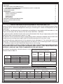
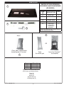
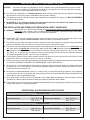
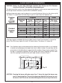
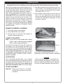
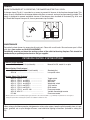
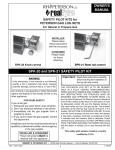
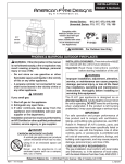
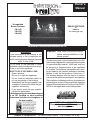
Owner’s
Manual
Unregulated
Burner Systems:
DESIGN CERTIFIED
to
RGA2-72
for natural gas only
PB-18(P)
PB-24(P)
PB-30(P)
PB SERIES GLASS/PAN BURNER SETS
WARNING
If the information in this manual is not
followed exactly, a fire or explosion can
result, causing property damage, personal
injury, or loss of life.
Do not store or use gasoline or other
flammable vapors and liquids in the vicinity
of this or any other appliance.
WHAT TO DO IF YOU SMELL GAS:
• Open a window.
• Do not try to light any appliance.
• Do not touch any electrical switch; do
not use any phone in the building.
• Immediately call the gas supplier from
a neighbor’s phone and follow the gas
supplier’s instructions.
• If you cannot reach the gas supplier,
call the fire department.
Installation and service must be performed
by an NFI Certified or other qualified
professional installer, service agency, or
the gas supplier.
Important: Read these instructions carefully
before starting installation of the
burner system.
This burner system is to be installed only in a solidfuel-burning fireplace with a working flue constructed
of noncombustible material. Solid fuels shall not
be burned in a fireplace where a gas appliance
is installed. The minimum permanent vent opening provided by the fireplace chimney or chimney
damper to vent the flue products is listed on p. 2.
The chimney damper must be fixed in a manner
to maintain the minimum permanent vent opening.
The installation, including provisions for combustion
and ventilation air, must conform with the American
National Standard National Fuel Gas Code Z223.1/
NFPA 54 and applicable local building codes.
INSTALLER & CONSUMER
These instructions MUST be retained
with this appliance.
ROBERT H. PETERSON CO. • 14724 East Proctor Avenue • City of Industry, CA 91746
REV 3 - 0903201116
1
No. L-A2-22609
TABLE OF CONTENTS
IMPORTANT SAFETY INFORMATION
PARTS LIST
IMPORTANT SAFETY INFORMATION (Cont.)
PRE-INSTALLATION AND FIREPLACE PREPARATION SAFETY GUIDELINES
GLASS QUANTITY DETERMINATION
LOG SET NOTES PAGE
INSTALLATION
BURNER PLACEMENT & ASSEMBLY
CONNECT GAS SUPPLY
GLASS PLACEMENT
DAMPER STOP
MAINTENANCE
PETERSON CONTROL SYSTEM OPTIONS
MANUAL LIGHTING INSTRUCTIONS
WARRANTY
2
3
4
4
5
6
7
7
7
7
8
8
8
9
10
IMPORTANT SAFETY INFORMATION
CHECK TO BE SURE VENTED GAS BURNER IS FOR PROPER GAS TYPE
Peterson PB Series burner sets are designed for use with natural gas, unless clearly labeled for propane. Never
use propane gas in a burner set designed for natural gas, or natural gas in a burner set designed for use with
propane gas.
The installation, including provisions for combustion and ventilation air, must conform with local codes or, in the
absence of local codes, with the National Fuel Gas Code, ANSI Z223. 1 (NFPA54).
The appliance and its individual shutoff valve must be disconnected from the gas-supply piping system when
testing the system at test pressures in excess of ½ psig.
The appliance must be isolated from the gas-supply piping system by closing its individual manual shutoff valve
during any pressure testing of gas-supply system at test pressures equal to or less than ½ psig.
The minimum inlet gas-supply pressure for the purpose of input adjustment is 5" for natural gas and 10" for
propane gas. The maximum inlet gas-supply pressure for this burner is 10.5" for natural gas and 13" for propane
gas. A fireplace screen must be in place when the pan burner set is burning.
WHEN GLASS FIREPLACE ENCLOSURES (DOORS) ARE USED, OPERATE THE GAS BURNER SET WITH
THE GLASS DOORS FULLY OPEN. KEEP APPLIANCE AREA CLEAR & FREE FROM COMBUSTIBLE
MATERIALS, GASOLINE, AND OTHER FLAMMABLE VAPORS AND LIQUIDS.
The minimum size fireplace in which the burner is to be
installed is listed in Table 2-2.
Burner
Size
18"
24"
30"
Unregulated
Natural
Propane
75,000 BTU
60,000 BTU
90,000 BTU
75,000 BTU
90,000 BTU
80,000 BTU
The minimum-size fireplace in which the burner is to
be installed is listed in the table below:
Burner
Depth
Height
Front
Opening
Width*
18"
24"
30"
16"
16"
16"
16"
16"
16"
22"
28"
34"
*Add 4" to the minimum front opening width if the burner is to be
installed with a pilot kit. Double this measurement to center burner.
Table 2-1
Table 2-2
Minimum Free Opening Area of Chimney Damper for Venting
For Factory-Built Fireplaces
Burner Sizes
For Masonry-Built Fireplaces
Burner Sizes
Chimney Height
18"
24"
30"
18"
24"
30"
15'
46 sq. in.
56 sq. in.
69 sq. in.
50 sq. in.
60 sq. in.
73 sq. in.
20'
42 sq. in.
50 sq. in.
61 sq. in.
46 sq. in.
54 sq. in.
65 sq. in.
30'
37 sq. in.
45 sq. in.
55 sq. in.
41 sq. in.
49 sq. in.
59 sq. in.
Note: The minimum chimney height from hearth to top of chimney is 15'.
Table 2-3
REV 3 - 0903201116
2
No. L-A2-22609
PARTS LIST
PARTS LIST FOR PETERSON
PB SERIES GLASS PAN BURNER
(PB SERIES)
1
ITEM
NO.
1.
2.
DESCRIPTION
Burner pan
1
CK-5 connector kit
1
Damper clamp
1
Glass *
1
Sand (nat.)
or Lava-Fyre
GranulesTM
(propane) *
1
3.
4.
5.
2
QTY.
3
* Glass kits (which include sand/granules) are
sold and packed separately.
5
Glass
OR
(Clear, black, sapphire blue,
emerald green, or bronze)
Sand
(for natural gas)
4
Burner
18"
24"
30"
Lava-Fyre GranulesTM
(for propane)
Glass kit
GLF-18-(P)x
GLF-24-(P)x
GLF-30-(P)x
Replace "x" in model number with the
glass code in parentheses below:
Black (B)
Clear (C)
Bronze (Z)
Sapphire blue (S)
Emerald green (E)
REV 3 - 0903201116
3
No. L-A2-22609
IMPORTANT SAFETY INFORMATION (Cont.)
CAUTION:
Installation and repair must be done by an NFI Certified or other qualified professional installer. Installer:
Carefully read these instructions before installing this gas appliance. Be sure you understand all safety
precautions and warnings contained in this manual.
A. This appliance is designed as an attended appliance. Adults must be present when this gas appliance is operating.
Do not leave this unit burning when unattended or while anyone is sleeping.
B. This appliance is only for use with the type of gas indicated on the rating plate. This appliance is NOT CONVERTIBLE
for use with other gasses.
C. BE CAREFUL: If not installed, serviced, and used correctly per these instructions, this product can cause
serious personal injury, property damage, or loss of life.
PRE-INSTALLATION AND FIREPLACE PREPARATION SAFETY GUIDELINES
Before installing in a solid-fuel-burning fireplace, the chimney flue, damper, and firebox must be thoroughly
D. WARNING: CLEANED of soot, creosote, ashes, and loose paint and inspected by a qualified chimney cleaner. Some
older fireplaces may need repair prior to installing this appliance.
E. CHECK GAS TYPE (natural or propane): The gas supply must be the same as stated on the burner system rating
plate. If gas supply is different, DO NOT INSTALL. Contact the dealer for immediate assistance.
F. Any outside air ducts and/or ash dumps located on the floor or walls of the fireplace must be permanently sealed shut
before the installation. Use a heat-resistant sealant. Do not seal the chimney flue damper.
G. The minimum inlet gas-supply pressure for purposes of input adjustment is 5" water column (w.c.) on natural gas and
10" water column on propane gas. Insufficient gas pressure will affect proper operation of the pilot. Do not install this
gas appliance if minimum pressure is not available. The maximum inlet gas-supply pressure is 10.5" w.c. on natural
gas and 13" w.c. on propane gas. The propane source must be regulated. (Do not connect this appliance directly to
an unregulated propane gas tank - this can cause an explosion.)
H. The gas piping system must be sized to provide minimum inlet pressure at the maximum flow rate (BTU/hr). Undue
pressure loss will occur if the pipe is too small, or the run is too long.
I.
The minimum clearance from the fireplace opening to combustible materials on side walls and ceiling must be maintained
as outlined in MINIMUM CLEARANCE TO COMBUSTIBLES - WALLS AND CEILING.
J. At least 10"-12" of noncombustible or heat-resistant material is required above the fireplace. A fireplace hood will
be required to act as a heat deflector in protecting combustible fireplace surrounds (facing and/or mantel) if certain
minimum clearances cannot be met.
K. Be certain that combustible flooring material (i.e., carpet, tile, etc.) is not too close to this gas appliance. If this appliance
is at floor level or less than 6" above the floor, there must be at least 12" of noncombustible material between the base
of the fireplace and any combustible flooring.
L. Input ratings shown in BTU per hour are for elevations up to 2,000 ft. Refer to the National Fuel Gas Code, or contact
the Robert H. Peterson Company before installing this product at elevations above 2,000 ft.
M. The gas appliance and its main gas valve must be disconnected from the gas-supply piping system during any pressure
testing of that system, as required by NFPA 54.
OPERATIONAL GAS PRESSURE SPECIFICATIONS
NATURAL GAS
MANUAL PRESSURE
Gas inlet pressure:
MILLIVOLT PRESSURE
Max. 10.5" w.c. Inlet pressure reading:
Max. 10.5" w.c.
Min. 5" w.c.
Min. 5" w.c.
PROPANE GAS
MANUAL PRESSURE
Gas inlet pressure:
MILLIVOLT PRESSURE
Max. 13" w.c.
Inlet pressure reading:
Min. 10" w.c.
REV 3 - 0903201116
Max. 13" w.c.
Min. 10" w.c.
4
No. L-A2-22609
GLASS QUANTITY DETERMINATION
CAUTION: Sand is for use with natural-gas systems only. Always use R.H. Peterson
Lava-Fyre Granules™ for systems using propane gas.
The glass and either sand or lava that come with the burner system are pre-measured and must
be used per these instructions (see GLASS PLACEMENT section).
Additional decorative glass may be placed on or around the burner (but not on the valve or pilot).
Use Table 5-1 to determine how many bags of glass to order based on fireplace size.
Fireplace
glass
coverage
Table 5-1
Standard
Fireplace
Sizes
Fireplace
Opening
size
Center
width (in.)
Glass
Front to
Area
back depth
(sq. in.)
(in.)
28"
25
16
36"
32" see-thru
42"
30
31
36
23
23
30
50"
46
33
400
540
690
713
828
1085
1334
10 lb. bags*
for 2" depth
5
7
9
10
11
14
18
*One bag of glass is included with a bag of either sand or Lava-Fyre Granules™ to cover the
burner. One 10-lb. bag of glass fills about 155 cubic inches. The burner is 2 inches tall.
Note: Your fireplace area can be determined by measuring the center width of your fireplace
in inches and multiplying by the depth from front to back in inches. You can then use the
area column in the table above to approximate the number of bags of glass needed. Seethrough or rectangular fireplaces will have greater area than a fireplace with the same
size front opening in which the side walls taper inward as shown in Fig 5-1.
Center
Width
DEPTH
Depth
H
eight
HEIGHT
Fig. 5-1
CAUTION: Covering the burner with glass more than 1" above the top of the burner may
result in unsafe ignition. Use only the glass provided with the burner to cover
the burner itself. Do not use extra decorative glass directly on top of the burner.
5
NOTES PAGE
Please use this page to record any information about your burner system that you may want to have at hand.
6
INSTALLATION
This burner system must be installed by an NFI Certified or other qualified professional installer. Instructions must
be followed carefully when installing to ensure proper performance and full benefit from the burner system.
Real-Fyre® gas burner sets must be installed only in a
solid-fuel-burning fireplace with flue, and constructed
of noncombustible material. Solid fuels shall not be
burned where a decorative appliance is installed.
1. Pour either sand (for natural-gas burners) or LavaFyre GranulesTM (for propane-gas burners) into
bottom of burner pan just below level of center
flame baffle (Fig. 7-1 & 7-2).
Open damper fully and be sure damper clamp is in
place (see DAMPER STOP installation instructions).
Check PARTS LIST to be sure all parts are included.
Inspect to be sure the burner has air mixer or fuel
injection installed. For safe operation and proper
performance, use only Robert H. Peterson parts and
accessories. Gas-supply pipe must be ½" minimum
I.D. or larger (¾") if gas line is longer than 20'. REFER
TO PARTS LIST WHEN FOLLOWING THESE
INSTRUCTIONS.
2. Pour contents of glass bag to top of the pan rim
(Fig. 7-1 & 7-2). If safety pilot is used, make sure
to place the heatshield over the valve assembly
and cover the pilot before pouring glass to avoid
pouring it on the pilot.
BURNER PLACEMENT & ASSEMBLY
1. Turn off gas supply to the fireplace.
2. Clean fireplace floor of any ashes.
Fig. 7-1
3. Place the pan as far back in the fireplace as
possible, centered right to left.
CONNECT GAS SUPPLY
Note: If your unit is to be installed with a safety
pilot kit, refer to the instructions supplied
with it for gas supply connection.
Using the CK-5 connector kit (Item #2), connect the
gas supply to the valve assembly inlet. Make sure
to attach the flare fitting between the corrugated
hose and gas-supply line. DO NOT KINK TUBING.
PIPE COMPOUND RESISTANT TO THE ACTION
OF PROPANE GASSES MUST BE USED ON ALL
THREADED MALE CONNECTIONS, EXCEPT
BRASS TO BRASS.
Fig. 7-2
Sand used for natural gas burner (Fig. 7-1); for
propane gas, use Lava-Fyre GranulesTM under glass.
LEAK TESTING
WARNING
Failure to position the parts in accordance with
these instructions and diagrams, or failure to use
only parts specifically approved with this appliance,
can result in property damage or personal injury.
Use a long-necked butane lighter, or lay a lighted
match next to the burner pipe, and carefully turn on the
gas supply until the burner ignites. Test for leaks at all
connections with a soapy water solution. Never use an
open flame to check for leaks. Turn off gas supply.
GLASS PLACEMENT
Important: Make sure the burner is off before
pouring glass and sand or Lava-Fyre
GranulesTM.
7
INSTALLATION (Cont.)
DAMPER
WHEN THE BURNER SET IS OPERATING, THE DAMPER MUST BE FULLY OPEN.
A damper clamp (Fig. 8-1) is provided as a means to prevent full closure of the fireplace damper blade. This
clamp is easily attached to most damper blades with pliers or wrench, and must be permanently installed. The
clamp is designed to prevent accidental closure of the damper when installed as illustrated (Fig. 8-2a and
b). Should the damper clamp not fit, have a permanent stop installed.
Open
Fig. 8-1
Fig. 8-2a
Closed
Fig. 8-2b
MAINTENANCE
Periodically check burner for excessive dirt and soot. Clean with a soft brush. Be sure burner pan is filled
with glass (see section on GLASS PLACEMENT).
Periodically examine and clean the venting system of the solid-fuel-burning fireplace. This should be
conducted by a qualified professional or the gas supplier.
PETERSON CONTROL SYSTEM OPTIONS
Manual On/Off Systems
AV-17 (knob) or AV-18 (rod handle) ................
Manual On/Off, match lit, no pilot
Manual Safety Pilot Systems*
SPK-20 (knob) or SPK-21 (rod handle) ..........
SPK-26 ...........................................................
Standard pilot
Low-profile valve
Remote Safety Pilot Systems*
APK-11, EPK-1 ............................................
APK-11, EPK-1 and WS-1 ........................
APK-11, EPK-1 and WS-2 .........................
APK-11, EPK-1 and WCS-1 .....................
APK-11, EPK-1 and RRF-1 .......................
APK-11, EPK-1 and RUS-1 .......................
APK-11, EPK-1 and PC-100 .....................
APK-15, APK-17...............................................
PC-106
..........................
Toggle switch
Wall switch
Wall timer
Wood chip switch
110V remote
RUS remote
Pine cone remote
Variable flame-height remote
Pine cone remote
* When systems are to be used with propane gas, add a “P” to the control model No. (e.g., APK11P). Propane burner sets require a
safety pilot system. Not all safety pilot systems are available for all burner sizes.
When using a pilot/thermocouple, pilot/generator safety valve system, keep the pilot/assembly clear of sand,
glass, granules, etc. or pilot outage will occur, read and follow lighting instructions (included in safety pilot
kit).
8
MANUAL LIGHTING INSTRUCTIONS
FOR YOUR SAFETY, READ BEFORE LIGHTING
WARNING: If you do not follow these instructions exactly, a fire or explosion can result,
causing property damage, personal injury, or loss of life.
Do not use this appliance if any part has been underwater. Immediately call for a qualified professional
service technician to inspect the appliance and to replace any part of the control system and any
gas control that has been underwater.
BEFORE LIGHTING, smell all around the burner area for gas. Be sure to smell next to the floor as some
gas is heavier than air and will settle on the floor. IF YOU SMELL GAS, FOLLOW THE INSTRUCTIONS
ON P. 1.
Use only your hand to push in or turn the gas control knob. Never use tools. If the knob will not push in
or turn by hand, don't try to repair it. Call a qualified professional service technician. Force or attempted
repair can result in fire or explosion.
LIGHTING THE BURNER
4. Wait approximately five (5) minutes to clear out
any gas, and repeat steps 1-3 above. Smell for
gas, including near the floor. If you smell gas,
stop, and follow the instructions on p. 1. If you
don’t smell gas, go on to the next step.
If the Real-Fyre® glass burner set is operated
by the fireplace valve (natural only):
1. Lay a lighted long-stem match on the surface
of the glass near the gas inlet (do not hold
the match in your hand), or use a lighted
long-necked butane lighter.
5. If the burner fails to light again, turn off the gas
at the source and contact the dealer or gas
supplier.
2. Turn on the gas at the source.
6. To extinguish the Real-Fyre® glass/pan burner,
simply turn the valve to the OFF position. Be
sure the valve is turned completely off to avoid
any gas leakage.
3. If the burner does not light before the match
goes out, immediately turn off the gas at the
source.
If your gas log set is operated by a Peterson manual safety pilot system (SPK Series) or a
Peterson remote safety pilot system (APK Series):
1. Carefully follow the lighting instructions supplied with your Peterson pilot system for the steps to
ignite the burner.
9
WARRANTY
PETERSON VENTED DECORATIVE GAS APPLIANCE
LIMITED WARRANTY
All Peterson burner assemblies are WARRANTED for TEN (10) YEARS.
All Peterson glass is WARRANTED for TEN (10) YEARS.
SPK-26 controls are covered by a THREE (3) YEAR “All Parts” Warranty.
All other Peterson valves, pilots, and controls are covered by a ONE (1) YEAR Limited Warranty (excluding batteries).
PLEASE KEEP A COPY OF YOUR SALES SLIP FOR PROOF OF PURCHASE
This warranty applies to the original purchaser and to single family residential use only. It commences from date of purchase, and is valid only with
proof of purchase.
This warranty does not cover parts becoming defective through misuse, accidental damage, electrical damage, improper handling, storage, and/or
installation. Product must be installed (and gas must be connected) as specified in the instructions or operator’s manual, by a qualified professional
installer. Accessories, parts, valves, remotes, etc., when used must be Peterson Co. product.
This warranty does not apply to rust, corrosion, oxidation, or discoloration, unless the affected component becomes inoperable. It does not cover
labor or labor-related charges.
This warranty specifically excludes liability for indirect, incidental, or consequential damages. Some states do not allow the exclusion or limitation of
incidental or consequential damages, so the above exclusion may not apply to you. This warranty gives you specified legal rights, and you may have
other rights that may vary from state to state.
For additional information regarding this warranty, or to place a warranty claim, contact the R.H. Peterson dealer where the product was purchased.
TO REGISTER YOUR PRODUCT ONLINE GO TO: WWW.RHPETERSON.COM,
AND CLICK ON PRODUCT REGISTRATION. THANK YOU FOR YOUR PURCHASE.
Robert H. Peterson Co. • 14724 East Proctor Avenue • City of Industry, CA 91746
10