1
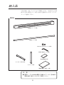
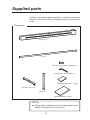
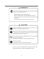
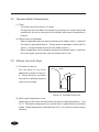
取扱説明書
User's Guide
乾燥装置100
(溶剤インク カラーインクジェットプリンタ IP-6900用)
Dryer 100
For solvent ink inkjet printer IP-6900
IP-270
ご使用の前に、この取扱説明書をよくお読みの
上、正しくお取り扱いください。
また、お読みになった後も、必要なときにすぐ見
られるよう、大切に保管してください。
Read this User's Guide to use the printer safely and
properly. Keep this manual in a place where you
can quickly access it at any time.
U00094500000
U00094500001
2005年
2005年
5月
6月
株式会社セイコーアイ・インフォテック 2005
無断転載を禁じます。
本書の内容は、断わりなく変更することがあります。
この装置は、情報処理装置等電波障害自主規制協議会(VCCI)の基準に基づくクラスA情報技術装
置で、商工業地域で使用されるべき装置です。この装置が、住宅地域またはその隣接した地域で
使用されると、ラジオ、テレビジョン受信機等に受信障害を引き起こすことがあります。
取扱説明書に従って正しく取り扱いをしてください。
「JISC61000-3-2適合品」
JISC61000-3-2適合品とは、日本工業規格「電磁両立性−第3-2部:限度値−高調波電
流発生限度値(1相当たりの入力電流が20A以下の機器)」に基づき、商用電力系統の高調波環
境目標レベルに適合して設計・製造した製品です。
Documents Number U00094500001
Fiirst Edition, May 2005
Second Edition, June 2005
Copyright © 2005 by Seiko I Infotech Inc.
All rights reserved
Seiko I Infotech Inc. reserves the right to make changes without notice to the specifications and
materials contained herein and shall not be responsible for any damages (including
consequential) caused by reliance on the materials presented, including but not limited to typographical, arithmetic, or listing errors.
This equipment has been tested and found to comply with the limits for a Class A digital device,
pursuant to Part 15 of the FCC Rules. These limits are designed to provide reasonable protection
against harmful interference when the equipment is operated in a commercial environment.
This equipment generates, uses, and can radiate radio frequency energy and, if not installed and
used in accordance with the instruction manual, may cause harmful interference to radio
communications. Operation of this equipment in a residential area is likely to cause harmful
interference in which case the user will be required to correct the interference at his own expense.
取扱説明書(日本語)
はじめに
このたびは、溶剤インク カラーインクジェットプリンタ IP-6900用
乾燥装置 100 (以後、乾燥装置と呼びます) をお買い上げいただき、
まことにありがとうございます。
乾燥装置は、プリンタから印刷出力されるメディア(インク)を効
率良く乾燥させるために、
プリンタの排紙面に設置してお使いいた
だきます。
溶剤インクインクジェットプリンタIP-6900の特長である高速印刷機
能を最大限にご活用いただけるよう用意しました。
特長
・ 高速印刷に応える高速乾燥
プリンタのメディア経路である排出口から巻き取り装置までの
間に温風をあててメディアを乾燥します。
・ 24 時間乾燥タイマー機能
タイマーにより、1 時間単位で、最大 24 時間までの乾燥時間設
定機能により、省エネ・高率的な乾燥が可能です。
注意:
インクそのものが完全に乾燥するには、
少し時間がかかり
ます。したがって、メディアにラミネート等の後加工が必
要な場合は、印刷直後の後加工は推奨できません。また、
メディアによっては充分に乾燥できない可能性がありま
す。その場合は、IP-6900 プリンタ本体の操作パネルから
スキャン待機時間を設定してお使いください。
i
乾燥装置は、IP-6900プリンタの排紙面に設置してご使用いただき
ますが、乾燥効率を最大限に引き出してお使いいただくために、
本書に記載の内容に従って正しくお使いください。
乾燥装置を安全に正しくお使いいただくために、ご使用になる前
に必ず下記をお読みください。
・組立説明書
・安全上の注意
・取り扱い上の注意
・マニュアル凡例(表記方法)
また、本書はお読みいただいた後も、必要なときにすぐ見られる
よう、大切に保管してください。
ii
納入品
下記の物が、揃っていることをご確認ください。欠品あるいは損
傷などがある場合には、お買い求めの店鋪あるいはサービスセン
ターにご連絡ください。
構成品
乾燥機ユニット<1個>
補強ステー<1個>
M5×12L六角穴付ボルト<16個>
M5用六角棒スパナ<1個>
組立説明書<1部>
キャスター付足<2個>
スタンド<2個>
取扱説明書(本書)<1部>
注 意
◆ 電源ケーブルは本体付属品に同梱されています。
各地域の
電源仕様に適合したものをご使用ください。
iii
安全上の注意
本書では、乾燥装置を安全に正しくお使いいただくため、または
機器の損傷を防ぐため、次の記号を使って注意を喚起しています。
これらの記号の意味は次のとおりです。内容をよく理解して、こ
れらの記号が表示されているところの記載事項については、必ず
お守りください。
警告
この表示の内容を無視して、誤った取り扱い
をすると、人が死亡または重傷を負う可能性
が想定される内容を示しています。
注意
この表示の内容を無視して、誤った取り扱い
をすると、人が傷害を負う可能性が想定され
る内容および物的損害のみの発生が想定され
る内容を示しています。
絵表示の例
記号は、注意(危険・警告を含む)を促す内容がある
ことを告げるものです。
左の表示例は安全上の「警告または注意事項」があるこ
とを表しています。
記号は、禁止の行為であることを告げるものです。
左の表示例は「分解禁止」を表しています。
記号は、行為を強制したり、指示する内容を告げる
ものです。
左の表示例は「電源プラグをコンセントから抜く」こと
を表しています。
iv
警告
表示された電源電圧以外の電圧で使用しないでください。また、
タコ足配線をしないでください。
火災や感電の原因になります。
乾燥装置をアース接続してください。
アース接続されないで使用し
ますと、万一漏電した場合は火災や感電の原因になります。
乾燥装置を分解したり、改造したりしないでください。
事故や故障の原因になります。
電源ケーブルを傷つけたり、破損したり、加工、加熱したりしないで
ください。また、破損した場合は新しいものに交換してください。
傷んだケーブルを使用し続けると火災や感電の原因になります。
湿気の異常に多い場所や水分のかかる可能性のある場所では、
絶
対に使用しないでください。
火災や感電や故障の原因になります。
乾燥装置の固定されているカバーは、外さないでください。内部
には電圧の高い部分、
高温の部分があり感電およびやけどの原因
となります。
乾燥装置の内部やすき間に、金属片を落としたり、水などの液体
をこぼさないでください。
火災や感電、故障の原因になります。
濡れた手で、電源ケーブルなどを接続したり、はずしたりしない
でください。
感電の原因になります。
雷が鳴り出したら、すぐに電源を切り電源プラグをコンセントか
ら抜いてください。
v
警告
次のような場合は、電源を切り、電源プラグをコンセントから
抜いてください。
異常状態のまま使用すると、事故や火災の原因になります。
◇ 手入れするとき
◇ 異臭がする、発熱した、煙が出た、または異常音が発生した
とき
◇ 乾燥装置の内部やすき間に、
金属片や水などの異物が入った
とき
◇ サービス拠点で対処する異常が発生したとき
注意
乾燥装置は重いので、落としたりしないように注意して、取り扱
いください。
足の上に落としたりすると、けがをする恐れがあります。
電源ケーブルを接続するときやはずすときは、
プラグ部またはコ
ネクタ部を持って行ってください。
コードを引っ張るとコードに傷が付き、火災や感電、故障の原因
になります。
ぐらついた台の上や傾いた場所など不安定な場所には置かないで
ください。落ちたり、倒れたりしてけがの原因になります。
ヒータ部は高温になります。触れて、やけどをしたりしないよう
に注意してください。
このほか、各項で示す警告、注意事項についてもお守りください。
vi
取り扱い上の注意
電源についての注意
1. 乾燥装置はコンセント近傍に設置し、そのコンセントへは容易
に手が届くようにしておいてください。
2. モータなどのノイズ発生源となる機器と同じ系路から、
電源を
とらないでください。
3. ご使用電源は、装置の仕様に合わせてお使いください。
4. 電源は単独で接続してください。
タコ足配線はしないでください。
乾燥装置本体についての注意
1. 乾燥装置の上に物を置いたり肘をついたりしないでください。
2. カバーの表面をベンジン、シンナーなどで拭かないでくださ
い。塗装がはげたり変質することがあります。
また、
カバーの汚れは柔らかい布などで軽くふき取ってくださ
い。汚れがひどいときは、水で薄めた中性洗剤に浸した布でよ
く絞ってから拭き取ってください。
3. 乾燥装置は、IP-6900 プリンタの乾燥装置として専用に用意さ
れています。他の装置や他の目的で、本装置を使用しないでく
ださい。
vii
マニュアル凡例(表記ルール)
本書で説明に使用する、マークなどの表記ルールを以下に示しま
す。
マーク表記について
●
警 告
◆ 安全上の注意における「警告」に相当する内容を説明して
います。
●
注 意
◆ 安全上の注意における「注意」に相当する内容を説明して
います。
●
注 意
◆ 乾燥装置の取り扱い上の注意事項を説明しています。
●
●
「参考」マークです。
参考 知っておくと便利なこと、操作などの補足事項を記載
しています。
⇒
「参照」マークです。
このマークの後に、参照項や参照ページを示していま
す。
viii
目 次
はじめに .............................................................................................. i
納入品 ................................................................................................. iii
安全上の注意 ...................................................................................... iv
取り扱い上の注意 .............................................................................. vii
マニュアル凡例(表記ルール) ....................................................... viii
1章
各部の名称と機能
1.1
1.2
各部の名称................................................................................ 1
操作パネルの名称とはたらき ................................................... 1
2章 設 置
2-1
2-2
2-3
3
設置空間 ................................................................................... 3
操作環境 ................................................................................... 4
電源コードの差し込みと乾燥装置の電源のON/OFF ................ 5
3章 乾燥装置の使い方
3-1
3-2
3-3
4章
5章
仕様
7
乾燥機の運転 ............................................................................ 7
運転モードの特性 ..................................................................... 8
上手な使いかた ........................................................................ 8
保守・クリーニング
4.1
4.2
1
11
保守 ........................................................................................ 11
外装のクリーニング ............................................................... 11
12
目次-1
図
図1-1 乾燥装置の外観と各部の名称 .................................................. 1
図1-2 操作パネルの外観と各部の名称 ............................................ 1
図2-1
図2-2
図2-3
図2-4
図2-5
図2-6
図2-7
目次-2
乾燥装置設置空間1 ................................................................ 3
乾燥装置設置空間2 ................................................................ 4
電源コード固定 ..................................................................... 5
プレーカスイッチON ............................................................ 6
温風の向き ............................................................................ 8
巻取装置を使用する場合 ..................................................... 10
巻取装置を使用しない場合 ................................................. 10
1章 各部の名称と機能
ここでは、乾燥装置の各部の名称と機能について説明します。
1.1 各部の名称
本体
温風吹出し口
操作パネル
ACインレット
ブレーカー
スタンド
背面図
正面図
キャスター
図1-1 乾燥装置の外観と各部の名称
1.2 操作パネルの名称とはたらき
7
8
1
9
10
2
3
4
5
6
図1-2 操作パネルの外観と各部の名称
1
No.
名称
機能
①
表示パネル
・ 表示パネルにはタイマーの残り時間が表示されます。
・ タイマー設定スイッチ⑤の▲▼を押すと、最小1時間
∼最大24時間まで表示します。
②
電源スイッチ
・ 装置の電源のON/OFFをします。
・ ヒータ動作中にOFFにしたときには、送風のみを3分
したのち、OFF状態となります。
③
ファンスイッチ
・ 送風動作を使用したいときに使用するスイッチです。
④
ヒータスイッチ
・ 温風動作を使用したいときに使用するスイッチです。
⑤
タイマー設定スイッチ
・ タイマーの時間を設定するときに使用するスイッチ
です。
・ 動作時間を最長24時間まで設定します。(設定時間
は表示パネルに表します。)
・ 電源投入時の初期値は10時間です。
⑥
風量切替スイッチ
・ 送風、温風の風量を切り替えるスイッチです。
・ 電源投入時には初期値はHです。
⑦
ファン運転ランプ
・ ファンが作動中に点灯します。
⑧
ヒータ通電ランプ
・ ヒータがONのときに点灯します。
⑨
風量表示ランプ
・ ファンの風量をH/M/Lの3段階で表示します。
⑩
ヒータ異常ランプ
・ ヒータが異常温度になったときに点灯します。
注意
◆ ヒータ異常ランプが点灯したときには、すぐにヒータスイッチで
温風動作を停止してください。ヒータをオフにした後、風量大(H)
で送風動作を 10 分間実施して、乾燥機内部を冷却してください。
冷却したのち、電源スイッチをオフ、ブレーカをオフにします。そ
の後、弊社のサービス拠点に連絡をしてください。
2
2章 設 置
ここでは、乾燥装置の設置のしかたについて説明します。
2-1 設置空間
乾燥装置の設置空間に図 2-1 と図 2-2 に示します。
(前)
IP-6900
400
12345678901234567890123456789012123456789012345
12345678901234567890123456789012123456789012345
12345678901234567890123456789012123456789012345
12345678901234567890123456789012123456789012345
12345678901234567890123456789012123456789012345
12345678901234567890123456789012123456789012345
12345678901234567890123456789012123456789012345
12345678901234567890123456789012123456789012345
12345678901234567890123456789012123456789012345
乾燥装置
12345678901234567890123456789012123456789012345
12345678901234567890123456789012123456789012345
12345678901234567890123456789012123456789012345
12345678901234567890123456789012123456789012345
12345678901234567890123456789012123456789012345
12345678901234567890123456789012123456789012345
12345678901234567890123456789012123456789012345
12345678901234567890123456789012123456789012345
400
2000
(後)
高さ: 1700
(単位: mm)
図 2-1 乾燥装置設置空間1
注意
◆ 設置後、キャスターのロックを ON にしてください。
3
50mm以上
300mm以上
吸
込
口
吹
出
し
口
壁など
乾燥するもの
図 2-2 乾燥装置設置空間2
注 意
◆ 乾燥機の吸込口と吹出口は、図2-2に示すように遮へい物
から離してください。
2-2 操作環境
乾燥装置は、下記の使用環境でお使いください。
項目
4
仕様
動作時温湿度範囲
温度: 15 ∼30 °C
湿度: 30 ∼70%RH (無結露)
停止時温湿度範囲
温度: 5∼35 °C
湿度: 10 ∼ 80%RH (無結露)
粉塵レベル
オフィス環境相当。
換気
必ず充分な換気をして使用。
電源
電源電圧
電源周波数
接地
: 230/200 VAC ± 10%
: 50/60 Hz ± 1%
: D 種(第3種)接地
2-3 電源コードの差し込みと乾燥装置の電源のON/OFF
下記の手順に従って電源の ON/OFF を行います。
1.
乾燥装置を設置した後に、乾燥装置の電源コードをインレットに差し
込みます。
注意
◆ 電源コードはプリンタ本体付属品箱に同梱されています。
2.
インレット横にある固定具で電源コードを固定します。
図2-3 電源コード固定
注意
◆ 電源コードの抜けを防ぐため、必ず電源コードを固定してください。
5
3.
乾燥装置のブレーカスイッチがOFF(○)であることを確認し、電源
コードのプラグを電源仕様にあったコンセントに差し込みます。
注意
◆ 乾燥装置の電源仕様を以下に示します。
- 電源電圧: 230/200VAC ± 10%
- 電源周波数:50 /60Hz ± 1%
- 接地:D 種(第 3 種)接地
必ず電源仕様に合った電源でお使いください。
4.
乾燥装置のブレーカスイッチをON(│)にします。
図2-4 ブレーカスイッチON
6
3章 乾燥装置の使い方
3-1 乾燥機の運転
1.
電源スイッチ②をONにします。(表示パネル、風量ランプが点灯)
2.
その後、ヒータスイッチ④を「ON」にして運転状態に入ります。
(ファン運転ランプ⑦、ヒータ通電ランプ⑧が点灯)
3.
運転時間を調節する場合は、タイマー設定スイッチ⑤で操作してくだ
さい。
注意
◆ タイマーの残り時間が0になると、温風、送風が止まります。温
風の場合には温風の停止後、冷却のためファンのみ3分間作動し
て停止します。
4.
ファンの風量調整をする場合は、風量切替スイッチ⑥で操作してくだ
さい。
5.
温風動作を終了する場合は、ヒータスイッチ④でOFFにしてくださ
い。その後、ファンは3分間作動して停止します。
6.
運転を終了する場合は、電源スイッチ②で電源をOFFにしてください。
注意
◆ 温風動作をヒータスイッチ④によるOFFで終了することなく、電
源スイッチ②をOFFにした場合も、ファンは3分間作動して停止
します。
7
3-2 運転モードの特性
(1) タイマー
・ タイマーの初期値は 10 時間です。
・ 温風動作が終了し、ファンが 3 分間回っている状態でタイマー時間を変更する
ためにタイマー設定スイッチ▲▼を押してもタイマー設定時間は増減しません。
(2) 温風動作の開始
・ ファンスイッチによる送風動作中に、ヒータスイッチ④を ON/OFF しても、温
風動作は起動しません。温風動作を開始したいときには、ファンスイッチ③で
送風動作を OFF にした後、ヒータスイッチ④で温風動作を開始してください。
・ 温風動作をヒータスイッチで OFF にした後の 3 分間のファン作動状態におい
て、温風動作を開始したい場合には、ヒータスイッチ④で温風動作を開始する
ことができます。
3-3 上手な使いかた
(1) 乾燥装置の温風の向き
本装置をセットする際、図 2-5 のよ
メディア
うに、下向きにセットします。温風
乾燥装置
がメディア表面に沿うようにする
と乾燥能力が上がります。
温風
図2-5 温風の向き
(2) 室温が低い場合
本装置は常にヒータに通電をし、室温+ 10℃∼ 20℃の温風を出します。印刷物を
乾燥させるためには一定の温度が必要ですので、
室温が低い場合には乾燥性を上げ
るため、20℃以上の室温を推奨します。
8
(3)風量の設定
本装置は風量を3段階に切り替えることが可能です。本装置のヒータは常時通電型
であるため、風量を大きくすると温度が低下し、風量を小さくすると温度が上昇す
るという特性を持っています。
乾燥能力を上げたい場合、温風動作時の風量を大(H)での使用を推奨します。
注 意
◆ ヒータ運転を停止した後3分間のファン回転が止まるまで、ブレー
カを落とさないでください。
ブレーカを落とすとファンの回転が止
まり、ヒータの予熱で装置内が高温になり、装置故障の原因となり
ます。また、装置表面が高温になり火傷の危険があります。
誤ってブレーカを落としてしまった場合、または電源ケーブルが
抜けてしまった場合には、再度ブレーカを ON、電源スイッチを
ON にした後、FAN の風量を H に設定して、5 分以上、装置冷却の
ための運転をしてください。
◆ 本装置の空気吸入部にゴミがつまると、装置内が高温になり故障
の原因となります。定期的に掃除をしてください。
注意
◆ 乾燥装置に座ったり、手をついて体重をかけないでください。本
装置は人間の体重を支える強度を持っていません。
◆ 印刷物のプリント面に、操作する人間や本装置が触れないように、
ご注意ください。プリンタから排出されてきたプリントは完全に
乾いていないため、印刷画質が悪くなることがあります。
◆ 本装置とメディアを近づけすぎると、
熱でメディアを痛めてしまうこ
とがあります。必ず 50mm 以上の距離を確保してご使用ください。
9
(4) IP-6900 巻取装置を使用する場合/使用しない場合
巻取装置を使用する場合、使用しない場合のメディアの通しかたを以下に示します。
(使用する場合)
図 2-6 のように本体との位置関係を決めてください。
図2-6 巻取装置を使用する場合
(使用しない場合)
図 2-7 のように乾燥機の足の間を通してメディアを引き出してください。
そのとき、
引っぱりすぎるとメディアの印刷面が乾燥機に振れてしまいますのでご
注意ください。
図2-7 巻取装置を使用しない場合
10
4章 保守・クリーニング
4.1 保守
乾燥装置の定期点検は、IP-6900 プリンタの定期点検時に一緒に行います。故障・
不良時には、保守要員がユーザーサイトで対処にあたりますが、故障・不良が現地
で取り除けない場合は、工場へ返送しての保守となります。
4.2 外装のクリーニング
乾燥装置の外装が極度に汚れた場合には、
水あるいは中性洗剤に浸しよく搾った柔
らかい布で拭き取ってください。
注意
- クリーニングの際には、電源を OFF にしてから行ってください。
- 表面塗装の変態、剥がれなどを防ぐため、シンナーやベンジンな
どの不揮発性溶剤を使ってのクリーニングはおやめください。
11
5章 仕様
項目
仕様
寸法
3310 (W) x 610 (D) x 870 (H) mm
電源ケーブル長
4400±100mm
質量
60 kg 以下
カラー
ダークグレー
最大用紙幅
2600 mm
ヒータタイプ
シースヒータ
ウォーミングアップ時間
10 分以下
用紙経路
巻取り/直接排紙
温風温度
環境温度+10 ℃以上
ファン風量コントロール
3段階(H/M/L)
タイマー
オフ時間設定タイマー
設定範囲:1∼24時間(1時間単位)
誤差:±1%/h
取得規格
VCCI Class A
FCC Part 15B Class A
EN55022 Class A
CSA
CE
消費電力
3300W以下
入力電源電圧
180 ∼ 253 VAC
入力電源周波数
50/60 Hz ±1 Hz
瞬時停電
20m秒以上
突入電流
35 A以下
接地
D 種(第3種)接地
動作時温湿度範囲
温度:15 ∼ 30℃
湿度:30 ∼ 70%RH (無結露)
停止時温湿度範囲
温度: 5 ∼ 35℃
湿度:10 ∼80%RH (無結露)
粉塵
オフィス環境相当
換気
臭気除去のため換気装置の設置を推奨
設置スペース
吹出口側:5cm以上
吸込口側:30cm以上
12
User's Guide (English)
Introduction
Thank you for purchasing Dryer 100 (hereafter called the dryer) for
solvent ink color ink jet printer IP-6900.
The dryer is used near the media outlet of the printer to dry the
media (ink) output from the printer efficiently.
The dryer helps solvent ink jet printer IP-6900 maximize its highspeed printing capability.
Features
- Quick dry in response to high-speed printing
Dries printed media by warm air from the paper outlet which is
the media path of the printer to the winding unit.
- 24-hour timer
Sets drying time by the timer for up to 24 hours in units of one
hour, allowing energy saving and highly efficient drying.
Note:
The dryer dries the media, but it takes more time to dry the ink
on the media. If processes such as laminating are needed for
the media after printing, it is not recommended to do it just after
the media are discharged from the printer. Some media cannot
dry completely even with the dryer. If this is the case, set a
scan wait time from the operation panel of the IP-6900 printer.
i
The dryer is used with the IP-6900 printer. To maximize the
efficiency of the dryer, follow the instructions in this manual.
Read the manuals listed below before using the dryer to make sure
of safe and correct operation.
- Assembling Manual
- Safety Precautions
- Handling Precautions
- Manual Legend (Notational rules)
Keep this manual in a place where you can quickly access it at any
time.
ii
Supplied parts
Check the dryer parts supplied at delivery. If anything is missing or
defective, contact the store you bought the dryer or our service
center.
Components
Dryer unit <1>
Stay <1>
M5x12L hexagon socket head bolt <16>
Hexagonal bar wrench for M5 <1>
Assembling Instructions <1 copy>
Leg with a caster <2>
Stand <2>
Operation Manual <1 copy>
NOTE
◆ A power cable in compliance with the regional power specification is contained in the accessories.
iii
Safety Precautions
The following symbols are used in this manual to ensure the proper
use of the dryer and to prevent the dryer from being damaged.
Follow the instructions marked with these symbols.
WARNING
Serious personal injury or death:
Failure to follow the guidelines
marked with this symbol could result
in serious personal injury or death.
CAUTION
Minor personal injury or product and/
or peripheral damage:
Failure to follow the guidelines
marked with this symbol could result
in minor personal injury or product
and/or peripheral damage.
Example of symbols:
This symbol (
) denotes items that require special
care while executing a certain procedure or operation.
This symbol (
) denotes items that are forbidden.
This symbol (
) denotes items you should follow to
prevent accidents or injury.
iv
WARNING
Use the power supply voltage specified on the nameplate. DO
NOT plug several devices into one electrical outlet as this might
result in fire or electric shock.
Make sure the dryer is well grounded. If not, a short circuit may
cause fire or electrical shock.
DO NOT disassemble or remodel the dryer. DO NOT repair the
dryer by yourself. Doing so may cause fire, electric shock or other
accidents.
DO NOT damage, break, process, or heat the power cable. Using
a damaged power cable may cause fire or electric shock.
NEVER use the dryer in a place of extreme humidity or any place
where it can possibly be splashed by any liquids. If any liquids get
into the dryer, it could lead to fire, electric shock, or other serious
accidents.
DO NOT remove the covers attached to the dryer because they
contain high-voltage and extremely hot parts. Careless removal
might result in an electric shock or burn.
DO NOT allow metal or liquids to touch the internal parts of the
dryer. Doing so may cause fire, electric shock, or other accidents.
DO NOT disconnect or connect the power cable with wet hands.
Doing so may lead to electric shock.
Turn the dryer off and unplug the power cable immediately after it
thundered.
v
WARNING
Power OFF the dryer and unplug the power cord from the power
outlet in any of the following cases:
-
When putting your hands inside the dryer.
Smoke, strange noise or smells generate from the dryer.
A piece of metal or any liquid touches the internal parts or slot
of the dryer.
An error requiring service by a service center occurs.
CAUTION
Handle the dryer with care because they are very heavy. If you
drop them, it could lead to personal injury.
Hold the electric cable by the plug when connecting or disconnecting
it. Failing to do so may cause the cable to fray or break which
could lead to electric shock and/or fire.
Do not install the dryer to unstable places such as on an unsteady
stage and a inclining place.
If you drop or fall the dryer, it could lead to personal injury.
The heater will be hot.
Pay attention not to touch and not to be burned.
In order to ensure the safe operation of the printer heed all of the
cautions and warnings contained throughout this manual.
vi
Handling Precautions
Power supply
1. Install the dryer near the power outlet which is easy to access.
2. Do not connect the dryer to the power supply which connects a
motor or other machines generating noise.
3. Use the power supply according to the specification of the dryer.
4. Do not connect a number of cables to a single socket. The
dryer should be connected to a single outlet.
Dryer
1. Do not put things or elbows on the dryer.
2. Do not wipe the cover with benzene or thinner. The coating
may peel off or discolor.
Wipe the surface of the cover lightly with soft cloth. If the cover
is dirty, wipe the surface with cloth dipped in neutral detergent
mixed with water and squeezed firmly.
3. The dryer is designed to be used solely for the IP-6900 printer.
Do not use it with another printer or other purposes.
vii
Manual Legend (Notational rules)
Notational rules for the marks and symbols used in this manual are
shown below.
Notation of marks
●
WARNING
Boxes marked with a "WARNING" describe points of caution
for avoiding serious personal injury.
●
CAUTION
Boxes marked with a "CAUTION" describe points of caution
for avoiding injury to yourself or damage to the dryer.
●
NOTE
Boxes marked with a note describe precautions while
handling the dryer.
●
Tips
●
⇒
“Tips”
Information convenient to know and supplemental
explanation for operations are indicated.
“Reference”
Following this mark, sections and pages to see are
indicated
viii
Table of Contents
Introduction .......................................................................................... i
Supplied parts ..................................................................................... iii
Safety Precautions .............................................................................. iv
Handling Precautions ......................................................................... vii
Manual Legend (Notational rules) ..................................................... viii
1. Names and Functions of Dryer Parts
1.1
1.2
Names of Parts ......................................................................... 1
Components and Function of Operation Panel ........................ 1
2. Installation
2.1
2.2
2.3
3
Installation Space .................................................................... 3
Operating Environments ........................................................... 4
Plug in of Power Cord and Power ON/OFF .............................. 5
3. Operation
3.1
3.2
3.3
7
Operating the Dryer .................................................................. 7
Operation Mode Characteristics ............................................... 8
Efficient Use of the Dryer .......................................................... 8
4. Maintenance and Cleaning
4.1
4.2
1
11
Maintenance ........................................................................... 11
External Cleaning ................................................................... 11
5. Specification
12
Contents-1
Figure
Figure 1-1 External appearance and parts of Dyer 100 ..................... 1
Figure 1-2 External appearance and components of operation panel .... 1
Figure 2-1
Figure 2-2
Figure 2-3
Figure 2-4
Figure 2-5
Figure 2-6
Figure 2-7
Contents-2
Dryer installation space 1 ................................................. 3
Dryer installation space 2 ................................................. 4
Securing power cable ....................................................... 5
Breaker switch ON ........................................................... 6
Direction of warm air ........................................................ 8
With winding unit ............................................................ 10
Without winding unit ....................................................... 10
1. Names and Functions of Dryer Parts
Parts of the dryer and their function are explained in this section.
1.1 Names of Parts
Dryer unit
Warm air outlet
Operation panel
AC inlet
Breaker
Stand
Rear view
Front view
Caster
Figure 1-1 External appearance and parts of Dyer 100
1.2 Components and Function of Operation Panel
7
8
1
9
10
2
3
4
5
6
Figure 1-2 External appearance and components of operation panel
1
No.
1
Component name
Display panel
Description
-
Indicates the remaining time on the timer.
Press timer switch 5 ▲ or ▼ to set the timer (from the
minimum one hour to maximum 24 hours).
-
Turns the dryer on and off.
If the power switch is turned off while the heater is
operating, the fan operates for three minutes before
the dryer turns off.
2
Power switch
3
Fan switch
-
Blows air.
4
Heater switch
-
Blows warm air.
-
Sets the timer.
Operation up to 24 hours can be set (the remaining
time is indicated on the display panel).
The initial value at the first power on is 10 hours.
5
Timer switch
6
Air flow switch
-
Changes air flow of the fan and heater.
The initial value at the first power on is H.
7
Fun lamp
-
Lights while the fan is operating.
8
Heater lamp
-
Lights while the heater is on.
9
Air flow lamp
-
Indicates the air flow from the fan at three levels, H, M,
and L.
0
Heater Error lamp
-
Lights when the heater temperature is abnormally
high.
NOTE
◆ When the Heater Error lamp lights, turn off the Heater switch to
stop warm air operation, and blow air at the maximum flow level
(H) for 10 minutes to cool the inside of the dryer. After the dryer
cools down, turn off the Power switch and breaker. Then contact
our service center.
2
2. Installation
Installation of Dryer 100 is explained in this section.
2.1 Installation Space
Installation space of Dryer 100 is shown in the illustration below.
(Front)
IP-6900
400
12345678901234567890123456789012123456789012345
12345678901234567890123456789012123456789012345
12345678901234567890123456789012123456789012345
12345678901234567890123456789012123456789012345
12345678901234567890123456789012123456789012345
12345678901234567890123456789012123456789012345
12345678901234567890123456789012123456789012345
12345678901234567890123456789012123456789012345
12345678901234567890123456789012123456789012345
Dryer 100
12345678901234567890123456789012123456789012345
12345678901234567890123456789012123456789012345
12345678901234567890123456789012123456789012345
12345678901234567890123456789012123456789012345
12345678901234567890123456789012123456789012345
12345678901234567890123456789012123456789012345
12345678901234567890123456789012123456789012345
12345678901234567890123456789012123456789012345
400
2000
(Rear)
Height: 1700
(unit: mm)
Figure 2-1 Dryer installation space 1
Note
◆ Lock the casters after installing the dryer.
3
50 mm or more
300 mm or more
Outlet
Inlet
Wall
Media to dry
Figure 2-2 Dryer installation space 2
CAUTION
◆ Keep the inlet and outlet of the dryer away from shielding
as shown in Figure 2-2.
2.2 Operating Environments
Use the dryer in the following operating environments:
Item
Operating temperature
and humidity range
Specification
Temperature: 15 to 30 ℃
Humidity: 30 to 70%RH (no condensation)
Storage temperature and Temperature: 5 to 35 ℃
humidity range
Humidity: 10 to 80%RH (no condensation)
4
Dust level
Equivalent to office environments.
Air conditioning
Air conditioning facilities are recommended for
deodorization.
Power supply
Power voltage: 230 VAC / 200 VAC ±10%
Power frequency: 50 Hz / 60 Hz ±1%
Grounding: D class grounding
(The 3rd grounding)
2.3 Plug in of Power Cord and Power ON/OFF
Turn on and off the dryer in the procedure shown below.
1.
After installing Dryer 100, insert the power cord in the AC inlet.
Note
◆ The power cord is contained in the accessory box of the printer.
2.
Secure the cord with a fixture provided at the side of the inlet.
Figure 2-3 Securing power cable
Note
◆ Be sure to secure the cord to prevent accidental pulling out.
5
3.
Confirm that the breaker of Dryer 100 is off (O), and insert the plug to
the compliant power outlet.
Note
◆ Dryer 100 has the following power specification:
- Power voltage: 230 V AC/200 V AC ±10%
- Power frequency: 50 Hz/60 Hz ±1%
- Grounding: D class grounding (The 3rd class grounding)
Be sure to use the compliant power supply.
4.
Turn on the breaker switch (I) of Dryer 100
Figure 2-4 Breaker switch ON
6
3. Operation
3.1 Operating the Dryer
1.
Turn on the Power switch 2 (the operation panel and air flow lamp go
on).
2.
Turn on the Heater switch 4 to set the operation mode (the Fan lamp
7 and Heater lamp 8 go on).
3.
To change the dryer operation time, adjust the timer with the Timer
switch 5 .
Note
◆ When the remaining time of the timer becomes 0, warm air and air
from the fan stop. Only the fan operates for three minutes to cool
the dryer after warm air stops.
4.
5.
Adjust the air flow of the fan with the Air Flow switch 6.
Turn off the Heater switch 4 to stop warm air operation. The fan
operates for three minutes after warm air stops.
6.
Turn off the Power switch 2 to terminate operation.
Note
◆ The fan also operates for three minutes by turning off the Power
switch 2 without turning off the Heater switch 4 to stop warm air
operation.
7
3.2 Operation Mode Characteristics
(1) Timer
- The initial value of the timer is 10 hours.
- The time on the timer does not change by pressing timer setup switches ▲
and ▼ while the fan is turning for three minutes after warm air operation is
finished.
(2) Start of warm air operation
- Warm air operation does not start by turning on the Heater switch 4 while the
Fan switch is pressed to blow air. To start warm air operation, turn off the Fan
switch 3 to stop air blow and turn on the Heater switch 4 .
- Warm air operation can be started by turning on the Heater switch 4 while the
fan is turning for three minutes after the Heater switch is off.
3.3 Efficient Use of the Dryer
(1) Direction of warm air
Set the body of the dryer
Media
downward as shown in Figure 2Dryer
5. Drying efficiency increases
with warm air blowing along the
surface of the media.
Warm air
Figure 2-5 Direction of warm air
(2) When room temperature is low
Always turn on the heater to keep air from the dryer at room temperature + 10 to
20 ˚C. Raising the temperature to a certain level is required to dry the printed
media. Room temperature should be kept at 20 ˚C or more to increase drying
efficiency.
8
(3) Air flow
Air flow can be changed at three levels. The heater of this dryer is of constant
conduction type, and accordingly has characteristics that temperature drops as
air flow increases, or rises as air flow decreases.
To raise the drying efficiency, high air flow (H) is recommended during warm air
operation.
CAUTION
◆ Do not turn off the breaker until the fan stops three-minute operation
after the heater stops. When the breaker is turned off, the fan
stops turning, resulting in an increase in internal temperatures due
to remaining heat of the heater. This may cause failure of the dryer.
In addition heated surface may cause burns.
If the breaker is accidentally turned off, or the power cable pulled
out, turn on the breaker and the Power switch again, and operate
the fan with air flow set to H for more than five minutes to cool
down the dryer.
◆ If dust clogs the air inlet of the dryer, internal temperature goes up
and causes failure. Clean the dryer at regular intervals.
Note
◆ Do not sit on the dryer or put your hands with the weight. The dryer
does not have the strength of supporting human weight.
◆ Take care of the printed surface not to touch the operator or the
dryer. The printed media just coming out of the printer is not
completely dry. When someone or something touches the media,
the print result may deteriorate.
◆ Heat may damage the media if the dryer is too near to the media.
Keep at least 50 mm clearance between the dryer and media.
9
(4) Media setting with or without IP-6900 winding unit
Media settings with the winding unit and without the winding unit are shown
below.
(With winding unit)
Determine the location relative to the dryer as shown in Figure 2-6.
Figure 2-6 With winding unit
(Without winding unit)
Pull out the media through the legs of the dryer as shown in Figure 2-7. Note that
if pulling out the media too much, the printed surface may touch the dryer.
Figure 2-7 Without winding unit
10
4. Maintenance and Cleaning
4.1 Maintenance
Inspect the dryer when the IP-6900 printer is inspected at regular intervals. If failure
or defects are found in the dryer, maintenance personnel is dispatched to the user
site, but the dryer must be sent back to the factory if the failure or defects cannot be
eliminated on site.
4.2 External Cleaning
If the dryer surface is extremely dirty, wipe the surface with soft cross dipped in
water or neutral detergent and squeezed tightly.
Note
- Turn off the power of the dryer during cleaning.
- To prevent the dryer coating from peeling off or discoloring, do not
use thinner, benzene or other involatile solvents for cleaning.
11
5. Specification
Item
Specification
Dimension
3310 (W) x 610 (D) x 870 (H) mm
Power cable length
4400 ± 100 mm
Weight
60 kg or less
Color
Dark gray
Maximum media width
2600 mm
Heater type
Sheath heater
Warm-up time
10 minutes or less
Media path
Winding or straight output
Warm air temperatur
Ambient temperature + 10 ℃ or more
Fan flow control
3 levels (H, M, L)
Timer
Off time setup timer
Range: 1 to 24 hours (unit: 1 hour)
(Error: ± 1%/h)
Acquired regulations
and standards
VCCI Class A
FCC Part 15B Class A
EN55022 Class A
CSA
CE
Power consumption
3300 W or les
Input power voltage
180 to 253 VAC
Input power frequency
50/60 Hz ± 1 Hz
Instantaneous power
failure
20 msec. or more
Inrush current
35 A or less
Grounding
D class grounding (The 3rd class grounding)
Operating temperature
and humidity range
Temperature: 15 to 30 ℃
Humidity: 30 to 70%RH (no condensation)
Storage temperature
and humidity range
Temperature: 5 to 35 ℃
Humidity: 10 to 80%RH (no condensation)
Dust level
Equivalent to office environments.
Ventilation
Ventilation facilities are recommended for
deodorization.
Installation space
Outlet: 5 cm or more
Inlet: 30 cm or more
12