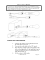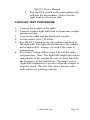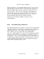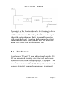
1
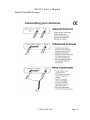
The Zero Power Smartuner
Catalog Number 54-26
April 2004
Thank you for buying your new SG211 Antenna Coupler. The SG-211
incorporates the very latest
American-made technology as well as
our experience in having delivered
more than 100,000 Smartuners since
1985. It is a state-of-the-art tuner
providing a new and unique level of
usefulness.
The concept of the SG-211 is quite
different from the rest of our line of
Smartuners. It is a unique departure
designed to provide flexible matching
capabilities in a portable environment
where power is at a premium. The
ease of installation and flexible
operation make this an ideal choice
when power is limited. We know that
the simplicity, reliability, and
flexibility of the SG-211 will enhance
your HF operation for years to come.
SGC continues to focus on providing
the most useful products and services
for our customers around the world.
Please feel free to call to discuss your
antenna system requirements at any
time. We look forward to making your
HF experience the very best.
Pierre Goral
Founder
1936-2004
Pamela Goral
President
Mailing: PO Box 3526, Bellevue, WA. 98009
Shipping: 13737 SE 26th St. Bellevue, WA. 98005
Toll Free: 800-259-7331 * Phone: 425-746-6310 * Fax: 425-746-6384
www.sgcworld.com * Email: [email protected]
SG-211 User’s Manual
Warnings
IMPORTANT NOTE: A random antenna wire will
radiate RF. Not only is this an RF Hazard within the
station, but it can cause local interference both within the
station and in the vicinity depending on your power level.
CAUTION: Unbalanced antennas are radiating from the
line as soon as they leave the SG-211. Minimize the
amount of wire inside the radio room to prevent
interference with electronic equipment. Minimizing
power will also minimize interference caused by this kind
of antenna.
© 2004 SGC Inc.
Page 1
SG-211 User’s Manual
Quick Start/Reference
© 2004 SGC Inc.
Page 2
SG-211 User’s Manual
Table of Contents
1
INTRODUCTION ................................................ 5
1.1
1.2
2
SPECIFICATIONS............................................. 5
MECHANICAL DESIGN ................................... 7
SG-211 SETUP ..................................................... 8
2.1
CONNECTIONS TO THE SG-211 ...................... 8
2.1.1
RF Input from your transceiver................ 8
2.1.2
Antenna and RF Ground Connections ..... 9
2.2
BATTERY REPLACEMENT............................. 11
3
ANTENNAS AND THE SG-211 ....................... 13
3.1
3.2
3.3
3.4
3.4.1
3.4.2
3.4.3
3.4.4
3.4.5
3.4.6
3.4.7
3.4.8
3.5
3.6
3.6.1
3.6.2
3.7
3.8
4
OPTIMUM COUPLING ................................... 13
CONNECTING ANTENNAS ............................. 13
BALANCED VS. UNBALANCED ANTENNAS ... 15
ANTENNA RECOMMENDATIONS................... 16
Dipoles ................................................... 16
The Inverted V Antenna.......................... 17
Dipoles with Matching Lines ................. 17
Long Wires & Inverted Ls ...................... 18
Vertical Antennas................................... 20
Loops...................................................... 23
Portable Antennas.................................. 24
Beams..................................................... 27
TIPS & TRICKS............................................. 27
REFERENCES ON ANTENNAS ........................ 29
From SGC .............................................. 29
Books...................................................... 29
THE GOLDEN RULES OF HF INSTALLATION . 30
DO-IT-YOURSELF LIGHT BULB TEST ........... 31
THEORY OF OPERATION ............................. 35
4.1
NO EXTERNAL POWER REQUIRED ............... 35
© 2004 SGC Inc.
Page 3
4.2
4.3
4.4
4.5
SG-211 User’s Manual
THE MATCHING NETWORK.......................... 36
THE SENSOR ................................................ 37
THE RELAY DRIVER MATRIX ...................... 38
MICROPROCESSOR ....................................... 39
5
COMPONENT LOCATION............................. 41
6
SCHEMATICS ................................................... 43
7
STANDARD WARRANTY............................... 48
© 2004 SGC Inc.
Page 4
SG-211 User’s Manual
1 Introduction
1.1 Specifications
The SG-211 is a revolution. You’ve never seen a coupler
so light weight or so flexible. Never has there been one so
easy to carry and use. And NEVER have you seen one
that will tune for 5 years on a single set of AA cells!
© 2004 SGC Inc.
Page 5
SG-211 User’s Manual
HF Frequency Range:
Power Input Range:
(approximate)
Minimum Sensitivity
Memory bins:
Input Impedance Range:
VSWR:
DC Input Requirement:
Input Current:
Random set time:
Recurrent set time:
Antenna Length:
Installation:
Operating Temperature:
Size:
Weight:
Case Construction:
Antenna types:
Power Source
Front Panel Connections
Rear Panel Connections
Indicators
1.8-60 MHz
60 watts (PEP) 30 watts key-down
30 watts (PEP) with short antennas below
3.5 Mhz
20 watts data continuous operation
Approximately 1 watt
256
.3-6000 ohms
Typically less than 2:1
None (internal battery)
Zero
Average 4 seconds
Typically less than 500 milliseconds
25 foot wire or whip from 1.8-60 Mhz
8 foot wire or whip from 3.5-60 Mhz
Any position
-30° to +60°C
8.66 inches X 4.69 inches X 1.55 inches
1 lb
Irridited Aluminum
1. Whip
2. Backstay (marine, sail)
3. Dipole centerfed
4. Dipole with feedline
5. Loop (small) 2x2 multi turn
6. Loop (large) 10 ft. and up single turn
7. Longwire
8. Ladder feed
9. Coaxial Fed Antennas
4 AA Batteries lasting 5 years
SO-239 RF Input Connector
Balanced and Unbalanced Wing Nuts
1 Red LED on Front Panel:
Steady for 2 seconds for tuned
Blinking for 2 seconds for not tunable
Morse B for 10 seconds for battery low
© 2004 SGC Inc.
Page 6
SG-211 User’s Manual
1.2 Mechanical Design
The SG-211 is in an Irridited Aluminum case.
The RF input connector is an SO-239 on the
front of the case. RF Output is from balanced
and unbalanced connectors on the back. Internal
construction makes the SG-211 suitable for
portable or fixed location use. Corrosionresistant hardware and passive alloys are used
throughout.
© 2004 SGC Inc.
Page 7
SG-211 User’s Manual
2 SG-211 Setup
Setup on the SG-211 is so easy there is almost nothing to
do. It comes with AA batteries already installed. All you
need to do is connect the coax from your transceiver,
attach your antenna to the terminals on the back, and the
SG-211 is ready to go.
2.1 Connections to the SG-211
2.1.1 RF Input from your transceiver
RF input to the SG-211 is through a standard SO-239
connector on the front. Choose good quality coaxial cable
with a PL-259 connector. You may want to add a
Power/SWR meter between the transceiver and the SG211 to monitor conditions. We recommend that you select
one that measures Forward and Reverse power as well as
SWR. This will provide more useful information about
conditions on the line.
© 2004 SGC Inc.
Page 8
SG-211 User’s Manual
2.1.2 Antenna and RF Ground
Connections
A wide variety of antennas can be connected to the SG211. A set of wing nuts for connecting balanced or
unbalanced antennas is provided on the back.
Optimum use of the SG-211 Smartuner is to put it directly
at the antenna feed point. This may require enclosing it in
a waterproof enclosure to protect it from the weather.
Either a balanced or an unbalanced antenna can be
connected directly to the wing nuts provided on the back
of the coupler.
If the Smartuner must be away from the antenna feed
point, it is best to connect to the antenna with balanced
feed line. The feed line can be connected to the balanced
terminals on the back of the coupler. When it is not
possible to use balanced feedline, then the antenna may be
connected with coax.
© 2004 SGC Inc.
Page 9
SG-211 User’s Manual
When feeding an unbalanced antenna directly, the RF
Ground lug is connected with a jumper strap to one side
of the balanced feed and the other side of the balanced
feed is used for RF Hot.
If you are feeding your antenna with coaxial cable, then
the cable is connected to the back panel by connecting the
center conductor to the right RF Out connection and the
braid to the Chassis Ground with a jumper to the left RF
Out connection as shown below.
© 2004 SGC Inc.
Page 10
SG-211 User’s Manual
A short pigtail connector with an SO-239 female
connector on it will make it easier to use Coaxial cable
with the SG-211.
2.2 Battery Replacement
To replace the batteries inside the SG-211, you must
unscrew the cover and remove it. The screws are on the
left and right sides of the SG-211 as shown below.
Two Cover Screws on
each side, none on front
and back
The batteries are in two battery holders on the SG-211
circuit board. Any suitable alkaline AA batteries may be
© 2004 SGC Inc.
Page 11
SG-211 User’s Manual
used. We recommend using the highest quality alkaline
AA batteries available to assure the longest life with no
battery leakage that could damage the circuit board.
Batteries
© 2004 SGC Inc.
Page 12
SG-211 User’s Manual
3 Antennas and the SG-211
The SG-211 can accommodate a wide variety of antennas.
3.1 Optimum Coupling
Optimum use of the SG-211 is to place it at the antenna
feed point. This keeps SWR on the feed line to an
absolute minimum.
3.2 Connecting Antennas
The SG-211 is provided with an SO-239 connector on the
front panel for RF in. It has balanced and unbalanced
connections on the back panel.
© 2004 SGC Inc.
Page 13
SG-211 User’s Manual
The SO-239 connector is intended to connect to a normal
Coaxial feedline.
Unbalanced antennas,
such as a long or random
wire, are fed by
connecting the radiator to
the right RF Out
connection and the RF
Grounding system to the
left RF Out and Chassis
Ground.
IMPORTANT NOTE: Antenna wire connected to the SG211 directly will radiate RF. This is an RF Hazard and it
can cause local interference within the station and in the
vicinity depending on your power level.
The balanced feed connection supports ladder line feed to
a balanced antenna such as a dipole or a loop.
© 2004 SGC Inc.
Page 14
SG-211 User’s Manual
3.3 Balanced vs. Unbalanced
Antennas
The distinction
between balanced and
unbalanced antennas
is that balanced
antennas are
electrically balanced
at the feed point while
unbalanced antennas
require an RF Ground
to provide the balance. Dipoles and loops are typical
balanced antennas.
Unbalanced antennas need an RF Ground such as a radial
wire system or a
counterpoise to create
electrical balance. They
depend on the quality of
the ground for a maximum
radiated signal. Without a
good quality ground,
unbalanced antennas will
cause interference, RF in the radio room, and radiate
poorly. Long wires and verticals are typical unbalanced
antennas.
© 2004 SGC Inc.
Page 15
SG-211 User’s Manual
3.4 Antenna Recommendations
There are many ways to connect antennas for use. Here
are some common examples that can help you get started
with your SG-211. For additional information about
antennas, we recommend that you obtain a copy of our
HF User’s Guide from our website at
http://www.sgcworld.com/ftp/Books/hfguide.pdf
For detailed technical information about antennas, the
consistently best source is the ARRL Antenna Handbook.
3.4.1 Dipoles
Balanced antennas are
connected to the
balanced line terminals
on the back of the SG211.
Some balanced
antennas, such as the
folded dipole are
usually constructed
with a coax feed at
the center point.
Simply connect your
coax feed line to the
SG-211 as shown.
© 2004 SGC Inc.
Page 16
SG-211 User’s Manual
3.4.2 The Inverted V Antenna
The Inverted-V
antenna can be fed
with ladder line run
from the balanced line
connection on the SG211. It is also
commonly fed from
coaxial cable with the
center conductor to one side and the shield to the other.
3.4.3 Dipoles with Matching Lines
Some antennas, such as the G5RV, use a section of ladder
line as a matching device. The ladder line transforms the
feed point impedance to something near 50 ohms at the
antenna’s design frequency. Usually, the ladder line
terminates in a 1:1 balun. Coaxial line from the
transceiver connects to the balun.
© 2004 SGC Inc.
Page 17
SG-211 User’s Manual
When operated away from the design frequency, these
antennas need a tuner such as the SG-211 to match the
coaxial line from the transceiver. The SG-211 can be used
with either coaxial cable on output to the balun or direct
connected to the ladder line section with the balun
removed.
3.4.4 Long Wires & Inverted Ls
Long wire and inverted L antennas are unbalanced
antennas. They are fed from the right RF Out connection
directly with a single wire. The RF Ground system is
connected to the Chassis Ground and that is jumpered to
the left RF Out connector.
CAUTION: Unbalanced antennas are radiating from the
line as soon as they leave the SG-211. Minimize the
amount of wire inside the radio room to prevent
interference with electronic equipment. Minimizing
© 2004 SGC Inc.
Page 18
SG-211 User’s Manual
power will also minimize interference caused by this kind
of antenna.
More than any other factor, a good RF ground will help to
improve the radiated signal from these antennas and
minimize RFI generated by the antenna.
As a minimum, an RF Ground can consist of a wire 510% longer than the wire antenna and laid out so that it
does not cross over itself or form a loop. A far better RF
ground can be constructed by adding ground radials
connected to the Chassis Ground connector of the SG211.
© 2004 SGC Inc.
Page 19
SG-211 User’s Manual
3.4.5 Vertical Antennas
A vertical antenna may be
connected to the SG-211 in a
number of ways. Vertical
antennas require an RF
Ground system to function
properly, but this may be
incorporated into the design
of the antenna itself.
A typical vertical antenna is
the GROUND PLANE that
includes radials in the
design. This, and many other vertical antennas use an SO239 connector or equivalent to feed the antenna. This type
of antenna can be connected directly to the SG-239 or via
a pigtail as shown below.
Any vertical antenna fed with Coaxial cable can be
connected in this way.
© 2004 SGC Inc.
Page 20
SG-211 User’s Manual
Home made vertical
antennas are commonly
made in one of two
ways. A very common
type of construction
builds the radial system
at the base of the
antenna. Flagpole
antennas are normally
built in this way. Coax
line can be run from the SG-211 to the base of the
antenna. The center lead of the coax will feed the
radiating element in the flagpole vertical while the coax
shield will be connected to the RF grounding system.
Another way that a vertical can be fed is to have it fed
with a wire directly from the SG-211 right-most RF hot
terminal to the radiating element.
To the Radiating
Element
© 2004 SGC Inc.
Page 21
SG-211 User’s Manual
The RF ground system is connected to the Chassis ground
which should be connected by a jumper to the left RF Hot
post.
RF Ground system
connection
If you are using coaxial cable to connect the antenna, then
the center conductor goes to the right-most RF Hot post
and the braid goes to the left most which is jumpered to
the Chassis ground post as shown.
A properly installed antenna should not have RF power
getting on the outside of the coaxial line.
© 2004 SGC Inc.
Page 22
SG-211 User’s Manual
3.4.6 Loops
Loop antennas are balanced antennas. They are very
simple to feed from balanced feed line. Ideally, the SG211 will be at the loop feed point, but when it must be at
some distance from the feed point, balanced feedline will
tolerate the SWR better between the antenna and the SG211 than will coaxial cable. A loop is connected to the
SG-211 at the two RF Out connectors.
Loops can be
conveniently
arranged either
horizontally or
vertically. The
feeding
arrangement is the
same.
Loops can take on nearly
any closed shape such as a
square, rectangle, triangle, or
diamond shape and they can
be fed on the sides or in the
corners. The effect of
different configurations and
feed points is well documented in the many books on
antennas.
It is also possible to feed a loop from a coaxial cable by
connecting one side of the feed point to the center
© 2004 SGC Inc.
Page 23
SG-211 User’s Manual
conductor and the other side of the feed point to the coax
shield.
3.4.7 Portable Antennas
Portable whip antennas make excellent radiators and can
be used in a number of configurations. Examples include
fixed whip antennas like SGC’s SG-307 whip and 10 foot
collapsible whips available from a number of vendors.
One popular antenna uses a whip erected as a vertical
antenna with radial wires extending from its base. There
are a number of stands available commercially or a simple
stand can be created with an antenna mounting and
several pieces of wood.
© 2004 SGC Inc.
Page 24
SG-211 User’s Manual
Another antenna built using whips is a horizontal dipole
with two whips, one on each side of the feed point
mounted to create a balanced dipole. A pair of SG-307
whips in this configuration will be tunable from 1.8 to 60
Mhz. Ten foot collapsible whips will be tunable from 3.5
to 60 Mhz.
Representative sources for the equipment you will need to
assemble one of these portable antennas are:
© 2004 SGC Inc.
Page 25
SG-211 User’s Manual
Tripod
Mast
Tripod&Mast
Tee Mount
Whips
Buddipole
Tripod
Buddipole
Mast
16 Foot
Buddipole
Mast
12-30 Foot
Painter’s Pole
6 Foot Portable
Antenna Stand
Center Tee
Mount
SG-307
Helically
Wound Whip
10 & 12 Foot
Extra Long
Whips
Replacement
Whips #2701408B
AT271/A
Collapsible
Whip
© 2004 SGC Inc.
W3FF
W3FF
W3FF
Costco
Home Depot
Most Hardware
Stores
MFJ
W3FF
SGC
MFJ
Radio Shack
APEX
Page 26
SG-211 User’s Manual
Check the following web sites for current prices and
ordering information:
APEX
MFJ
Radio Shack
SGC
W3FF
Brooklyn. NY
http://www.mfjenterprises.com
http://www.radioshack.com
http://www.sgcworld.com
http://www.buddipole.com
3.4.8 Beams
The radiating element of a beam is a dipole antenna fed
with coaxial cable. Connecting a beam to the SG-211 is
accomplished by connecting the coax to a coax pigtail.
3.5 Tips & Tricks
1.
The most frequent source of problems in
unbalanced antenna systems is the RF Ground.
RF grounding is frequently misunderstood and
poorly implemented. See our book The HF
User’s Guide available free for download from
www.sgcworld.com.
2.
Be aware of the difference between a SAFETY
ground and an RF ground. Safety grounding is
necessary to protect your life and property from
coming into contact with lethal doses of
electricity. RF grounds, when required, are
necessary to the operation of your antenna
system. Connecting the two together can inject
© 2004 SGC Inc.
Page 27
SG-211 User’s Manual
RF into your other electronic equipment and
VICE VERSA. Your other electronics can inject
RF Noise into your receiver and obliterate your
received signal completely.
3.
Plan your antenna installation carefully!
4.
Don’t commit to a final installation until you
have tried out your antennas in as near to final
form as possible.
© 2004 SGC Inc.
Page 28
SG-211 User’s Manual
3.6 References on Antennas
3.6.1 From SGC
SGC, HF User’s Guide, available free from
http://www.sgcworld.com/ftp/Books/hfguide.pdf
SGC, Stealth Antenna Manual, available free from
http://www.sgcworld.com/ftp/Books/STEALTHman.pdf
SGC, Smartuners for Stealth Antennas,
http://www.sgcworld.com/ftp/Books/stealth.pdf
3.6.2 Books
Carr, Joseph, Practical Antenna Handbook, 3rd Edition,
McGraw-Hill, New York, 1998.
Hale, Bruce, Editor, The ARRL Handbook, ARRL,
Newington, Ct., 1988.
Hall, Gerald, Editor, The ARRL Antenna Book, ARRL,
Newington, Ct., 1991
Kleinschmidt, Kirk, Stealth Amateur Radio, ARRL,
Newington, Ct., 2001.
© 2004 SGC Inc.
Page 29
SG-211 User’s Manual
3.7 The Golden Rules of HF
Installation
These rules apply to all types of stations, including base,
mobile, air-borne and marine. They are very important for
planning and installing your HF system, if you want to
achieve good communications.
1.
2.
3.
4.
5.
Install the transceiver as close to operation
site and power supply system as possible
(whether it is an external power supply or
battery system).
The antenna must be installed in an open
space and as far as possible from your
operating point. Example: on a sailboat use
the backstay as the antenna, since it is the
farthest point away from the rest of the
vessel.
The antenna coupler should be installed at
the feed point of the antenna.
Always create your own ground with radial
wire or copper straps. They are the only
ones that will guarantee a solid and proper
ground system.
All cables - power supply, control or coaxial
- must always be as short as possible and/or
necessary. Any excess cable should be
shortened to the proper length - never coiled.
Following these rules will minimize marginal installations
and problem sources such as RF feedback in the radio,
power supply or cables and “hot” or RF burning
microphones. If all 5 above points are followed during the
© 2004 SGC Inc.
Page 30
SG-211 User’s Manual
design and installation of your HF system, the operator
can expect top performance. Further information
regarding applications, installation and operation can be
downloaded from our website www.sgcworld.com. These
publications include:
•
•
•
•
HF User’s Guide
Go Mobile at 500 Watts
Stealth Antennas
Smartuner Antenna Coupler
Manuals
3.8 Do-it-Yourself Light Bulb Test
Any time a transmitter is used, its output must go to a
load. A load is anything that the output power can be
pumped into. If the transmitter is operated without a load
connected, the final amplifier stage could be severely
damaged. Never test a transmitter on the air for the first
time if you are unsure about how to operate it or if you
are unsure whether it is working properly. You could
create harmful interference to other stations.
To test transmitters without actually operating into an
antenna, dummy loads were created. A dummy load is a
load that will dissipate the energy from the transmitter
instead of emanating it into the ionosphere. Nearly all
commercial dummy loads are large oil-filled cans. These
dummy loads change the transmitted energy into heat,
which is absorbed by the oil. Because different
transmitters output different amounts of power, different
sizes of dummy loads must be used. Dummy loads for
typical amateur powers (<500 watts) are relatively
inexpensive and are readily available.
© 2004 SGC Inc.
Page 31
SG-211 User’s Manual
Unfortunately, when you use a can-type dummy load, you
can’t see “what’s happening” with your transmitter. In
this case, you can use a light-bulb dummy load to test
your transmitter. Here, the light bulb is directly connected
to the output of the transmitter and it dissipates the RF
energy as light. The light bulb dummy load is more useful
than the oil-can type because you can guess how much
power is being output, you can see the voice modulate the
SSB (the light will flicker with your voice peaks), and
you can tune the transmitter for maximum out-put (if the
transmitter is an older model that requires tuning).
Before building or using the light-bulb dummy load,
remember that these models typically don’t dissipate the
transmitter’s output as well as an oilcan dummy load. The
result is that RF will “leak” out; we have heard a few
stories of amateurs who were heard around town while
operating their transmitters into a light-bulb dummy load.
If you use this system, make sure that you test the
equipment on a clear, harmless frequency (NEVER test
with the transmitter set on an emergency frequency, such
as 2182 KHz).
SGC recommends that you build the light-bulb dummy
load with the following parts (although we have made one
with an old light fixture and a makeshift version with just
alligator clip leads and a light bulb):
•
•
•
•
•
•
AC socket to cable with a PL-259 connector
(for transceiver)
AC socket to cable with alligator clips
(needed with coupler)
Light bulb to AC adapter
3 to 25 watt light bulb, 120 to 220 VAC
10-60 watt radio transceiver
Any SGC Smartuner or equivalent
© 2004 SGC Inc.
Page 32
SG-211 User’s Manual
ATTENTION: Some retuning may take place as the impedance of the
light bulb varies with the power level. If the power level is held constant
with a continuous carrier such as produced by CW mode operation, the
coupler setting will settle after a short period of time.
RADIO TEST PROCEDURE
1.
2.
3.
4.
Connect the transceiver light bulb load to
the radio RF in/out jack.
Turn on the radio and set the CW mode.
Key the PTT switch on the microphone and
look at the light bulb. If the light bulb load is
connected and the radio is transmitting, the
light should turn on.
Set the radio to SSB mode.
© 2004 SGC Inc.
Page 33
5.
SG-211 User’s Manual
Key the PTT switch on the microphone and
talk into the microphone. Notice that the
light turns on when you talk.
COUPLER TEST PROCEDURE
1.
2.
3.
4.
5.
6.
Connect the coupler to the radio.
Connect coupler light bulb load to Smartuner coupler
antenna out-put.
Turn on the radio and the Smartuner coupler.
Set the radio to the CW mode.
Key the PTT switch on the microphone and look at
the light bulb. The light should turn on if the coupler
has completed its’ tuning cycle and if the radio is
transmitting.
For further testing, follow steps 4 & 5 of the radio
test procedure. Note: The light bulb might not turn on
immediately if the coupler has not yet been tuned for
the frequency of the transmitter. The output power
(light-bulb brightness) is greatest when the coupler is
properly tuned. This test will ensure that the radio
and coupler are working properly.
© 2004 SGC Inc.
Page 34
SG-211 User’s Manual
4 Theory of Operation
4.1
Antenna
Transmitter
Antenna
Transmitter
The SG-211 tuner is built around the L network. An L
network as viewed from the transceiver may be
configured with the shunt reactance on the input or the
output as shown below:
No External Power Required
The SG-211 automatic antenna tuner is unique. It requires
no external source of power. This means that the unit can
be located remotely without the inconvenience of
additional wiring to provide power. For portable use, the
antenna tuner draws no power from station batteries.
© 2004 SGC Inc.
Page 35
SG-211 User’s Manual
With normal use, the internal batteries have a service life
that approaches the shelf life of the batteries themselves.
Battery replacement will be required at intervals of five
years or more. The very low average current drain is
achieved by using low power latching relays that draw
power only during the matching process. A very low
power standby mode for the sensors and the
microprocessor limits standby current to a few
microamperes.
4.2
The Matching Network
The matching network consists of a four-to-one step down
transformer that also performs an unbalanced to balanced
matching function. The output of the transformer T1,
at12.5 ohms, serves as the input to an adjustable L
network. Shunt inductor L1 across the transformer output
steps down the effective impedance, especially at lower
frequencies. The L network transforms the impedance up
to match the complex impedance of the antenna. This is a
well established matching concept in military manpack
applications spanning many years.
© 2004 SGC Inc.
Page 36
SG-211 User’s Manual
The output of the L network can be left floating to drive
balanced antennas or one side can be grounded for
unbalanced antennas. Providing the balun on the input
side of the network means that it is normally operated
with a matched load. Locating the balun on the output
side as in some other tuners, means that the balun sees
much more stress with a mismatched load.
4.3
The Sensor
Transformers T2 and T3 form a directional coupler. D1,
D2 and associated circuitry detect forward and reverse
power that is fed to the microprocessor A/D inputs. The
microprocessor wakes up when the forward power
exceeds the minimum threshold. If significant reflected
power is detected, the matching sequence is initiated.
© 2004 SGC Inc.
Page 37
SG-211 User’s Manual
4.4
The Relay Driver Matrix
Page one of the schematic diagram shows the matrix used
to drive the relay coils. The latching relays have two
coils; one for turn-on and one for turn-off. With 16 relays,
the circuit needs to drive 32 coils. A matrix of six
columns and six rows allows selection of 36 coils with
only 12 microprocessor outputs.
© 2004 SGC Inc.
Page 38
SG-211 User’s Manual
A diode pair is associated with each coil. The series
diode provides isolation necessary for proper operation of
the matrix. The shunt diode prevents voltage spikes on
turnoff.
Extensive capacitor bypassing is used to prevent RF from
interfering with the proper operation of the matrix.
On page two of the schematic diagram transistors Q1
through Q12 provide pulldown drive for the rows and
pullup drive for the columns of the matrix.
4.5
Microprocessor
A PIC flash microprocessor was selected for the very low
sleep mode current drain that is key to long battery life.
Inputs to the microprocessor are forward and reverse
power, and a sample of the input signal from which the
frequency is measured. The frequency measurement
makes it possible for the processor to store historical
values for a correct match over the frequency range.
Thus, when changing frequency, the previous values are
recalled, greatly speeding the matching process.
U2 provides a reference to one of the A/D inputs to
measure battery voltage. The processor flashes LED DS1
when a low battery condition is detected.
© 2004 SGC Inc.
Page 39
SG-211 User’s Manual
Because a flash programmable microprocessor is used,
software can be changed without removing the processor
or proms. J1 provides connection to the programmer for
this purpose.
Since the processor is dormant except during the actual
matching process, the possibility of generating RF
interference in the receiver is eliminated.
© 2004 SGC Inc.
Page 40
SG-211 User’s Manual
7 Standard Warranty
SGC LIMITED PRODUCT WARRANTY
(1 Year Parts and Labor)
And SOFTWARE LICENSE
You have purchased an SGC equipment product together with a license to use the
software installed in that product. Please return the warranty registration card that
accompanies this product, so that we can assure that you receive proper warranty
service and important notices that may affect the product. This SGC product is
warranted to be free from defects in workmanship and material for a period of 1
year from the original buyer’s date of purchase. In the event of a defect,
malfunction or failure of which SGC receives notice during the 1 year period,
SGC, at its’ option, will repair or replace the product free of charge to the buyer.
The buyer must contact SGC for a Return Material Authorization Number (RMA)
and deliver the product back to SGC with this RMA number and written proof as
to date of purchase. SGC will ship a new or repaired product to the buyer,
reserving discretionary right to return a newer model that offers at least equal
performance. The foregoing warranty extends to the original buyer and does not
include (1) buyer’s cost to return the product to SGC, (2) buyer’s costs to remove
or reinstall the product for warranty work, or (3) added costs of special expedited
shipment that may be requested by buyer. Except for the limited warranty stated
above, and to the full extent permitted by law, SGC disclaims any other express or
implied warranties and liability for any incidental, consequential, special or
exemplary damages in connection with its product, even if SGC or its agents are
advised that such damages are foreseeable. (Note: Some states do not allow the
exclusion or limitation of incidental or consequential damages, so the above
exclusion may not apply to you). There is no warranty with respect to (1) the
product’s transmission range or geographical coverage which can vary by location
(2) non-performance caused by using an inadequate or improper antenna or
grounding system or (3) routine maintenance, periodic adjustment and
performance testing of the product or system. SGC customarily charges a flat fee
for repairs performed outside of the warranty coverage. To inquire about such
charges, please contact SGC.
END USER SOFTWARE LICENSE
SGC warrants that the SOFTWARE included in this product will perform in substantial
accordance with the documentation. SGC grants to the original end user of its product a nonexclusive worldwide license to operate the software installed therein. This license shall be
transferred to any person or entity that subsequently acquires lawful ownership of the product.
This license shall be limited to using the software for contemplated operation of SGC’s product.
This license does not permit any end user to (a) modify or adapt SGC’s software or to merge it
into another program (b) reverse engineer, disassemble, or otherwise attempt to discover SGC’s
software source code or © sub license or otherwise transfer SGC’s software for any use other
than operating the product originally purchased from SGC.
© 2004 SGC Inc.
Page 48
Description
HF Frequency Range
Power Input Range (PEP watts)
SG-239
1.8 - 30MHz
SG-237
1.8 - 60MHz
SG-230
1.6 - 30MHz
SG-231
1 - 60MHz
SG-235
1.8 - 30MHz
1.5-200
3-100
3-200
3-100
3-500
Continuous CW Power (watts)
80
40
80
60
200
Input Impedance Range (ohms)
45-55
45-55
45-55
45-55
45-55
VSWR (Typical)
<2:1
<2:1
<2:1
<1.4:1
<1.4:1
13.8
10 to 18.5
13.6
10 to 18
13.6
10 to 18
13.6
10 to 18
13.6
10 to 18
Input Current (average amps)
Random Set Times (seconds)
0.23
<2
0.3
<4
0.9
<2
0.5
<4
1.4
<2
Recurrent Set Times(millisec)
<10
<10
<10
<10
<10
Non-Volatile Memory Addresses
170
170
170
170
170
1/8 million
40 feet min.
half million
8 feet min.
half million
8 feet min.
four million
8 feet min.
half million
50 feet min.
100 feet min.
28 feet min.
23 feet min.
23 feet min.
315 feet min.
Pi & L
Pi & L
Pi & L
Pi & L
Pi & L
50pf
3150pf
0.25µH
15.875µH
50pf
6400pf
0.125µH
32µH
100pf
6400pf
0.25µH
64µH
50pf
6400pf
0.125µH
64µH
100pf
6400pf
0.125µH
32µH
50pf
740pf
12.5pf
200pf
25pf
800pf
12.5pf
400pf
12.5pf
400pf
DC Input Requirement (VDC) Nominal
DC Operating Range (VDC)
Total combinations using all elements
Antenna Length operating higher than 3.3 MHz
Antenna Length operating from the lowest
frequency to 3.3 MHz
Elements configuration
Input Capacitance minimum
Input Capacitance maximum
Inductance minimum
Inductance maximum
Output Capacitance minimum
Output Capacitance maximum
Installation
Any position
Any position
Any position
Any position
Any position
Operating Temperature (Celsius)
Environmental
-35C to +70C
None
-35C to +70C
Waterproof at
immersion of
two feet, half
hour
-35C to +70C
Waterproof at
immersion of two
feet, half hour
-35C to +70C
Waterproof at
immersion of
two feet, half
hour
-35C to +70C
Waterproof at
immersion of two
feet, half hour
Size Overall (inches)
7.5Dx6Wx1.85 6Dx7Wx1.5H
H
(5.5x6x1.7 PCB
Only)
16Dx12Wx3H
11.5Dx9.5Wx1.7
H
16Dx12Wx3H
Size Overall (centimeters)
19Dx15Wx5H 22.9Dx17.8Wx3
.8H
40.6Dx
30.5Wx7.6H
29.2Dx
24.1Wx4.32H
40.6Dx
30.5Wx7.6H
Weight (pounds)
2 lbs.
<2
8
3.8
8
Weight (kilos)
.75 kg
<0.75
3.5
1.6
3.5
Case Construction
Aluminum
Case
Cable(s) (NOTE: All couplers require RF and 12
volt lines only. SGC cables are required for
additional features only.)
Terminals
Plastic ABS
Waterproof
metal base
SGC cable, 9
feet coaxial and
two power wire
input, and RMT
tune and
SmartLock wire.
Plastic ABS
Plastic ABS
Waterproof case Waterproof case
metal base
SGC cable, 9 feet 10 feet RG-58
power cable, 10
coaxial and two
power wire input, feet RG-58 coax
and RMT tune
cable with
and SmartLock
PL259
wire
connectors
Plastic ABS
Waterproof case
SGC cable, 9 feet
coaxial and two
power wire input,
and RMT tune
and SmartLock
wire.
A Perfect Complement
to the SG-211
The SG-2020
Use it at your base or in your backpack or travel bag. The
SG-2020 goes where you want to go!
Specifications
Operating Modes
Frequency Range
Dimensions
Approximate Weight
DC Voltage
Total current (receive)
Transmitter power
USB, LSB and CW
1.8-29.7 MHz
7.25”L x 6”W x 2.75”H
18.5cm x 15cm x 7cm
4.5 lbs. (2kg)
10-18 VDC
Typical 400mA
Adjustable from 0-20W PEP
All the Power you’ll need for base, backpack or business travel
Mailing: PO Box 3526, Bellevue, WA. 98009
Shipping: 13737 SE 26th St. Bellevue, WA. 98005
Toll Free: 800-259-7331 * Phone: 425-746-6310 * Fax: 425-746-6384
www.sgcworld.com * Email: [email protected]