1
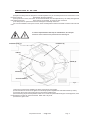
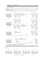
COEF srl.
Via Albinatico, 80-82
51019 Ponte Buggianese (PT)
ITALY
www.coef.it / www.coef.net
Sirio 150 / 150DV
Graphic by PC CAD & VIDEO
[email protected]
•
Code 02E010 - Sirio 150
•
Code 02E011 - Sirio 150DV
• OPERATING INSTRUCTIONS
Revision 1
INTRODUCTION
Thank you for using the Sirio 150 / 150DV !
The Sirio 150 / 150DV projects, thanks to an extremely efficient optic system (international patent n. WO99/40361), a powerful
light beam which can create numberless color shades. Its performances, in terms of luminousity and lighted surfaces, can reach incredible levels.
The Sirio 150 / 150DV comes in two versions:
• Cod. 02B010 Sirio 150 for Mastercolour 150W (CDM-T 150W/942 - CDM-SA/T 150W/942).
• Cod. 02B011 Sirio 150DV with shutter for Mastercolour 150W (CDM-T 150W/942 - CDM-SA/T 150W/942).
The Sirio 150 / 150DV can work in automatic mode or in synchro mode, otherwise may be controlled by 8 bit DMX controllers.
The input protocol is the DMX 512. To drive the Sirio 150 / 150DV we suggest to use our controller MasterShow 512.
To make the most of its possibilites and for a correct functioning of this unit in the years to come, we suggest you to read
carefully this manual before connecting or putting the spot into use. By doing so you will gain experience with its commands and
connections and you will be easily able to use it.
ATTENTION: carefully read the directions of this manual. Exclusively follow the safety rules in force and do not carry
out assembly and/or maintenance operations without taking all precautions as indicated in the different sections or
without the necessary specialization.
This manual must always accompany the equipment, therefore it must be available and readable at any moment if
necessary. Also in case of sale, rent, change of place and/or ownership, these documents shall be enclosed with the
relative equipment.
ADVICES FOR A CORRECT INSTALLATION
This equipment is destined to an exclusively Professional use.
READ ALL CAUTIONS AND WARNINGS PRIOR TO OPERATE THIS EQUIPMENT.Instruction to prevent injury or damage
due to electric shock, fire, mechanical hazards and UV radiation hazards.
•PROTECTION AGAINTS FIRE
1)This equipment is designed for use with the following lamps only: Mastercolour 150W • CDM-T 150W/942 • CDM-SA/T
150W/942. Do not use any other type of lamp!
2) Maintain minimum distance of 0.3 meter from walls or any other type flammable surfaces.
3) Maintain minimum distance of 1.0 meter to lighted objects .
4) Replace fuses only with the specified type and rating.
5) Do not install the spot close to heat sources. Do not lay the connection cable on the spot when it is warm.
•PROTECTION AGAINST ELECTRIC SHOCK
1) This equipment must be earthed.
2) Class I equipment. The power supply cord includes a protective earthing conductor as part of the cord.
3) For connection to the mains supply proceed as pict.3 page 6.
4) Disconnect power before installing the lamp or servicing (service personnel).
•PROTECTION AGAINST MECHANICAL HAZARDS
1) Use secondary safety chain when fixing this equipment.
2) Hot lamp explosion hazard. Do not open the equipment for 300 seconds after switching off.
3) Equipment surface may reach temperature up to 90°C. Allow about five minutes before handling.
4) Replace the lamp if it is damaged or thermally deformed and however after 6000 life hours.
•PROTECTION AGAINST UV RADIATION HAZARDS
1) Do not start on this equipment without lamp enclosure or if the protection screens, or ultraviolets screens are damaged.
2) The protection screens, the lenses, or the ultraviolet filters must be replaced if they are visibly damaged and their effectiveness has been reduced, for example, by cracks or deep scratches.
3) Do not look directly at the lamp while lamp is on.t
Declaration of CE conformity
COEF srl. Via Albinatico, 80-82 / 51019 Ponte Buggianese (Pistoia) ITALY
Declare that the product Sirio 150 / 150DV is in conformity with 89/336 EEC-EMC directive and
with the actual required safety standars in accordance with LVD 73/23 EEC
Pag. 2
http://www.coef.it
-
[email protected]
DANGER SIGNAL: Generic dager signal and electric shock danger signal.
GENERAL WARRANTY CONDITIONS
•
•
•
•
•
•
•
•
The guarantee is valid for a period of 12 months from the date of purchase of the equipment.
The guarantee is not valid in case a wrong voltage or frequency is selected.
The parts which are proved to have manufacturing defects are also covered by the guarantee.
The external parts of the equipment, its removable elements and lamps are excluded from the guarantee; for these
parts we recommend to follow the directions supplied by their manufacturers.
The guarantee is not valid in case of tampering or repairs carried out by non-authorized personnel.
The replacement of the equipment during the validity of the guarantee is not provided for.
The transport freights from and to the manufacturer for repairs under guarantee are at Customer’s charge.
When applying for the repair, always mention the serial number and the model of the equipment.
PACKING CONTENTS
Carefully check the contents of the packaging and the completeness of the components. If any of the parts listed hereunder is
missing, please contact your Dealer immediately:
•
•
•
•
Sirio 150 / 150DV complet unit
This user manual
Lamp (upon request)
Wall fixing plate
PROTECT NATURE.
DO NOT DISPOSE OF THE PACKAGING IN THE ENVIRONMENT.
CAREFULLY KEEP THE BOX AND THE COMPONENTS OF THE PACKAGING FOR ANY DISPLACEMENT
OR RE-SHIPMENT OF THE EQUIPMENT.
Do not leave the packaging elements (polystyrene, nylon, metal parts, etc.) unattended.
TECHNICAL NOTES
• LAMP
Mastercolour CDM-T 150W/942 or CDM-SA/T 150W/942)
Averange lamp life: 6000 hours
Colour temperature: 4200 K
Luminous flux: 14000 lumen
Colour rendering index: 96 Ra
• OPTIC/COLOUR SYSTEM
New concept optical system (patent pending)
Full CYM color mixing, unlimited variety of colours and shades
High resolution stepper motors
Colour crossfades can be programmed at four different speeds or in real time
•DIMMER (for code 02B011 only)
0-100% continuosly variable (256 steps)
• CONTROL INPUT
Interface standard: RS-485; opto-coupled input
Protocol: USITT DMX 512
Stand-alone control: auto mode function master/slave (synchro mode)
• POWER SUPPLY
Rated voltage: 230 Vac • on request: 208 Vac 60 Hz; 200 Vac 50 Hz
Rated frequency: 50 or 60 Hz
Rated current: 1.1A
Rated power: 250 Va
• FUSES
Lamp fuse: 3.15A/250V T (time-delay)
Electronics fuse: 1.6A/250V T (time delay)
http://www.coef.net - [email protected]
Pag. 3
DMX IN - DMX OUT
fig.1
POWER INPUT
The equipment must be earthed. If this rule is not followed, the warranty
will be void. IP 66 grade: to ensure the declared IP grade choose the
correct size of the cables (from 3 to 6.5mm). All the gaskets and the glass
must be keeped in full working order.
BEFORE USING
Read all cautions and warnings to page 1 prior to install this equipment. Particularly, read the following:
Before connecting the equipment to the power system:
1) Make sure that the mains voltage and frequency correspond to rated values shown on the label
(pict.1).
2) Connect the mains power cable to the electronic boards inside and if necessary (synchro-mode) the
DMX cable.
The Sirio 150 / 150DV is made for a mains voltage 230V 50 Hz; 1,1A
For a power supply of 100V-120V it is necessary to use one auto transformer with the following features:
• Output voltage 230V.
• Output current 2A.
Before any operation on the fixture
a)
Disconnect power before lamp’s replacement (page 5) or servicing (service personnel).
b)
Do not open the lamp cover for 300 seconds after switching off.
c)
Wear gloves and goggles to re-lamping (page 5) or to work inside the unit (service personnel).
Do not install the spot close to heat sources. Do not lay the connection cable on the spot when it is warm.
The unit must be positioned at least 30 cm. from walls or other flammable surfaces and minimum 1.0 meter to
lighted objects.
External surfaces temperature:
• After 5 minutes work; Tc=75°C. • Once the thermic balance has been obtained; Tc=90°C.t
Pag. 4
http://www.coef.it
-
[email protected]
INSTALLATION OF THE LAMP
d) Replace the lamp when the lamp life is exhausted (6000 hours) to avoid bad peformances of the fixture or that
the optic system is
damaged by the lamp explosion.
e) The protection screens, the lenses, or the ultraviolet filters must be replaced if they are visibly damaged and
their effectiveness has
been reduced, for example, by cracks or deep scratches.
f) The lamp must be replaced if it has been damaged or thermally deformed.
g) In case of installation of the spot to a truss, check carefully that the fixture is fixed with a chain to both truss and
unit.
In case of replacement of the lamp or maintenance, do not open
the fixture unless 5 minutes have passed from the switching off.
DICHROIC BLADE (C)
PARABOLE (D)
LAMP (E)
SCREW (B)
SCREW (A)
SHUTTER BLADE (F)
fig.2
1) Disconnect power before installing the lamp. Wear gloves and goggles.
2) Unscrews the four screws on the glass cover and fully open the eight dichroic and shutter blades (C and F ).
3) Unscrews the screws A and B and remove the reflector parabole (D).
4) Insert the lamp (E) into the lampholder socket. Do not touch the quarz bulb with fingers. If this happenes, clean
the bulb before use with dry cloth and alcohol. Polish with a dry cloth.
5) Screws the glass cover.
http://www.coef.net - [email protected]
Pag. 5
CONNECTION TO THE MAINS POWER AND TO THE DMX SIGNAL / REPLACING FUSES
To connect the Sirio 150 / 150DV to the mains power, remove the cover located behind the fixture, and connect
the cable to the electronic board as shown in pict. 3.
The connection to the DMX signal to the Sirio 150 / 150DV must be made by using standard DMX cables as
shown in pict. 3/a
HIGH VOLTAGE!
Always disconnect the mains supply before opening the connections
area. To ensure the IP66 rate choose the correct size of the cables (from 3 to
6.5 mm.)
In order to avoid any problem in the signal transmission, it is warmly suggested to use a cable for high speed data
transmission.
The usage of a normal microphonic or audio cable is suggested only for lines max 100 mts long.
If the lines have a total length over 150-200 mts it is suggested to use any DMX Repeater Amplifier
MAINS VOLTAGE CABLE 230Vac/
Fig. 3
Fig. 3/a
DMX CABLE
DMX TERMINAL LINE
The wrong connection of the terminal line or its non-connection are probably the most frequent reasons for the
defective functioning of the DMX line. The terminator is a terminal resistor fitted at the end of the cable furthest from
the transmitter.
The terminal resistor should have the same value as the impedance of the connection cable.
We suggest to use a terminal with a 100 ohm resistor.
It is recommanded that all DMX 512 systems have the terminal resistor fitted in the DMX output of the last fixture.
Pag. 6
http://www.coef.it
-
[email protected]
SIRIO 150 / 150DV SETUP
• DMX 512 CONTROL
1) Connect the DMX data cable coming from the controller to the DMX-IN connector on the electronic board (see
pict. 3/a).
2) Connect the DMX data cable to the DMX-OUT connector on the electronic board to control the next Sirio 150 /
150DV (see pict. 3/a).
3) Select the DMX starting address by operating on the rotary switches (UNITS, TENS, HUNDREDS).
EXAMPLE 1:
1 DMX 512 OUTPUT
Connection
controller-spot with 1
DMX512 Output
DMX line
terminator
Consolle DMX
DMX line
terminator
EXAMPLE 2:
2 or more DMX 512 Output
Connection controller-sopt with 2 or
more DMX512 Output
Consolle DMX
DMX line
terminator
EXAMPLE 3:
Connection controller-spot to
DMX512 Output over 150mts long
Consolle DMX
1
DMX Signal
Amplifer
LINE> 150mt. (With microphonics or audio cable)
DMX line
terminator
EXAMPLE 4:
Connection controller-spot to
DMX512 Output over 150mts long
Consolle DMX
1
DMX Signal
Amplifer
LINE> 150mt. (With microphonics or audio cable)
DMX line
terminator
DMX 512 CHANNELS ASSIGNEMENT IN THE SIRIO150 / 150DV
The rotating switches to assign the channels DMX 512 are located on the printed circuit of the electronics which is inside the
connections area. There are three rotating switches, and each one is numbered from 0 to 9: one for the UNITS, one for the TENS,
one for the HUNDREDS. In the picture below it is shown the position of the three switches when using four Sirio 150 / 150DV in
DMX 512.
Spot N.1
Channels 1-6
Spot N.2
Channels 7-12
Spot N.3
Channels 13-18
http://www.coef.net - [email protected]
Spot N.4
Channels 19-24
Pag. 7
• AUTO - MODE CONTROL
1) Set n° 6 on the HUNDREDS rotary switch (MASTER).
2) Choose the games by operating on the UNITS and TENS rotary switches.
Available games: from n° 1 to n° 15 (see appendix “B”). Game n° 11 is the one which enables all the colors.
• SYNCHRO - MODE CONTROL
(pict. below)
1) Interconnect all the Sirio 150 / 150DV (max 32) by using the DMX standard cables.
2) Set the first Sirio 150 / 150DV as MASTER by setting n° 6 on the HUNDREDS rotary switch.
3) Choose the games by operating on the UNITS and TENS rotary switches (on MASTER fixture). Games: from
n° 1 to n° 15
4) Set all the rest of the Sirio 150 / 150DV as SLAVE by setting n° 7 on the HUNDREDS rotary switch.
EXAMPLE OF CONNECTION AND SETTING OF 4 SIRIO 150/150DV IN SYNCHRO-MODE
Spot 1 as MASTER
Sample game 12
Spot 2 as SLAVE
Spot 3 as SLAVE
DMX LISTING
Pag. 8
http://www.coef.it
-
[email protected]
Spot 4 as SLAVE
APPENDICE “B”
Complet list of available games
http://www.coef.net - [email protected]
Pag. 9