1
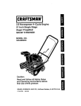
49.2cc 2-cycle
2.0HP 10 Inch Tines
CULTIVATOR
MODEL NO.
536.292521
Caution:
Read and follow all Safety Rules
and Operating Instructions before
first use of this product.
SEARS,
F-001300M
ROEBUCK
AND CO., Hoffman
Estates,
IL 60179 U.S.A.
TABLE OF CONTENTS
WARRANTY STATEMENT .....
SAFETY RULES ..............
INTERNATIONAL SYMBOLS,,.
ASSEMBLY ..................
OPERATION
.................
MAINTENANCE
..............
2
3
5
6
8
13
WARRANTY
LIMITED
ONE-YEAR
WARRANTY
SERVICE AND ADJUSTMENT
..
16
TROUBLE SHOOTING CHART.,
19
REPAIR PARTS ...............
20
ENGINE REPAIR PARTS .......
25
SPANISH (ESPAI_IOL) ..........
31
PARTS ORDERING/SERVICE
..
BACK COVER
STATEMENT
ON CRAFTSMAN
CULTIVATOR
For one year from the date of purchase, when this Craftsman Cultivator is maintained, lubricated, and tuned up according to the operating and maintenance instructions in the owner's
manual, Sears will repair, free of charge, any defect in material or workmanship.
This warranty excludes tiRe(s), spark plug, and air cteaner which are expendable parts and
become worn during normal use.
If this Craftsman Cultivator is used for commercial or rental purposes, this warranty applies
for onIy 90 days from the date of purchase.
WARRANTY SERVICE IS AVAILABLE BY RETURNING THE CRAFTSMAN CULTIVATOR TO THE NEAREST SEARS SERVICE CENTER/DEPARTMENT
IN THE UNITED
STATES. THIS WARRANTY APPLIES ONLY WHILE THIS PRODUCT IS IN USE IN THE
UNITED STATES.
This warranty gives you specific legal rights, and you may also have other rights which may
vary from state to state.
Sears, Roebuck and Co., D817WA, Hoftman Estates. IL 60179
IMPORTANT: This unit is equipped with an internal combustion engine and must not be
used on or near any unimproved forest-covered,
brush-covered or grass-covered
land
unless the engine's exhaust system is equipped with a spark attester meeting
applicable local or state laws (if any). If a spark attester is used, it must be maintained in
effective working order by the operator.
In the State of California the above is required by iaw (Section 4442 of the California
Public Resources Code). Other states may have similar laws. Federal laws apply on federal lands. See a Sears Authorized Service Center for a spark arrester for the muffler.
F=001300M
2
IMPORTANT
Safe Operation
Practices
for Cultivator
WARNING:
It means'. "Attention!
Look for this
Become
symbol
Alert.
to point
Your out
Safety
important
|s Involved.
safety precautions.
_IL
ARNING: To prevent accidental starting when setting-up,
transporting, adjusting or making repairs, always disconnect spark
plug wire and put wire where it cannot
contact the spark plug.
IMPORTANT: Safety standards require operator presence contro% to minimize the risk of injury. Your cultivator is equipped with such
controls. Do not attempt to defeat the function
of the operator presence control under any circumstances.
Before Use
• Read the owner's manual carefully. Be
thoroughly familiar with the controls and
the proper use of the cultivator. Know how
to stop the cultivator and disengage the
controls quickly.
•
Do not operate the cultivator without wearing adequate outer garments. Wear footwear that wiil improve footing on slippery
surfaces.
• Keep the area of operation dear of al persons, particulady small children and pets.
• Thoroughly inspect the area where the cultivator is to be used and remove all foreign
objects.
Fuel Safety
• Handle fuel with care; it is highly flammable.
•
Use an approved container.
• Check fuel supply before each use, allowing space for expansion as the heat of the
engine and/or sun can cause rue} to expand.
• Fill fuel tank outdoors with extreme care.
Never fill fuel tank indoors. Replace fuel
tank cap securely and wipe up spilled fuel.
• Never remove the fuel tank cap or add fuel
to a running or hot engine.
F_O01300M
• Never store fuel or cultivator with fuel in the
tank inside a building where fumes may
reach an open flame.
Operating
Safety
• Never allow children or young teenagers to
operate the cultivator. Keep them away
while it is operating. Never allow adults to
operate the cultivator without proper instruction.
• Do not operate this machine if you are taking drugs or other medication which can
cause drowsiness or affect your abi{ity to
operate this machine.
• Do not use this machine if you ate mentally
or physically unable to operate this machine safely.
• Always wear safety glasses or eye shields
during operation or while performing an
adjustment or repair to protect your eyes
from foreign objects that may be thrown
from the cultivator.
• Do not put hands or feet near or under rotating parts.
• Exercise extreme caution when operating
on or crossing gravel drives, walks, or
roads. Stay alert for hidden hazards or
traffic.
• Esercise caution to avoid slipping or falling.
• Never operate the cultivator without proper
guards, plates, or other safety protective
devices in place.
• Never operate the cultivator at high transport speeds on slippery surfaces. Look behind and use care when backing.
• Never allow bystanders near the cultivator.
• Keep children and pets away while
operating.
• Never operate the cultivator without good
visibility or Iight.
• Do not run the engine indoors. The exhaust fumes are dangerous, containing
CARBON MONOXIDE, an ODORLESS
and DEADLY GAS.
IMPORTANT
• Take all possible precautions when leaving
the cultivator unattended. Stop the engine,
and keep the wire away from the plug to
prevent accidental starting. Thoroughly in-
,
spect the cultivator for any damage, and
repair the damage before restarting and
operating it.
Do not overload the cultivator capacity by
attempting to till too deep at too fast a rate.
If cultivator should start to vibrate abnormally, stop engine and check immediately
for the cause. Vibration is generally a warning of trouble.
Safe Storage
• Always refer to the owner's manual instructions for important details if the cultivator is
to be stored for an extended period.
•
Never store the cultivator with fuel in the
Stop the engine whenever you leave the
operating position. Also, disconnect the
spark plug wire before unclogging the tines
and when making any repairs, adjustments, or inspections.
fuel tank inside a building where ignition
sources are present such as water and
space heaters, clothes dryers, and the like.
Allow the engine to cool before storing in
any enclosure.
•
Keep the cultivator in safe working condition. Check all fasteners at frequent intervals for proper tightness.
Repair
/ Adjustments
When cleaning, repairing, or inspecting,
shut offthe engine and make certain all
moving parts have stopped.
Never attempt to make any adjustments
while the engine is running except when
specifically recommended by the manufacturer
Safety
• After striking a foreign object, stop the engine. Remove the wire from the spark plug,
F=001300M
4
IMPORTANT
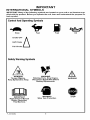
INTERNATIONAL SYMBOLS
IMPORTANT: Many of the following symbols are located on your unit or on literature supplied with the product. Before you operate the unit, learn and understand the purpose for
each symbol.
Control And Operating Symbols
Slow
Fast
Fuel
Oil
Half Choke
Choke OFF A
Full Choke
Safety Warning Symbols
WARNING
Thrown Objects.
Keep Bystanders Away.
IMPORTANT
Read Owner's Manual
Before Operating
This Machine.
F-OO1300M
WARNING
Rotating Parts. Stop Engine.
Disconnect Spark Wire Before
Making Adjustments.
Wear
WARNING
Eye Protection
5
WARNING
STOP
ASSEMBLY
ASSEMBLY
PARTS PACKED SEPARATELY
IN CARTON
1 - Owner's Manual (not shown)
1 - 5.2 oz. 2-cycle Oil
f - 5.2 oz. 2-cycle
Oil
glasses
or eye
shields
while
asWARNING:
Always
wear
safety
sembling the cultivator.
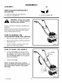
Figure 1 shows the cultivator completely assembled.
References to the right or left side of the cultivator are from the viewpoint of the operatot's position behind the unit.
HOW TO REMOVE THE
CULTIVATOR
FROM THE CARTON
1. Removethe bottle of oil from the carton.
2.
Remove the packing material positioned
around the unit.
3.
Lift the cultivator out of the carton and
place on a hard level surface.
Figure 1
HOW TO RAISE THE HANDLE
1.
2.
Loosen the knobs (see Figure 2). Tilt
the cultivator forward and rotate the upper handle to the upright position. Make
sure the throttle cable is not caught between the handles.
Handle
Knobs
Tighten the knobs.
NOTE: To tighten the knobs, hold the
curved carriage bolt head against the outside of the lower handle as you tighten
the knobs.
Figure 2
F=001300M
6
ASSEMBLY
_." CHECKLIST
For the best performance and satisfaction
from this quality product, please review the
following checklist before you operate the
cultivator:
v"
All assembly instructions
completed.
have been
v"
Check carton. Make sure no loose
parts remain in the carton.
v"
All fasteners have been properly tightened.
As you learn how to use the cultivator', pay
extra attention to the following important
items:
v'_"
Fuel tank is filled with a fresh, clean,
fuel mixture.
v'_"
Become familiar and understand the
function of all controls. Before you
start the engine, operate all controls.
F=001300M
7
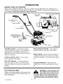
OPERATION
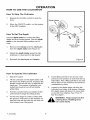
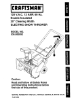
KNOW YOUR CULTIVATOR
READ THE OWNER'S
MANUAL AND ALL SAFETY RULES BEFORE YOU OPERATE the
cultivator. To familiarize yourself with the Iocation of the controls, compare the illustrations with
our cultivator'. Save this manual for future reference.
ON / OFF
Switch
Recoil Starter Handle
/
Throttle Control
Lever
Upper Handle
Lower Handle
Choke Control
Fuel Cap
Tine Shield
Assembly_
Tines
Figure 3
Throttle
Control
i Controls the engine
speed and the tine rotation. The cultivator is
Recoil Starter Handle - The engine is
equipped with an easy pull recoil starter.
equipped with a centrifugal clutch that engages the tine drive system when the engine
speed is increased.
Depth
Choke Control Lever - Use to assist
when starting a cold engine.
to adjust the depth of cut. Also use to help
control the direction and speed of the cultivator.
Switch
- Mount with the wheels up
- The ON position al-
lows the engine to start. The OFF position
stops the engine and keeps the engine from
starting.
Transport
Wheels
Mount with the
wheels down when transporting the cultivator.
i
ON / OFF
Stake
EYE PROTECTION
Always wear safety glasses. If you wear eye
glasses, put a Wide Vision Safety Mask over
your eye glasses.
F-001300M
the cultivator can result in forWARNING: Debris thrown from
eign objects being thrown into
the eyes, which can cause severe eye
damage. Always wear safety glasses or
eye shields when operating the cultivator.
OPERATION
HOW TO USE THE CULTIVATOR
How To Stop The Cultivator
1.
2.
Release the throttle control to stop the
tines.
Depth Stake
Move the ON/OFF switch, on the engine,
to the OFF position.
Clevis Pin
How To Set The Depth
Use the depth stake to control the tilling
depth and the forward speed. Set the depth
stake to the desired tilling position as follows:
1.
Remove the hairpin and the clevis pin
from the depth stake (see Figure 4).
2.
Adjust the depth stake upward to dig
shallower or downward to dig deeper.
3.
Reinstall the clevis pin and hairpin.
Depth Stake
Bracket
Figure 4
How To Operate The Cultivator
1.
Start the engine.
5.
2.
Tilt the unit back on the depth stake until
the tines are offthe ground. Squeeze the
throttle control all the way up against the
hand grip. The engine is governor controlled and must be run at full throttle
Avoid tilling soil that is too dry as it will
pulverize and produce a dust that will not
hold water'. Also, tilling soil that is too wet
will be hard on the machine and produce
unsatisfactory clods.
6.
Lowering
cultivator
the depth
er and till
while tilling.
3.
Hold the handle firmly and slowly tilt the
unit forward to begin the tilling action.
4.
As the tines begin to make contact with
the ground, hold back on the handles so
that the tines will dig into the soiI and not
ride forward over the ground.
F-001300M
the depth stake will slow the
and make it till deeper'. Raising
stake will allow it to move fastmore shallow. See "How To
Set The Depth".
_
9
ARNING: Keep away from the
rotating tines. Rotating tines
can cause injury.
OPERATION
BEFORE STARTING THE ENGINE
How To Prepare
A
_when
The
IMPORTANT: Do not use outboard mo-
Engine
tor oil or multi-viscosity
10W-30 or 10W-40.
WARNING: Always use a safety
fuel container. Do not smoke
adding the fuel mixture to
the engine. When inside an enclosure,
do not fill the fuel tank. Before you add
the fuel mixture, stop the engine. Let the
engine cool for several minutes.
3.
install the fuel cap onto the gasoline container. Vigorously shake the gasoline
container to mix the oil with the gasoline.
4.
Add an additional three (3) U.S. quarts of
gasoline to the gallon container. Again
shake the gasoline container.
5.
This completes the gasoline mixing procedure. The gasoline can now be added
to the fuel tank.
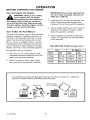
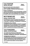
How To Mix The Fuel Mixture
The two cycle engine, used on this cultivator,
requires a mixture of gasoline and oil for lubrication of the bearings and other moving
parts. The correct fuel mixture ratio is 24:1
(5.2 oz. oil per one gallon of gas - see the
Fuel Mixture Chart). Gasoline and oil must
be pre-mixed in a clean gasoline container.
Always use fresh, clean, unleaded gasoline.
oils,such as
FUEL MIXTURE CHART (mixture
U.S.
Mix gasoline and oil as follows:
1. Pour one (1) U.S. quart of fresh, clean,
unleaded automotive gasoline into a one
gallon size gasoline container.
2. Add 5.3 ounces of clean, high quality,
two-cycle oil to the gasoline container.
24:1)
Sl. (Metric
GAS
OIL
GAS
OIL
1 Gal.
5.2 oz.
4 Liters
.167 L
2 Gal.
11 oz.
8 Liters
.333 L
5 Gal.
27 oz.
20 Liters
.833 L
Do not fill the fuel tank with gasoline that does not have oil mixed in it. Shake the
gasoline container before each filling of the fuel tank.
Ol,
(5.2 ozI
Add more gas
(3 U. S. Quarts)
Shake Can
+
+
1 U.S. Gallon container '_
F-001300M
10
/
OPERATION
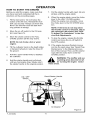
HOW TO START THE ENGINE
Before you start the engine, make sure that
you have read and understand all the instructions on the preceding pages.
1.
7.
Pull the starter handle with rapid, full arm
strokes until the engine starts.
8.
When the engine starts, move the choke
Iever to the HALF CHOKE position.
When the engine runs smoothly, move
the choke lever to the NO CHOKE position.
Fill the fuel tank to 1/2 inch below the
bottom of the fill neck. Reinstall the fuel
tank cap securely. AIways use fresh fuel.
Never use fuel that could be stale from
iong periods of storage.
2.
Move the on-off switch to the ON position (see Figure 5).
3.
Move the choke controI to the FULL
CHOKE position (ali the way down).
NOTE: If the tines do not stop when
the throttle control is released, adjust
the carburetor idle speed. See "How
To Adjust The Carburetor" in the Service And Adjustments.
g.
NOTE: Do not choke a hot or warm
engine.
4.
the OFF position.
10. If the engine becomes flooded remove
and dry the spark plug. See "Spark Plug
Maintenance" in the Maintenance sec-
Tilt the cultivator back on the depth stake
or transport wheels to raise the tines off
the ground.
5.
Hold the upper handle firmly to stabiiize
the cultivator.
6.
Hold the starter handle and pull slowly
until you feel engine drag. Slowly return
the starter handle to the original position.
ON / OFF
Switch
To stop the engine, release the throttle
control and move the on-off switch to
tion of this manual. Then, pull the starter
rope with the choke lever in the NO
CHOKE position.
rounding
hot surafWARNING: areas
The become
muffler and
ter running the engine. Avoid
these areas.
Recoil Starter Handle
Air Cleaner
Figure 5
F-001300M
11
OPERATION
CULTIVATING TIPS
Tilling is digging in, turning over and
breaking up packed soil before planting.
Loose unpacked soil helps root growth.
Best tilling depth is 4 to 6 inches. A tiller
wiII also clear the soil of unwanted vegetation. The decomposition of this vegetation matter enriches the soil. Depending
on the climate (rainfall and wind), it may
be advisable to tilI the soil at the end of
If the cultivator stops forward motion and
tries to dig deeper than necessary, move
the handles from side to side to start forward motion.
Cultivating is loosening or digging
around growing plants which allows the
plants to flourish.
the growing season to further condition
the soil.
When using the cultivator to remove
weeds, it is best to cultivate no deeper
than 1-1/2 inches. Cultivating deeper will
only pull to the surface ungerminated
weed seeds. Raising the depth stake wilI
allow it to move faster and till more shallow.
Avoid tilling soil that is too dry as it will
pulverize and produce a dust that will not
hold water. Also, tilling soil that is too wet
will be hard on the machine and produce
unsatisfactory clods.
When cultivating around piants or close
areas, you may want to remove the outside tines. See "Tine Replacement" in
the Service/Adjustments
section.
Better growth will be obtained if an area
is tilled properly and used soon after tilling to preserve the moisture content.
The depth stake (on the back of the cultivato o serves a dual purpose. It helps
regulate the depth of the cut and also
acts as a brake to help the operator control the speed of the cultivator.
manual. Know location and
WARNING: Read the Owner's
functions of all controls. Keep
all safety devices and shields in place.
Never allow children or uninstructed
Lowering
cultivator
the depth
er and till
adults to operate cultivator. Shut off engine before unclogging tines or making
repairs. Keep bystanders away from machine. Keep away from rotating parts
and tines. They can cause injury.
F-OO1300M
the depth stake will slow the
and make it till deeper'. Raising
stake will allow it to move fastmore shallow.
12
MAINTENANCE
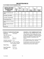
CUSTOMER RESPONSIBILITIES
SERVICE RECORDS
Fill in dates as you
complete regular
service.
After
Before First Every
Each
2
25
Use Hours Hours
Tighten AI] Screws and
Nuts
I
I
N/
Every
Before
75
Before Each SERVICE
Hours Storage Season DATES
I
....
N/
I
I
I
Lubricate Tine Shaft
Check Spark Plug
Clean and Oil Air Cleaner
Filter
I
'
•
'
N
I
i
_]
•
i
•
Clean Cylinder Exhaust
Ports
Drain Fuel
"
"
"
"
PRODUCT SPECIFICATIONS
Model No.:
536.292521
2
Displacement:
3.0 cu. in.
(49.2 cc.)
Gasoline Capacity:
20 oz.
Champion
RCJ-6Y
Spark Plug Gap:
0.035 inch
Idle RPM:
1700-3000
F-OO1300M
"
"
The warranty on this cultivator does not cover items that have been subjected to operator abuse or negligence. To receive full value
from the warranty, the operator must maintain the cultivator as instructed in this
manual.
Some adjustments must be made periodically to properly maintain your cultivator.
Fuel/Oil Mix Ratio:
24:1 Oil To Gas
(5.3 oz. oil to 1 gal. gas
(use unleaded regular)
Spark Plug:
_/
GENERAL RECOMMENDATIONS
Date Of Purchase:
Horse Power:
"
All adjustments in the Service and Adjustments section of this manual must be
checked at least once each season.
13
MAINTENANCE
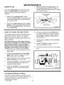
LUBRICATION
Every 25 hours and/or at the beginning of
each season, make sure the gear box is
filled with lubricant (see Figure 6). Tubes of
gear lubricant are available from most automotive supply stores. Use portable tool
grease such as Lubriplate 630AA (Product
No. 06787, 1-3/4 oz. tube) or Lubdplate
GR-132 (Product No. 15892, 10 oz. tube).
if it is damaged (see the Repair Parts
section in this manual).
6.
Clean and lubricate the tine shaft with a
few drops of oil.
7.
Reinstall the left side tines.
8.
Remove the right side tines. Check the
felt washer for damage. Clean and oil
the tine shaft. Reinstall the right side
tines.
After cleaning and before storage, apply oil
to the tine shaft (see Figure 6).
_1_
Air Vent Screw
sion
to coolAllow
beforethe
filling
with
ARNING:
transmisgrease.
-%
1.
Remove both left side tines. See "How
To Replace The Tines" in the Service
and Adjustments section.
2.
Remove the air vent screw (see
Figure 6).
3.
Mount a grease gun onto the grease fitting. Fill the transmission until the
grease begins to come out of the air vent
screw hole.
4.
Reinstall the air vent screw.
5.
Check the condition of the felt washer
Grease Fitting
Figure 6
(see Figure 6). Replace the felt washer
HOW TO CLEAN THE TINES
5.
Always remove dirt and debris from the cultivator after each use. Remove any string,
wire or vegetation that may become lodged
in the mechanism and stop the tines from
rotating.
f.
Connect the spark plug wire to the spark
plug.
Release the throttle control and move
the on-off switch to the OFF position.
Disconnect the spark plug wire from the
spark plug.
2.
While wearing gloves, remove the hairpins and clevis pins that secure the tine
assemblies to the shaft (see Figure 7).
Remove the tines from the shaft.
3.
Remove any lodged debris from the
shaft and tines. Clean and lubricate the
tine shaft with a few drops of oil.
4.
Reassemble
Hair Pins
the tines on the shaft and
secure with a clevis pin and hairpin.
F_001300M
14
Tines
Figure 7
MAINTENANCE
SPARK PLUG
3.
Check the spark plug every 25 hours. Replace the spark plug if the electrodes are
pitted or burned or if the porcelain is
cracked.
1.
Make sure the spark plug is clean.
Clean the spark plug by carefully scraping the electrodes (do not sand blast or
use a wire brush).
2.
Check the spark plug gap with a feeler
gauge. See "Product Specifications" for
the correct spark plug gap and replacement spark plug.
Feeler Gauge
0.035"
Spark Plug
Figure 8
HOW TO CLEAN THE AIR FILTER
6.
filter every 25 hours. Clean more often in
dusty conditions. Remove and clean the air
filter as follows:
any excess oil.
7.
2.
Remove the screws from the air filter
cover (see Figure 9). Remove the air
filter cover and the air filter.
3.
Wipe the cover and the inside of the air
filter housing with a clean cloth.
4.
Clean the air filter in a solution of water
Put the clean air filter into the air filter
housing.
CAUTION: Never run the engine without
the air filter installed. An air filter clogged
with dust can result in loss of engine
power and can cause excessive wear or
damage to the engine. If the air filter is
clogged, clean or replace immediately.
Disconnect the spark plug wire from the
spark plug.
Cover the outside of the air filter with
oil. Use the same type of oil as used to
make the fuel mixture. Lightly squeeze
the air filter to distribute and remove
The engine uses a foam air filter that can be
cleaned and reused. Clean and oil the air
1.
Before installing the spark plug, coat
the threads lightly with oil for easy removal. Tighten the spark ptug to a torque
of 15 foot-pounds.
8.
Install the air filter cover and secure
with the screws as shown.
9.
Connect the spark plug wire to the spark
plug.
Air Fiiter
and household detergent. Rinse thoroughtly in clean water.
5.
Screw
Filter Housing
Wrap the air filter in a dry clean cloth.
Squeeze out (do not twist) all solution
until dry.
CYLINDER
EXHAUST
Figure 9
PORTS
Clean the cylinder exhaust ports after every
75 hours of operation. For this procedure, we
recommend that you take your unit to a
Sears Service Center.
F-001300M
15
SERVICE AND ADJUSTMENT
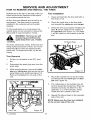
HOW TO REMOVE AND INSTALL THE TINES
Tine Installation
References to the right or left side of the cultivator are from the viewpoint of the operator's position behind the unit.
1.
Clean and lubricate the tine shaft with a
few drops of oil.
All four tines are different and cannot be in2.
terchanged. The tines must be correctly
installed or the cultivator will not function
propedy.
Place the inside tine on the tine shaft
and reinstall the clevis
3.
To till around plants or in small areas, the
outside tines can be removed to reduce the
tilIing width to approximately 7 inches.
pin and hairpin.
When the tines are properly installed, the
Ietter R will be visible on the outside of
the right tine (see Figure 11). The letter
L will be visible on the outside of the left
tine.
sharpening and will become
WARNING: The tines are self
quite sharp from use. Handle
carefully.
Oil Drain Plug
The tines will all wear evenly. If the tines are
being replaced because of wear, we recommend that all four tines be replaced at the
same time. To replace the tines, do the following:
Tine Removal
1.
Put the on-off switch in the OFF position.
2.
Disconnect the spark plug wire from the
spark plug.
3.
While wearing gloves, remove the hairpins and clevis pins that secure the tine
assemblies to the shaft (see Figure 10).
Remove the tines from one side of the
unit.
,4
r_
4.
_- "_mP'-,_,Figure 11
Mount the outside tine on the tine shaft
and fasten with the clevis pin and hairpin (see Figure 10).
5.
The cutting tips on the outside tines all
bend in toward the inside tine. When assembled correctly, the letter R on the
right side, or L on the left side, will be
visible from the outside of the unit.
6.
Repeat the above steps on the opposite
side of the unit.
NOTE: Make sure the tines are installed
on the correct side of the unit.
Hair Pins
F-001300M
Tines
Figure 10
16
SERVICE AND ADJUSTMENT
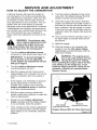
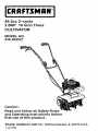
HOW TO ADJUST THE CARBURETOR
A dirty air cleaner will cause the engine to
run improperly or to smoke excessively. Before adjusting the carburetor, make sure the
air cleaner is dean. Never make unnecessary adjustments to the carburetor'. The carburetor was set at the factory to operate
efficiently under most applications. However,
if adjustments are required, we recommend
you contact your nearest Sears Service Center. If you feel that you are competent to
make carburetor adjustment proceed as foIlows.
8.
Turn the mixture adjusting screw clockwise until it is halfway between the first
_osition and the second position.
9.
Check the engine idle speed. Start the
engine and release the throttle control. If
the tines do not turn with the throttle controI is released, the idle speed is correct.
If the tines turn with the throttle control is
released, adjust the engine idle speed as
follows.
10. Have someone tilt the cultivator back on
its depth stake so that the tines are off
the ground.
when
makingUse
adjustments
that
WARNING:
extreme care
require the engine to be running. Keep hands, feet, hair and loose
clothing away from all moving parts.
_lb
11. Start the engine.
1.
12. With the throttle in the released (idle
position), turn the idle speed adjustment screw counterclockwise until the
tines stop rotating.
Turn the mixture adjustment screw
clockwise to until closed (see Figure 12).
IMPORTANT: To prevent damage to
the carburetor or to the adjusting
screw, tighten the adjustment screws
with your fingers.
2.
Turn the mixture adjustment
counterclockwise one turn.
3.
Start the engine and let it warm up for
approximately 3 to 5 minutes. Do not adjust the carburetor when the engine is
cold.
4.
If the engine runs erratically or stops after the choke lever is moved to the
nor
is set atThe
the engine
factory. goverDo not
WARNING:
change the governor setting.
Over speeding the engine above the factory setting can be dangerous. If you
think the engine governor needs an adjustment, contact your nearest Sears
Service Center.
_lb
screw
CHOKE OFF position, then open the
mixture adjustment screw an additional 1/8 turn counterclockwise.
5.
With the engine running, release the
throttle control (idle position) to make the
mixture adjustments.
6.
Slowly turn the mixture adjustment
screw clockwise until the engine begins
to run erratically. Note this position.
7.
Idle Speed
Adjustment Screw
Then, slowly turn the mixture adjustment
screw countercIockwise until the engine
again begins to run erraticaliy. Note this
position.
F-001300M
Mixture
Adjustment Screw
Engine Shown With Air Filter Removed
Figure 12
17
SERVICE AND ADJUSTMENT
STORAGE
Cover the cultivator with a suitable protective cover that does not retain mois-
tivator indoors with fuel in the
ARNING: Never store the culfuel tank. Never store in an en-
_lb
ture. Do not use plastic.
closed, poorly ventilated area where
fumes could reach an open flame, a
spark or a pilot light as on a furnace, water heater or clothes dryer.
IMPORTANT: Never cover the cultivator
while the engine and exhaust areas are
still warm.
NOTE: A yearly checkup or tune-up by a
Sears Service Center is a good way to
make sure that your cultivator will provide maximum performance
for the next
season.
oline
while inside
building,gasARNING:
Do nota remove
near a fire, or while you smoke.
Gasoline fumes can cause an explosion
or a fire.
_lb
When the cultivator is put in storage for thirty
days or more, follow the steps below to
make sure the cultivator is in good condition
the following season.
Engine
IMPORTANT: It is important to prevent
gum deposits from forming in fuel system
parts such as the carburetor, fuel filter,
fuel hose, and tank during storage. Also,
using alcohol-blended
fuels (called gasohol, ethanol or methanol) can attract
moisture which leads to separation and
formation of acids during storage. Acidic
gas can damage the fuel system of an engine while in storage.
Cultivator
Completely dean the cultivator.
Remove the tines. Clean and apply oil to
the tine shafts. Mount the tines onto the
tine shafts. See "How To Remove And
Install The Tines" in the Service And Adjustments section.
To prevent engine damage when the cultivator is in storage for 30 days or more, follow
the steps below:
Loosen the knobs that secure the upper
handle to the lower handle. Carefully fold
the upper handle. Make sure the throttle
cable is not bent. Tighten the knobs.
Let the engine run until it is out of gasoline.
The cross piece of the upper handle (between the lower handles) can now be
used as a carry handle. To store the cultivator up off the floor and out of the way,
the cross piece can also be hooked over
a wall hook.
Slowly pull the starter handle until you
feel resistance due to compression in
the cylinder, then stop.
Slowly release the starter rope. This
position will close both the intake and the
exhaust ports and help prevent corrosion
of the piston and cylinder.
Put the cultivator in a building that has
good ventilation.
F-OO1300M
18
TROUBLE
SHOOTING
CHART
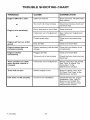
TROUBLE
CAUSE
CORRECTION
Engine difficult to start
Stale fuel mixture
Drain fuel tank. FilI with fi'esh
fuel mixture.
Too much oil in fuel mixture
Check fuel mixture chart and
mix fresh fuel.
Dirt in fuel tank or out of fuel
Clean fuel tank.
Carburetor out of adjustment
See Carburetor Adjustment
section.
Fouled spark plug
Clean and set spark plug
gap.
Engine will not run at full
speed
Dirty air filter
Clean and oil air filter.
Engine speed does not
increase properly
Debris interfering with throttle
linkage
Clean dirt and debris of top
of carburetor.
Engine smokes
excessively
Plugged air filter
Clean and oil air filter.
Too much oil in fuel mixture
Check fuel mix chart and mix
fresh fuel.
Tines continue to rotate
when throttle control is
released
Carburetor out of adjustment
Adjust carburetor idle speed.
See "How To Adjust The
Carburetor" in the
Maintenance section.
Tines will not turn
Debris lodged in tine
Remove debris. See "How
To Clean The Tines" in the
Maintenance section.
Unit does not till properly
Incorrect tine instalIation
Check the tines for proper
installation. See "How To
Remove And Install The
Tines" in the Service And
Adjustments section.
or
Engine runs erratically
or
F=001300M
19
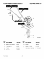
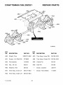
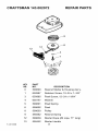
CRAFTSMAN
536.292521
REPAIR PARTS
10
323392C
KEY
NO. DESCRIPTION
KEY
NO. DESCRIPTION
PARTNO.
PARTNO.
10
Engine 143.002072
2.0HP
14
Screw
180042
11
Flat washer
56694
17
Cable, Throttle
319306
12
Rotor
335350
--
Instruction Manual
F-OO1300M
13
Washer
120380
F=OO1300M
20
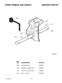
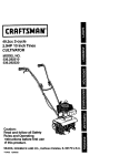
CRAFTSMAN
536.292521
REPAIR PARTS
310
300
318848C
F-OO1300M
KEY
NO.
DESCRIPTION
PARTNO.
300
Transmission
740061
310
Bracket, Depth Rod
340550
311
Screw, 1/4-20xl.25
180024
312
Nut, 1/4-20
782585
21
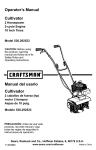
CRAFTSMAN
536.292521
REPAIR PARTS
482
4814_
496
496
318849c
KEY
NO. DESCRIPTION
PARTNO.
309073-848
493
Tine Assy. Inner RH
56156_53
273869
494
Tine Assy. Outer RH
56154-853
Flat washer
120392
495
Clevis Pin
56123
483
Nut,
46931
496
Hair Pin
56180
490
Washer,
56158
--
Decal, Caution
320711
491
Tine Assy.
Inner
LH
56157-853
--
Decal, Tine Shield
712457
492
Tine Assy.
Outer
LH
56155_53
KEY
NO.
DESCRIPTION
480
Shield,
Tine
481
Screw,
1/4-20x5.00
482
F=001300M
PART NO.
1/4-20
Felt
22
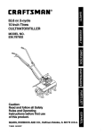
CRAFTSMAN
536.292521
REPAIR PARTS
66O
J
662
661
663
318852G
F=OO1300M
KEY
NO.
DESCRIPTION
PARTNO.
650
Wheel Support Assy.
330799-853
660
Clevis Pin
333635
661
Hair Pin
56180
662
Tire & Rim
339277
663
Push On Nut
73664
23
CRAFTSMAN
536.292521
REPAIR PARTS
947
930
[5
944
932
941
934
319375C
F=001300M
KEY
NO.
DESCRIPTION
PARTNO.
930
Upper Handle
56237-853
932
Lower Handle LH
339398-853
934
Lower Handle RH
339399-853
941
Bolt 5/16-18xl
56199
942
Formed Washer
943
Flat washer
120393
944
T Knob
57171
945
Nut, 5116-18
120376
946
Hand Grip
56778
947
Screw, 10-16xl.50
426635
948
Cable Tie
712267
--
Decal, Caution (Starting)
24
305828
.63
783000
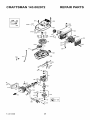
CRAFTSMAN
143.002072
REPAIR PARTS
7250
243
101\
331
110 f
_210
184
177
_/178
F-OO1300M
25
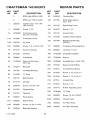
CRAFTSMAN
KEY
NO.
1
PART
NO,
143.002072
REPAIR PARTS
DESCRIPTION
KEY
NO.
PART
NO.
0
RPM High 5000 to 5400
93
650849
Flywheel Nut
0
RPM Low 1700 to 3000
100
611056
Solid State Ignition
(Incl. 101)
250303
Cylinder(Incl.
187 & 187A)
101
610118
Spark Plug Cover
DESCRIPTION
119, 184,
3
650888
Screw, T-30
103
651007
Screw, T-15
13
270288A
Crankcase Ass'y.
(incl. 20, 44 & 69)
110
611135
Ground Wire
119
510349
Cylinder Head Gasket
13A
270298
Crankcase
135
611049
16B
490324
Air Vane
Resistor Spark Plug
(RCJ8Y)
16C
650986
Screw, T-8, 3-48 x 7/32"
177
650858
Carburetor
19
570716
Governor Spring
178
650580
Lock Nut, 10-24
20
510328
Oil Seal
184
510327B
Carburetor Gasket
30
290664
Crankshaft
187
570648A
Spacer
39
310285A
Piston & Rod Assy.
(Incl. 42)
187A
570698A
Air Baffle (incl. 184 & 187)
200
570700
Speed Control Body
42
310275
Ring Set
203
570701
Compression
44
530163
Cartridge
204
651042
Screw, T-15, 8-32 x 1"
69
510348
"Q" Ring
209
651042
Screw, T-15, 8-32 x 1"
77
530110
Ball Bearing
210
27793
Conduit Clip
78
510319
Oil Seal
211
651047
Screw, T-15
79
650844
Screw, 1/4_20 x 3/4"
216
570712
R.RM. Adjusting Lever
89
611054
Flywheel Key
230
570649A
"Q" Ring
90
611180
Flywheel
243
650955
Screw, 10=32 x 29/32"
91
590691
Pawl Spring
243A
650964
Thread Insert
91A
590692
Starter Pawl
245
450252
Air Filter (Poly)
91B
650985
Screw, 12-24 x 11/64"
245A
450255
Air Filter (Flocked)
92
650848
Belleville Washer
F-001300M
Cover
Mounting Stud
Spring
Bearing
26
CRAFTSMAN
143.002072
REPAIR PARTS
250
450253
Air Cleaner Cover
301
410280
Fuei Cap
257
650867
Screw, 10-24 x 1/2"
326
570659
Blower Housing Plug
258
350435
Blower Housing Base
331
610650B
Toggle Switch
261
650850
Screw, 8-32 x 1-9/16"
370C
550239
Choke Decal
262
650939
Stud
370D
35977
Caution Decal
274
510347
Exhaust Gasket
370G
550228
Instruction Decai
275
390322
Muffler (incl. 274 & 277)
370Q
550247
Emissions
277
650938
Screw, 1/4-20 x 2.409"
380
640231
Carburetor (Incl. 184)
290
410246A
Fuel Line
391
590690
Recoil Starter Ass'y.
292
410253
Fuel Line Clamp
520
0
Clutch (Supplied by OEM)
297
27261
Washer
900
0
298
650954
Lock Nut, 8-32
Replacement Engine
710580, order from
71-999
300
410277A
FuelTank (Incl. 290, 292,
298, 301 & 3700)
900
0
Replacement S/B
710542B, order from
71-999
F-OO1300M
27
Decal
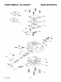
CRAFTSMAN
143.002072
60
REPAIR PARTS
_-'_.
152
iS0
F-OO1300M
28
CRAFTSMAN
KEY
NO.
F-OO1300M
143.002072
REPAIR PARTS
PART
NO.
DESCRIPTION
o
640231
Carburetor" (Incl. 184 of Engine Parts List)
1
640232
Throttle Shaft & Lever Ass'y.
2
640233
Throttle Return Spring
3
640234
Dust Seal Retainer
3B
640236
Spacer
4
640237
Dust Seal Washer
5
640238
Dust Seal
6
640239
Throttle Shutter
7
640235
Screw, Throttle Shutter & Dust Seal Retainer
17
640240
Idle Speed Screw
27
640241
Hinge Pin
28
640242
Metering Lever
30
640243
Inlet Needle
31
640244
Metering Lever Spring
34
640245
Screw, Metering Lever Pin
4O
640246
High Speed Jet
40A
640247
High Speed Jet Sealer Cap
50
640248
Diaphragm (Included in Gasket Set)
51
640249
Cover Gasket (Included in Gasket Set)
52
640250
Cover
53
640251
Cover Screw
60
640256
Repair kit (Incl. Items Marked PK in Notes)
Incl. (I) each of part #'s 640242, 640243,
640257
62
640252
Pump Diaphragm (Incl. in Gasket Set)
63
640253
Pump Gasket (Included in Gasket Set)
64
640255
Pump Cover
65
640254
Pump Cover Screw
70
640257
Gasket Set Incl. (1) each of part #'s 640248,
640249, 640252, 640253
29
CRAFTSMAN
143.002072
13
F-001300M
REPAIR PARTS
12
KEY
NO.
0
PART
NO.
590690
Rewind Starter & Housing Ass'y.
1
650987
Retainer Screw, 10-24 x 1-3/8"
3
650985
Pawl Screw, 12-24 x 11/64"
4
650147
Washer
5
590691
Pawl Spring
6
590692
Pawl
8
590693
Pulley
9
590562
Rewind Spring
12
590639
Starter Rope (#4 rope, 71" long)
13
590452
Starter Handle
30
DESCRIPTION
For the repair or replacement
parts you
need delivered directly to your home
Call 7am-7pm,
7days a week
1-800-366-PART
(1-800-366-7278)
Para ordenar piezas con entrega
a domicilio - 1-800-659-7084
For in-house major brand repair service
Call 24 hours a day, 7days a week
1-800-4-REPAIR
(1-800-473-7247)
Para pedir servicio de reparacibn
domicilio1-800-676-5811
a
For the location of a Sears Parts and
Repair Center in your area
Call 24 hours a day, 7days a week
gggggg
1-800-488-1222
For information on purchasing a Sears
Maintenance agreement or to inquire
about an existing Agreement
Call 9am-5pm,
Monday-Saturday
1-800-827-6655
When requesting service
parts, always provide the
mation:
• Product Type
• Part
• Model Number
• Part
or ordering
following inforNumber
Description
America's
Repair
Specialists
Printed in U.S.A.