1
[ Sears
]
owners
manual
CAUTION:
Read
SAFETY
RULES and
INSTRUCTIONS
carefully
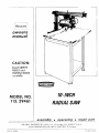
IO-INCH
MODEL NO.
113.29461
RADIAL SAW
assembly
SEARS,
arid
Part No.
63492
ROEBUCK
AP,,D
SIN_IPSONS-SEARS
•
CO..
operating
(_hicago,
LINIITED,
Ill.
60607
Toronto
•
repair
part
U.S.A.
Printed
in U.S.A.
general
safety
rules for power
1. KNOW YOUR POWER TOOL
Read the owner's
manual
carefully.
cation
and limitations
as well as the
hazards peculiar to this tool.
2. GROUND
If tool
11. WEAR
Learn
specific
its applipotential
with
three-prong
plug,
it should
be
plugged
into
a three-hole
grounded
receptacle.
If
adapter is used to accommodate
two-prong
receptacle,
the adapter wire must be attached to a known ground.
Never remove third prong.
3. KEEP GUARDS
and in working
7. KEEP CHILDREN
All visitors
area.
should
in damp
a safe distance
from
sories. The
hazards.
work
Serious
cutting
KID-PROOF
master
switches,
or
by
removing
force
and safer at the rate for which
or attachment
manual
use
improper
of
accessories
position
for
to do a job it was not
for.
the
manufacturer's
with
Standards
2.
That
recommended
cause
if the tool
contacted.
is tipped
or if the
All
lightz
reserved.
compliance
every
motorized
every
tool
That
the
the
tool
_s a sponsor
of
with
That
for
are
tools,
YOU...
including
produced
the
particular
in accordance
Underwriters'
with
Laboratories
tool
applicable
and
American
(ANSI).
4. That
5.
in(:,
Safety
inspection
rules
Institute,
acces-
may
PARTS
power
Seal,
Standards
dependent
tories
(UL),
3
Tool
the
For
Notional
Power
plugging
TOOL
injury could occur
tool is accidentally
associated
I_y
as
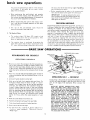
The operation of any power tool can result in foreign objects
being thrown into the eyes, which can result in severe eye
damage.
Always wear safety glasses or eye shields before
commencing
power tool operation.
We recommend
Wide
Vision Safety Mask for use over spectacles, or standard safety
glasses..,
available
at Sears retail or catalog stores.
YOUR
1, That
1969
such
before
accessories
THIS SAFETY SEAL OF THE
POWER
TOOL INSTITUTE
ASSURES
Copyright
safest
and
Before further
use of the tool, a guard or other part
that is damaged should be carefully
checked to assure
that it will operate properly
and perform
its intended
function
-- check
for
alignment
of moving
parts,
binding
of moving
parts, breakage of parts, mounting
and any other conditions
that may affect its operation.
A guard
or other
part that
is damaged
should
be
properly
repaired or replaced.
TOOL
tool
best and
lubricating
ACCESSORIES
owner's
20. CHECK DAMAGED
FORCE TOOL
10. USE RIGHT
WEAR
the
for
STARTING
is in "OFF"
18. USE RECOMMENDED
AWAY
It will do the job better
it was designed.
designed
Keep
for
changing
ACCIDENTAL
Make sure switch
in.
or wet locations.
at all times.
TOOLS
19. NEVER STANDON
-- with
padlocks,
starter keys.
Don't
17. AVOID
accidents.
and balance
before
servicing;
when
blades, bits, cutters, etc.
Consult
be kept
is dusty.
TOOLS WITH CARE
16. DISCONNECT
ENVIRONMENT
8. MAKE WORKSHOP
9. DON'T
footing
Keep
tools
sharp
and clean
performance.
Follow
instructions
changing accessories.
CLEAN
areas and benche.s invite
Don't
use power tools
work area well lit.
operation
Use clamps or a vise to hold work when practical.
It's
safer than using your hand, frees both hands to operate
tool.
KEYS
DANGEROUS
GLASSES
Also use face or dust mask if cutting
Keep proper
Form habit of checking
to see that keys and adjusting
wrenches are removed
from tool before turning
it on.
6. AVOID
to get caught in moving
is recommended
for best
13. SECURE WORK
15. MAINTAIN
order.
5. KEEP WORK AREA
or jewelry
footwear
14. DON'T OVERREACH
IN PLACE
4. REMOVE ADJUSTING
AND WRENCHES
Cluttered
PROPER APPAREL
No loose clothing
parts. Rubber-soled
footing.
12. USE SAFETY
ALL TOOLS
is equipped
tools
has
applicable
and
tool
with
protection
of
Instltute's
adequate
the
standard|
conducted
is inspected
it
manufacturer
of the
safety
testing
under
by
is
assured
Underwriters'
by
in-
Labora-
power.
instructions
and
a llst
of safety
uter.
is a member
of the
Consumer
Safety
Power
Tool
Education
Institute
Program.
and
unpacking and preassembly
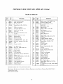
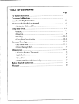
CONTENTS
Page
20
25
27
28
Page
Unpacking and Preassembly Instructions
Alignment
Instructions
................
Electrical Connections
.................
Operating Controls
Basic Saw Operations
.......
3
5
11
..................
.................
13
15
TOOLS
Trouble Shooting
...................
Motor Trouble Shooting Chart
Guarantee
.......................
Repair Parts ......................
............
NEEDED
C_
SCREWDRIVER
(MEDIUM)
SCREWDRIVER
(SMALL)
7116-1NCH
1/2-INCH
9/16-INCH
WRENCH
WRENCH
WRENCH
PLIERS
RUBBER MALLET
PENCIL
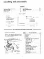
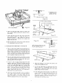
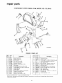
UNPACKING
1. Unpacking
and Checking
AND PREASSEMBLY INSTRUCTIONS
Contents
KeyNo.
(Fi9. 1)
Separate all "loose"
parts from packaging
materials
and
check
each item with
figure
t and "Table
of Loose
Parts" to make sure all items are accounted
for, before
discarding any packing material.
4
NUT
i 44 USED-I
&
DISCARD)
5
1
2
3
4
5
6
7
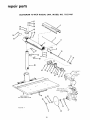
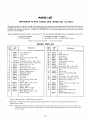
TABLE OF LOOSE PARTS
QW.
Basic Saw assembly ...................
Rear table
.......................
Table spacer
......................
Rip fence
........................
Front table
.......................
"Owner's Manual"
. ..................
Loose Parts Carton
Hex-'L" Wrench,
Hex-'L"wrench,
Hex-"L"wrench,
(containing the following items):
1/8"
. ...............
3/16"
. ..............
1/4"
. ...............
Elevation crank assembly ...............
Knob assembly, pull
.................
Switch key
......................
Arbor wrench .....................
1
1
2
1
Table clamp
.....................
Rip.scale indicator
..................
Twin nut (for attaching rip-scale indicator}
Machine screw, pan-halo,1/4-20x1"'
. .........
Washer, steel (flat), t7/64x518xl!32"
. .......
Lockwasher, medium, 114" . .............
Nut, hex., 1/4-20x7/t6x3/16"
. ...........
Machine screw, pan-hd., 6-32x7/16"'
........
Nut-"T"
. .....................
Setscrew, eup-pt....................
Machine screw, pan-hal., 114-20x1-1/4"
Shaft wrench
.....................
1
1
1
. ......
2
2
.2
G
7
fi
6
4
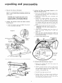
unpacking
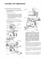
2. Mounting
Your
and preassembly
Saw on a Workbench
Mount on a Craftsman
Power
bench, in such a position
that
free to rotate,
4.
Tool Base or a sturdy, flat
the elevation
crank will be
3.
Installing
Knob
the
(Figure
you
Elevation
are working
on the saw.
Crank
Swivel
and
tighten
Latch-Pin
the
preventing
tracks.
setscrew
d.
Reinstall
any
2
excessive
the carriage
WARNING:
off the arm.
Figure
on
the
carefully
start
and
slide
the carriage
onto
the
radial-arm
tracks. The assembly must be held parallel
with the arm so that all four of the assembly bearings
will smoothly
slide onto
the two arm tracks,
thus
2)
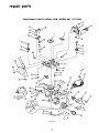
a. Install
the elevation
crank and
on the flat portion
of the shaft.
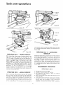
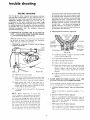
Assembly
a. Rotate
tbe elevation
crank clockwise
several turns
and remove
the shipping
block
from
between
the
carriage and the radial arrn.
b. Remove
the carriage
stop screw.
Iockwasher
and
warning tag.
c. Holding
the carriage
assembly
with
both
hands,
WARNING:
Do not connect the power cord to
a source of power. This cord must remain unplugged whenever
Installing
the Motor
and Carriage
Radial Arm (Figures 2 and 3)
strain
on
the
bearings
and
stop screw and Iockwasher.
Unless this is done carriage
can rol!
e.
Remove
the two shipping
screws from
bottom
of
motor,
and discard.
Leaving
these in would
limit
depth of cut.
f.
Check the cord in the arm cord clip to make sure
there is 30 inches length of cord between this clip and
the cord clip on the yoke.
g.
Install
,_
the swivel
latch
pin knob.
ARM CORE) CLIP
SWIVEL
LATCH-PIf
CARRIAGE
KNOB --
STOP
SCREW
SHIPPING
BLOCK
CARRIAGE
ASSEMBLY
View
above
shows
R-H
indicator
installed.
ELEVATION
C
Figure
5.
Figure
3
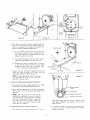
Installing
the Rip Scale Indicators
(Figure
4)
a.
Remove
the carriage
lock
right-hand
carriage cover.
b.
Attach
a rip-scale indicator
to the top of the carriage
cover, using one twin
nut and two 6 32x7/16-inch
pan-head
screws. Tighten
the screws lightly
-- the
indicator
will be adjusted,
later
c,
Reinstall
the carriage
knob,
4
then
remove
the
cover and knob.
Similarly
attach
the remaining
rip-scale indicator
to
left-hand
carriage
cover,
then reinstall
this cover
Note that there is no knob on the left side; only
[he
cever need be removed and reinstalled.
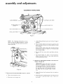
assembly and adjustments
ALIGNMENT
GUARD
INSTRUCTIONS
LOCK
ASSEMBLY
GUABDCLAM_
SCREW
;HT
RECEPTACLE
LATCH-PIN
BEVEL
LOCK
KNOB
HANDLE
KNOB
Figure
NOTE:
The following
instructions
sented in the most logical sequence
they can be done to ensure accurate
ance of your saw.
5
are pre
in which
perform
C.
d.
Loosen the guard-clamp
assembly.
Place the arbor
wrench
screw and
remove
on the shaft
wrench on the hex portion
the saw blade.
of
the guard
nut and the shaft
motor
shaft just inside
Hold the shaft wrench
and rotate the arbor wrench
downward
to loosen the shaft nut. The motor
shaft
has left-hand
threads.
2.
Figure
e.
Remove
collar.
f.
Place the saw blade, nut, collars, and guard assembty
where they
will
be out of your
way during
the
following
adjustment
steps.
the Guard
a, Tight_:n the carriage
b,
Disconnect
lock knob.
the too!-tight
cord.
collar,
saw blade,
Parallel to the
and inner
Radial
Arm
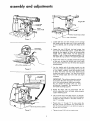
IMPORTANT:
Precise adjustment
of the table
supports
is necessary
to assure consistently
true sawing operations.
If the table supportsand the table - are not precisely squared with
the saw-blade travel in all operating
positions,
the blade
may not produce
clean, uniform
cuts.
6
and Saw Blade
outer
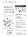
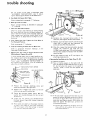
Adjusting the Table Supports
(Figures 7 through 10)
a.
1. Removing
shaft nut,
(Figures
4, 5 and 6)
Loosen the
handle up
bevel
lock
knob
and
b. Swivel the motor counterclockwise
of the shaft is pointing
straight
lock knob.
hold
until
down
the
latch-pin
the saw end
Tighten
the
assembly and adjustments
Figure
10
LATCH-PIN
HANDLE
-FRONT
L-H TABLE
MOUNTING
SCREW
SUPPORT
Figure 7
Loosen both the arm latch handle and the carriage
lock knob so that the radial arm is free to swing right
or left as desired, and the carriage rolls freely on the
arm.
d.
Loosen the two 5/16-inch
hex-head
screws
that
secure the left-hand
table support.
Loosen them just
enough for the support
to move up or down when
tapped with a rubber mallet.
Tap the support
to
position it with its top surface approximately
1/16inch above the top surface of the adjoining
saw base.
Position
the radial arm, and also position
the carriage
on the arm, to place the bottom
end of the motor
shaft directly
above the rear, left-hand, table support
ARM-LATCH
attaching
HANDLE
Figure
screw.
Lay the handle
end of the arbor
wrench
on the
mounting
support
and, while holding the wrench flat
on the support,
carefully
rotate the elevation
crank
to lower
the motor
until the motor
shaft end just
touches the wrench surface.
You should
be able to
8
slide the
resistance.
wrench
back
and
forth
with
only
slight
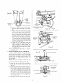
IMPORTANT:
The radial-arm
elevation
setting
must remain the same throughout
the remainder of this table-supports
adjusting
procedure.
Do qot change
the setting
until
you have
satisfactorily
completed
the adjustment
of
both table mounting
supports.
Repeat
the
directly
support
above the front,
attaching
screw.
above
with
the
motor-shaft
left-hand,
end
no_
table-mountim
Tap the front end of the table support,
if necessar3
to move it up or down until the motor shaft end ju,,
touches the arbor wrench in the same manner as i
step "f", preceding.
MOUNTING
Figure
9
Repeat steps "e"
the arbor wrench
and the mounting
the rear and at the
SCREW
j.
Tighten
the two
through
"h" to make certain
tha
fits between
the motor-shaft
en(
channel in an identical manner a
front.
5/16
inch
hex-head
screws.
A CROSS_SECTIONA
VIEW THROUGH
CENTER
OF T-NUT
Figure
L
12
1t4 20x 1" PAN-HD. SCREW
F
U-CLIP
BASE
CROSS-MEMBER
k.
Adjust
the right-hand
same manner,
without
tion setting.
Figure
1/
table support
in exactly
the
altering
the radial-arm
eleva-
FRONT
_
TABLE
[/
knob and, while
up, rotate
the
holding the
motor
to a
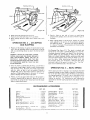
Installing
the Front
Table (Figures
11 through
WASHER
[----;/4t_i2Cx
,1 1/4"'
"_i
I
HEX NUT
PAN
v, ,
lid
I
,__
_
_"
CUP-POI
Figure
73
NT SETSCREW_
and lock
NOTE:
3.
_,
FLAT
°
horizontal
position
then
release the latch-pin
handle so that the pin bottoms
in its detent,
and
tighten the lock knob.
m. Move the radial arm to 0 ° (center) position
it by tightening
the arm-latch
handle.
17/64"
1/4-LOCK
1/4-20
Loosen the bevel lock
bevel latch-pin
handle
F
15)
Setscrew
Figure
14
tightened.
be when
must
not
touch
P_ace the front table (largest) board upside down on
a workbench
or the floor. It is upside down when the
face in which the screw holes are counterbored
is at
bottom.
Note that
there are two
holes near the
is
the
REAR
shown
as it will
For
step
saw base.
TABLE
FRONTTABLE_______
3c
it
BOAR
E
Figure 15
center of the board, one smaller in diameter
than the
other.
Drive the T-nut
(furnished
with
loose parts)
into the smaller of these two center holes.
Turn the front table top side up and place it on the
table supports,
locating
it so that the six screw holes
near the board sides are aligned with
their corresponding holes in the two supports.
C.
In
each
of
the
six
boles
located
above
the
barely
start
the cup-point
TABLE
table
supports,
place one 17/64-inch
flat washer and one
1i4-20xl-inch
pan-head machine screw. In the larger
of the two center holes place one 17!64-inch
flat
washer and one 1/4-20xl
1!4-inch pan-head machine
screw - and start the screw into the U-nut on the
front of the saw base (but
smaller
center
hole {with
1
FRONT
e.
Move the carriage to its extreme
tighten
the carriage lock knob.
f.
Lay the rear table board on edge across the front
table to serve as a straightedge.
Sight under this
straightedge
to determine
whether
the front
table
board is high or low at its center.
g.
If the
center
do not tighten
it). In the
the T-nut
underneath),
rear position,
and
set-screw.
Install one 1!4-inch
Iockwasher
and one 1/4 20 hex
nut on each of the six screws in the table supports,
and tighten
slightly.
The
board
should
be snug
against the supports,
but not held too tightly
to be
moved by tapping it firmly
with a rubber mallet.
front
table is high at center,
(1/4-20x1-1/4-inch)
hold-down
first tighten
screw until
the
the
table is level - then tighten
the leveling screw until
this screw is snug
If table
is low at center,
hrst
tighten
the leveling screw until the table is level then tighten the hold down screw.
assembly and adjustments
4. Squaring the Crosscut Travel (Figures 16 through 23)
Figure 19
a.
Loosen the carriage lock knob, move the carriage to
the approximate
center
of the radial
arm, then
retighten
the lock knob.
b.
Install
(1)
the saw blade,
as follows:
Place on the motor shaft, in this order: 1) One of
the two blade collars, flat face out; 2) The blade,
with
when
The
blade;
(2)
the teeth pointing
in a clockwise
direction
you are facing saw-blade end of motor;
3)
remaining
blade
collar,
flat
face against
and 4) The shaft nut.
Tighten
the shaft
nut as shown
in Figure
17.
c. Loosen the arm-latch
handle 1/4 turn (counterclockwisel, and make sure the yoke clamp handle and the
bevel lock knob are tight.
SAW BLADE_,_,_,_,_,_
OUTER
Figure
__
COLLAB/_
SHAFT
NUT
16
MOTOR
L.
_
INNERCOLLAR
•
-1
Figure
20
CAUTION: WHENEVER YOU MOVE THE RADIAL
ARM BEYOND 45° LEFT OR RIGHT ALWAYS
EITHER PULL THE ARM-LATCH LEVER OUT, OR
COMPLETELY
LOOSEN
THE
ARM-LATCH
HANDLE
BY ROTATING
IT COUNTERCLOCKWISE AS FAR AS POSSIBLE. THE ARM LOCK PIN
MUST BE RETRACTED WHENEVER THE ARM IS
ROTATED PAST 45 ° LEFT OR RIGHT, OR THE
PIN WILL BE DAMAGED, REFER TO "PRECISION
INDEXING"
IN THE "OPERATING
CONTROLS"
SECTION
Figure
17
FOLLOW
RADIAL
ARM
LATCH
LEVER
d,
YOKE
t
Hold
FOR THE
WHEN
CORRECT PROCEDURE
AND INDEXING
ROTATING
TO
THE
ARM.
the arm-latch
lever out and move the radial
arm
approximately
10 ° to the right.
Release the armlatch lever and move the arm slowly to the left until
it indexes at the 0 ° position.
Do not bump or iar
the arm.
Tap the arm latch solidly with the palm of
your hand to seat the arm lock pin firmly.
HANDLE
ARM LATCH
HANDLE
Retighten
the armdatch
handle,
!oosen the carriage
lock knob, and position
the carriage to the rear of
the front
table.
By turning
the elevation
crank
counterclockwise,
lower the blade until it just clears
the front table.
o
BEVEL
LOCK
KNOB
Figure
18
Place a framing
square on the front
table with
its
short leg against the rear edge of the table and the
long leg lust contacting
a tooth of the blade. Mark
this tooth ("A'"
in the illustration)
with a pencil,
MITER
SCALE
ATTACHING
SCREWS
0o
MARK
it'q[
MITER
SCALE
Figure
g.
Figure
21
Figure 23
22
Now slowly
move the carriage
outward
along the
radial arm. The tooth
you have marked
should just
touch
the long leg of the square at all points. If it
does not, make the following
adjustments:
(1)
If your marked
tooth
moves into the square as
the carriage is moved outward,
tap the left-front
edge of the table with a rubber mallet until you
can perform
step "g" correctly.
(2)
If the tooth movesawav
from the square, tap the
right-front
table edge to make the correction
(3)
Recheck until you can perform
step "'g" correctly, then securely tighten
all six of the front table
hold-down
'q" and "j"
screws. Also refer to page 20,
of Trouble Shooting
Section.
steps
MITER SCALE
INDICATOR
TABLE
CLAMP
l
I
FRONTTABLE
REAR
TABLE
SPACER
h.
Loosen
the two
miter-scale
attaching
screws
rotate
the scale to align
its 0 ° mark with
miter-scale
indicator.
Tighten the screws.
and
the
RIP
FENCE
Figure
24
Figure
25
NOTE: This squaring of the crosscut travel will
simultaneously
set both
of the 45 ° index
positions
of the radial arm.
5.
Installing
the Remaining
Table Boards
(Figure
24)
__
a. Position
the rip fence, spacer board and rear
board behind the front table board, as shown.
table
_'_
b.
Install the two table
them at the rear of
securely.
clamps in the slots provided
for
the saw base, and tighten
them
The life of your
saw table will be
lengthened
considerably
if you will cover the
front
table with
a fitted
piece of 1/4-inch
plywood.
This should be tacked in place for
easy replacement.
Use of such a cover will
allow, you to do all cutting
into the cover,
rathe_ than your table top.
Setting
a
The
the Bevel-Index
bevel index
Indicator
indicator
(Figure
should
\ tL
on
0 OS,T,ON
)))Y7"----BEVEL'N°'cAT°R
bevel-index
scale when the
lock
knob
tightened)
into
blade vertical.
b.
0°
BEVEL INDEX
BEVEL
25)
read
_
[
NOTE:
6.
k
the
LOCK
KNOB
motor
is locked
(bevel
position
with
the saw
If necessary,
loosen the indicator
attaching
screw,
adjust the indicator
to theO °reading,then
retighten
the attaching
screw.
assembly and adjustments
Figure 28
7. Adjusting the Rip-Scale Indicators (Figures 26 --29)
NOTE:
The two rip scales and indicators
are
intended only for use in making quick settings.
For maximum
accuracy of setting, make direct
measurements
between
the blade and the rip
fence.
a,
Loosen
the
yoke
clamp
handle,
hold
the
INDICATOR
swivel
latch pin knob up, swivel the yoke until releasing the
swivel latch-pin
knob will allow the yoke to index at
its 90 ° position,
then retighten
the yoke
clamp
handle.
b.
IN-RIP
SCALE
CARRIAGE
Loosen the carriage lock knob and move the carriage
until the saw blade just touches the rip fence. The
blade should be free to rotate while just scraping the
fence. Tighten
the carriage
c. Set the right-hand
LOCK
lock knob.
indicator
at "0".
_ _1
_
NOTE:
With
the
rip fence
positioned
at
normal,
as in figure 27, the bottom
right-side
scale
is used to read the saw-blade
in-rip
setting.
extreme
If the rip
rear position,
Measure
to
the
RIP FENCE
;WIVEL
LATCH-PIN
fence
blade
l
_-_
SPACER BOARD
REAR TABLE BOARD
J
Figure 29
Loosen
carriage
lock knob,
position
rip fence and
blade as shown
in figure
29, tighten
carriage lock
knob, and set left-hand
indicator
at "'12"'.
NOTE:
The top left-side scale is used
the saw-blade out-rip
setting whenever
fence is at the extreme
rear position.
is at the normal
position,
the lower
scale is used.
CARRIAGE
LOCK KNOB
e.
8.
FENCE
Reinstalling
the Guard
Assembly
and Adjusting
(Figure
groove
b. Tighten
_ _-_
swivel
the Anti-Kickback
30)
a. Carefully
fit the guard assembly
the saw blade, seating the inner
Figure 26
to read
the rip
If fence
left-side
After
completing
the indicator
adjustments,
the yoke back to the 90 ° position.
and Spreader
RIP
YOKE
TABLE
KNOB
d.
REAR TABLE BOARD-
the
nearest
fence
is moved
to the
the top scale is used.
CLAMP
YOKE
HANDLE
27
from
tooth.
F--'FRONT
Figure
KNOB
into position
over
guard flange in the
on the end of the motor.
the guard clamp
screw.
c.
Feed the tool-light
cord end between
the yoke and
the motor, and insert the plug into the receptacle
on
top of the motor.
d=
Loosen
bly to
e.
Sight (visually)
to check for proper alignment
of the
anti-kickback
spreader with
the saw blade.
If the
spreader
is misaligned,
adjust it as follows:
Loosen
the two hex-head
screws th3t hold the anti-kickback
the wing nut, lower the anti-kickback
assemlowest position,
then retighten
the wing nut.
I _"
L,
_NT
TABLE
FENCE
I0
electrical connections
mounting
bracket,
shift the spreader into alignment
with the saw blade, then retighten
the two screws to
hold the bracket
securely.
Check to make sure the
spreader is aligned throughout
its travel.
NOTE:
Periodically
check, and maintain
tips on the anti-kickback
pawls.
TOOL-LIGHTCORD RECEPTACLE
GUARD
SCREW
Figure
30
CLAMP
sharp
IMPORTANT:
If you experience
any difficulty in obtaining
trouble-free
sawing operations, refer to the trouble-shooting
section in
this manual.
EYE
9.
Preparing
Rear Table
for Shaping
(Figure
30)
For us_ of a Molding
Head Cutter
(page 17) the rear
table
ruquires
an opening
for clearance
of the motor
end Ct]t this opening as shown in figure 30 inset.
ANTI-KICKBACK
MOUNTING
FOR
SHAPING
BRACKET
POWER
MOTOR
1. Motor
SUPPLY
AND
ANTI-KI
CKBACK
ASSEMBLY
WING NUT
CONNECTIONS
3"---d,
Specifications
The A-C motor
used in this saw is a capacitor-start,
non-reversible
type having the following
specifications:
Horsepower ..............
from saw-blade end
CAUTION:
OPERATION.
................
YOUR
SAW
CONNECT
(2)
(3)
2.50 (developed) @ 120V.
2.50 (developed) @ 240V.
120/240
11/5.5
60
Single
3450
Voltage
........................
Amperes .........................
Hertz (_ ycies) ........................
Phase
..........................
RPM ............................
Rotation as viewed
b.
ELECTRICAL
Clockwise
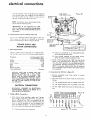
2.
IS WIRED
FOR
120V
TO
A 120V,
15-AMP.
CONN
Either
an
voltage
supplied
by the
the power company
cannot
ECTIONS
Continuous
power
correct.
Remove
terminal
for
120V
A.C.
nameplate
board.
inside
(Figure
heavy-duty
source,
cover
of the
31)
from
motor
motor
must
to
expose
be connected
as
(1)
The
orange-colored
wire
on number
6 terminal.
(2)
The
brown-colored
wire
on number
5 terminal.
Use the
120V
power-cord
plug furnished
with
your
saw.
USE
ON
I?_OV!24-OV
Connections
a. Unde_ normal
home workshop
(full
voltage is supplied to the
operate
efficiently
on 120V,
factory.
However,
if any of the
exists, it wi!l be advisable for
motor for 24OV operation
- to
and I)erformance
for which your
branch
the saw motor.
Motor
wiring
connections
for 120V (as made at the
factory)
are described
below.
Necessary
reconnections for 240V operation
are also described
following. Whenever
changing
connections
from
120V to
FOR
(1)
an overloaded
Low
which
b. The wires
follows:
c.
Motor
or
serving
Connections
a.
WARNING:
CHANGES
IN ELECTRICAL
CONNECTIONS
SHOULD
BE MADE BY A
QUALIFIED ELECTRICIAN.
Changing
undersized
circuit
240V
or vice-versa,
make certain
that a!l necessary
steps (including
proper fusing of the branch circuit)
are completed.
BRANCH
CIRCUIT
AND
USE A 15-AMP.,
TIMEDELAY
FUSE
OR CIRCUIT
BREAKER.
IF THE
MOTOR
IS RECOMMENDED
FOR 240V
OPERATION,
CONNECT
TO A 15-AMP,
BRANCH
CIRCUIT
AND
USE A 1B-AMP.
TIME-DELAY
FUSE OR CIR
CUlT BREAKER.
1,
I
usage, and if proper
motor, your saw will
as connected
at the
following
conditions
you to reconnect
the
obtain the efficiency
saw is designed:
_ROWN
operations.
LEAD
BROW
11
ON
5
7
ORANGE
Figure31
electrical connections
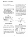
3.
Connections
for
a. The wires
connected
inside the
as fo!lows:
(1)
The
(21 The
b.
Replace
240V
black
blades
wire to
A.C.
(Figure
motor
As soon as the red button
will snap into
running
position,
the saw may be started and operated normally,
by pulling out the saw switch to the "'ON" position.
32)
terminal
box
must
orange-colored
wire
on number
8 terminal.
brown-colored
wire on number
7 terminal.
be
Frequent opening of fuses or circuit
breakers may result
if motor
is overloaded,
or if the motor circuit is fused
different!y
from recommended.
Overloading
can occur if
you feed too rapidly
or if your saw is misaligned
so that
the blade heels. Do not use a fuse of greater capacity
without
consulting
the power company.
the 120V power-cord
plug with a (3-blade)
plug, connecting
the power-cord
white
and
leads, respectively,
to the two "hot"
plug
- and connecting
the power-cord
grounding
the third (neutral)
plug blade.
c. Plug your
d.
240V
saw into a 240V,
3-blade
Although
the motor
is designed
for operation
on the
voltage
and frequency
specified
on motor
nameplate,
normal loads will be handled safely on voltages not more
than 10% above or below the nameplate
voltage. Heavy
loads, however,
require that voltage at motor
equals the voltage specified on nameplate.
receptacle.
Make certain
the receptacle
is connected
to a 240V
A-C power
supply through
a 240V
branch
circuit
having at least a 15-amp. capacity,
and protected
by
a 15 amp. time-delay
fuse or circuit
breaker.
Most motor
connections,
small
size
U3E
I_ROWN
ON
LEAD
ON
troubles may be traced to loose or incorrect
overloading,
reduced input voltage Isuch as
wires
in the
supply
circuit)
or to an
overlylong
supply
circuit.
Always
check
the connections,
the load and the supply
circuit,
whenever
the
motor
fails to perform
satisfactorily.
Check wire sizes
and lengths with the table following.
Figure 32
FOR
I?-0V 240V
,5
terminals
U
7
_
---4"
\-_
,. I I_.j-T---
.L...._r
ORANGE
12345
ON
LEAD
6
_t_
NAMEPLATE
BROW
MOTOR
ORANGE
OVERLOAD
Your saw motor is equipped
overload
protector
designed
when the motor
temperature
33).
The following
table
lists recommended
wire
sizes for
connecting
the motor
to the power source.
These sizes
should be maintained
for trouble-free
operation
of the saw.
If an extension
cord is used, it should be a 120V or 240V,
with a manual-reset,
thermalto open the power-line
circuit
exceeds a safe value (figure
3-wire
will not snap into place immediately,
too hot and must be allowed to cool
(An
audible
click
will
indicate
50
100
100
150
200
the motor
for a while
protector
type designed
Length of the
Conductor
2. After
cooling
to a safe operating
temperature,
the
overload
protector
can be closed manually
by pushing in
the red button
on the top of the motor.
If the red
longer.
closed.)
33
WIRE SIZES
If the protector
opens the line and stops the saw motor,
immediately
press the saw switch
to the "OFF"
position, and allow the motor to cool.
button
is still
MOTOR
Figure
SAFETY PROTECTION
NOTE:
This motor
should
be blown
out, or
"vacuumed",
frequently
to prevent
sawdust
interference
with normal motor ventilation.
1.
PROT_
feet
feet
feet
feet
feet
or less
or less
to 150 feet
to 200 feet
to 400 feet
NOTE:
size must
to deliver
is
12
for
]rounding
the tool.
Wire Size Required
(American Wire Gauge Number)
240 Volt Lines
_114
No. 12
No. 10
No.
No.
8
6
120 Volt Lines
NO. 12No. 10
No. 8
,
i
I
No
No.
For circuits
of greater length, the wire
be increased proportionately
in order
ample voltage to the saw motor.
6
4
U_,_t;_l
Lt i ili_
LUlilIUI_
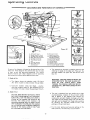
LOCATIONS
AND
FUNCTIONS
OF CONTROLS
7
8
yo_J!
_T
Figure 34
10.
Elevation
11,
Bevel
Rip Scale and
Indicator
Miter
Scale and
Indicator
12.
Anti-Kickback
13.
14.
Guard
Bevel
15.
On-Off
16.
Sawdust
1"7.
Sawdust-Chute
18.
Arm-Latch
1.
2,
Arm-Latch
Lever
Swivel
Latch-Pin
3.
4.
5.
Carriage
6.
Yoke
7.
8.
Key
Latch-Pin
9,
Bevel-lnde×
and
Lock
Knob
Spreader
Knob
Clamp
Handle
Handle
Scale
Indicator
A series of six diagrams
is located on the top surface of the
radial arm. These designate the controls
that must be used
a.
in basic set-ups
and operating
procedures.
You
should
become
familiar
with
these diagrams
and the operating
instructions
that follow,
before operating
your saw.
1.
Depth
a. The
34),
Knob
and
Assembly
Clamp
Index
Screw
Handle
Switch
Chute
Lock
Handle
Knob
€
(Knob)
Two controls
are involved
in releasing, securing and
indexing
the angle of the radial arm. These are: the
arm-latch
handle
(18, figure 34), and the arm-latch
lever (1).
of Cut
WARNING:
THE SAW SHOULD NEVER BE
OPERATED WITH THE SAW BLADE OUTSIDE
OF THE
TABLE
AREA,
EVEN
THOUGH THE RADIAL ARM CAN BE ROTATED A FULL 360 ° AND LOCKED IN ANY
POSITION.
diagram
shows the elevation
crank (10, figure
which is used to raise and lower the saw blade.
b. Clockwise
rotation
raises
the
blade..,
clockwise
rotation
lowers
it. One complete
the handle will raise or lower the saw blade
2.
Crank
Lock
counterturn of
1/8-inch.
Angle of Cut
b.
CAUTION:
ANY
WHEN
DIRECTION
ALWAYS
FIGURE
TATING
THIS
DEXING
THE
BEYOND
RADIAL
45 ° (LEFT
ARM
IN
OR RIGHT_,
THE
ARM-LATCH
HANDLE
WOULD
PREVENT
OF
RADIAL
ARM
45 ° POSITIONS
THE
(18}
UNTIL
IT STOPS, TO PRETHE ARM-LOCK
PIN, DAMAGE
NATURE
(LEFT
OR
AT
PROPER
THE
The arm is unlocked
from
counterclockwise
rotation
any position
by a slight
of the armlatch
handle
and is locked
in any
desired
miter
position
by
rotating
the arm-latch
handle clockwise
until tight.
O
O
The radial arm has positive stops at 0 and 45
left
and right, and is released from these index positions
by unlocking
the arm-latch
handle
1/4 turn,
and
pulling out the arm-latch
lever.
PULL OUT THE ARM-LATCH
LEVER
(1,
34). OR LOOSEN
THE
LEVER
BY RO-
COUNTERCLOCKWISE
VENT
DAMAGING
OF
MOVING
IN-
0 ° AND
For the most
index positions,
RIGHT}.
13
positive
and
the following
accurate
settings
is recommended:
at
the
operating
(1)
(2)
controls
If the radial arm is already
indexed,
rotate the
arm-latch
handle ( 18, figure 34) 1!4turn
counterclockwise
from the locked position,
pull out the
arm-latch
lever, and move the radial arm off the
index position_ Release the arm-latch
lever.
Move
the
radial
arm
into
the
desired
6.
3.
Yoke
Lock the radial
handle clockwise
arm
until
by rotating
tight.
the
and Key
a. This saw cannot
be operated
without
the key,
the key cannot be removed
from the lock while
saw motor is running.
index
and
the
To release the switch lever (15, figure 34) insert the
key (7, figure 34) in the slot and turn
it counterclockwise
until
it stops. Rotate the key clockwise
to lock the switch.
b,
position
(do not bump or jar it) and push on the
arm-latch
lever solidly
with
the palm of your
hand (figure 34 inset). This is very important
as
it ensures proper seating of the arm lock pin in
the arm latch, thus always setting the arm at the
correct
position.
(3)
Power Switch
c. To start the saw, engage
left
side of the switch
outward.
your forefinger
lever and pull
under the
the lever
d
push
lever with
arm-latch
lo stop the saw, simply
finger or thumb.
the switch
Pivot
WARNING:
a. Two controls
are used in this operation.
They ate:
the swivel latch-pin
knob (2, figure 34) and the yoke
clamp handle (6, figure 34).
b.
lock
POSITIONING
SAWDUST CHUTE, AND
ANTI-KICKBACK
AND SPREADER
ASSEMBLY, FOR RIPPING
A swivel latch pin automatically
indexes the yoke at
each
90 ° position.
Lift
the spring-loaded
swivel
latch-pin
knob to release this pin.
WARNING: NEVER POSITION THE GUARD
CHUTE
OR ANTI-KICKBACK
ASSEMBLY
WITH THE POWER ON. NEVER POSITION
THE ANTI-KICKBACK
PAWLS BY GRASPING THE PAWLS OR SPREADER.
e. The yoke clamp handle locks the yoke to the carriage
in any position.
Pull the handle forward
to release
the yoke;
push the handle
rearward
to secure the
yoke.
4.
Carriage
a.
Lock
The carriage
lock
knob
(5, figure
clockwise
to secure the carriage
on
and counterclockwise
to release it.
For all crosscutting
operations
(those operations
in which
the carriage is traveled
along the radial arm to feed the saw
blade into
the workpiece)
both the sawdust chute
(16,
figure 34) and the anti-kickback
and spreader assembly (12,
figure 34) must be elevated
to clear theworkpiece
or the
fence, whichever
is higher.
34) is rotated
the radial arm,
b. When performing
a square or miter-angle
crosscut,
the carriage lock knob must be rotated counterclockwise until the carriage is free to travel along the arm.
This knob
should
be tightened
except
when the
operator
is ready to grasp the bevel index handle (14,
figure 34) and rnake a cut.
5.
1. The Anti-Kickback
being ripped.
assembly.
controls
used in angular
positioning
and
of the
motor,
to provide
the desired
(bevel) angle, are: the bevel lock knob (t 1,
and the latch pin handle (8, figure 34).
b. The bevel-index
angular
position
horizontal,
from
b.
scale (9, figure 34) indicates
the
of
the
motor
with
respect
to
0 ° to 90 ° in either vertical position.
c. The bevel latch pin automatically
indexes the motor
at 0°, 45 ° and 90 ° up and down.
Lift
the spring
loaded
latch-pin
handle to release this pin. At any
other
d.
position,
the latch
Assembly
Figure
A
wing
nut
in the guard
secures
pawls
by placing
the workpiece
35
yoke
knob
_I
WORK
14
the
The anti-kickback
and spreader
assembly
is positioned
by grasping
the top of the light
housing
assembly (23, figure 3 on p. 30), I9osening the wing
nut, and raising or lowering
the assembly
until the
anti-kickback
pawl point nearest the saw blade rests
on the top surface of the workpiece,
with the bottom
edge of the pawls angled slightly
downhill
to the top
surface
of the workpiece.
(See figure 35.)
Before
making
the cut,
check
the effectiveness
of the
anti-kickback
pin does not engage.
The bevel lock knob locks the motor
to the
when the motor is in any position.
Rotate the
cloekwise
to lock, counterclockwise
to unlock.
and Spreader
The anti-kickback
and spreader assembly
(12, figure
34) is used during
ripping
operations
and is adjustable to accommodate
the thickness
of the board
Blade Angle
a. The two
indexing
saw blade
figL_re 34)
When leaving the saw unattended,
the ON-OFF
switch and remove the key.
KICKBACK
under
basic saw operations
the pawls and attempting
to slide it in the direction
of kickback.
If the pawls do not catch,
further
adjustment
is necessary.
e
When
positioning
the anti-kickback
and spreader
assembly for bevel ripping,
lower the assembly until
the Iocknut just clears the workpiece.
If the pawls do
not catch, further
adjustment
is necessary.
d.
Before repositioning
the yoke to the
tion, false the anti-kickback
assembly
limit and secure.
e.
2.
The
tips
of
the
checked occasionally
The Sawdust
the top surface of the board
the knob secures the chute.
c.
crosscut
posito the upper
anti-kickback
pawls
and kept sharp.
should
PRECISION INDEXING
Experienced
operators of precision
equipment,
such as your
Craftsman
Radial-Arm
Saw, normally
acquire the habit of
indexing
the machine
in one direction
only, whenever
a
new setting is made in preparation
for a different
operation.
For
example:
when
moving
the radial
arm to a new
position,
it is advisable to move it slightly
past the desired
index position,
then return
it slowly and carefully
to latch
be
Chute
and lock it. Figure 34 inset shows the radial arm being securely indexed
by "tapping"
the arm latch lever with the
palm of the hand. Swivel indexing
and bevel indexing
can
be accomplished
in a similar
manner
This indexing
technique tends to neutralize
any stresses imposed upon the saw
components,
and contributes
to the high degree of accuracy
the saw is capable of producing
when operated expertly.
The sawdust
chute
is positioned
by grasping
the
upper tab et lower end of chute, loosening the knob
(17, figure 34) and raising or lowering
it to just clear
BASIC SAW
the yoke to the crosscut
posito the upper limit and secure.
IMPORTANT:
In ripping
operations
the workpiece is always fed from the sawdust chute side,
never from the anti-kickback
side of the guard.
(See figures 41 and 42.)
a. The sawdust
chute
(16, figure 34) is used to help
prope!
sawdust
from
the cut and provide
a holddown for boards during ripping.
b
Before repositionlng
tion, raise the chute
being ripl_ed_'T-_ght_'_n_
OPERATIONS
CARRIAGE
REQUIREMENTS
(OPERATIONS
FOR
LOCK
CROSSCUT
1 THROUGH
4)
YOKE CLAMP
HANDLE
BEVEL
LOCK KNOB
1. Be sure you return the carriage to the full rearward position at the conclusion
of each cut. Never remove your
hand from the bevel index handle unless the carriage is
in this position.
Allow the saw blade to come to a complete stop before removing
the workpiece
from the saw
table.
2. Arbor nut
a horizontal
position.
must be tight and saw blade guard installed
position
with anti-kickback
device in full
3. Arm
handle
latch
Figure 36
in
up
OPERATION
(knob)
must
Work must be held firmly
against table and fence. For
workpieces
thicker
than the fence is high, it is recommended
that a higher fence be cut (at least workpiece
thickness)
and inserted
for that operation
being performed.
Always
place the fence in the most forward
position
(farthest
from the column support)
compatible
with the workpiece
being processed
and the operation
being performed.
With the carriage
fully
retracted,
the
blade should
not
against the fence,
contact
within
6.
should
be sharp and correctly
7. Yoke
clamp
8. Bevel index
handle
knob
must be in locked
of
it and using
the fence
as a supworkpiece.
Never
crosscut
free-
sawing
the
workpiece
saw blade.
USING
WHEN
THE SAW, IT WILL
PULLING
THE SAW
BE NOTICED,
THAT
TOWARD
YOU DUR-
ING
CROSSCUTTING,
THE
BLADE
TENDS
TO
FEED
ITSELF
THROUGH
THE
WORK
DUE TO
THE
ROTATION
OF
THE
BLADE
AND
THE
DIRECTION
OF THE
FEED.
THEREFORE,
THE
OPERATOR
SHOULD
DEVELOP
THE HABIT
OF
HOLDING
HIS RIGHT
ARM
STRAIGHT
FROM
THE SHOULDER
TO THE WRIST.
position.
must be tight.
9. For operations
No. 3 and No.
struetions
under
paragraph,
"Blade A_gle".
process
through
of the
set.
the workpiece
when placed
the stated capacities
of your
Hands must be kept well away from
is the
ing the saw blade
port
for
the
edge
hand.
WARNING:
BEFORE
CROSSCUTTING,
MAKE
SURE
THE
ARM
LATCH,
BEVEL
LOCK
AND
YOKE
CLAMP
ARE ALL SECURED,
NEVER
USE
A LENGTH
STOP OR A FIXED
GUIDE
ON THE
FREE
END
OR EDGE OF A WORKPIECE.
(SEE
INSTRUCTION
15 UNDER
"'SAFETY
INBTRUCTIONS
TO OPERATOR".)
DO
NOT
CROSSCUT
WORKPIECES
THAT
PLACE
YOUR
HANDS
CLOSE
TO THE
PATH
OF THE
SAW
BLADE.
WHEN
MORE
EXPERIENCE
IS GAINED
BY
saw.
5. Blade
NO. 1 -- CROSSCUT
be tight.
Crosscutting
4.
KNOB
4, observe additional
in
"Operating
Controls",
15
by
pull-
basic saw operations
RADIAL
ARM
RADIAL
ARM
CARRIAGE
Figure
37
RADIAL
ARM
ARM
CARRIAGE
YOKE
Figure
full rearward
to a complete
the saw table.
Figure
OPERATION
NO.
2 -- MITER
crosscutting
is the
process
of sawing
a board
at any
crosscutting
OPERATIONS
of sawing
of miter
and bevel
5 AND
6
1. Carriage lock knob must be tight.
2. Radial arm must'be locked in 0 ° position.
3. Saw blade
must
be parallel
to fence,
to minimize
possibility
of kickbacks.
4. Work must be held firmly
against table and fence while
feeding through.
5. Guard chute and anti-kickback
pawls must be properly
set. Observe
instructions
under "ADJUSTING
GUARD
CHUTE
AND
ANti-KICKBACK
AND
SPREADER
ASSEMBLY
FOR RIPPING
OPERATIONS",
preceding.
NO. 3 -- BEVEL CROSSCUT
is the process
is a combination
REQUIREMENTS FOR RIPPING
should be returned
to full rear position,
and the saw blade
allowed
to come to a complete
stop, before removing
the
workpiece
from the saw table,
Bevel
crosscutting
crosscutting.
(See figure 39) The radial arm and bevel are
set to produce
the desired cut; the yoke is indexed
at 0 °
and locked. The board is held firmly
against the fence, and
the carriage
is pulled
forward
along the radial
arm to
produce
the cut. Again, the carriage should be returned
to
full rearward
position,
and the saw blade allowed to come
to a complete
stop, before
removing
the workpiece
from
the saw table.
angle other than a 90 ° (square) cut. (See figure 37.) The
45" miter angle is a popular
one, since two boards cut at
45 ° can be assembled to form a 90 ° corner for producing
a
square or rectangular
frame. The radial arm is set to the
desired angle of cut, and the yoke and bevel settings
are
o
indexed at 0 (and locked), as in square crosscutting.
The
board being cut is held firmly
against the fence, and the
carriage
is pulled
forward
along the radial arrn to perform
the desired
cut.
As in "Operation
No. 1", the carriage
OPERATION
NO. 4 -- COMPOUND
CROSSCUT
CROSSCUT
Compound
Miter
position,
and the saw blade allowed to come
stop, before removing
the workpiece
from
OPERATION
38
40
at 90 ° (square)
across the board with the saw blade set at an angle other
than 90 ° 1o the saw table
(Bee figure 38.) The radial arm
and yoke are indexed at 0 ° and locked, but the bevel _sset
'co the de<,ired angle of cut. The board is held firmly against
the fence, and the carriage is pulled forward
along the radial
arm to p_oduce the cut. The carriage should be _eturned to
16
YOKE
Figure
4. Stand
a little
to one side of center
to avoid being
sprayed with sawdust and to be clear of work in case of
kickback.
6. Blade should be sharp and correctly
set.
7. Hands must be kept wellaway
from saw blade.
8. When ripping
narrow or short stock, always use a push
board.
5. When ripping
short or narrow
work, always use a push
stick applied
to the section of the workpiece
between
the blade and fence . .. push the work past the blade so
it is clear of the blade. This procedure
will minimize
the
possibility
of kickbacks.
OPERATION
NO. 5 -- OUT-RIPPING
AND IN-RIPPING
1. Ripping
is the process of sawing the workpiece
by feed
ing it into the saw blade when using the fence as a guide
and as a positioning
device to obtain the desired width
of cut.
WARNING:
2.
NEVER
RIP FREE-HAND.
Out-Ripping
(See
locked at 0 °. The
clockwise
direction
BEFORE
figure
41.1 The bevel is indexed
and
yoke is turned
90-degrees in a counter(viewed from above), from the crosscut
RIPPING, MAKE SURE THE GUARD, SPREADER
AND
ANTI-KICKBACK
PAWLS ARE SET UP
position.
When you are standing
in front
of the saw, the
blade will rotate
clockwise.
Before positioning
the guard
chute and anti kickback
pawls, lower the blade to just cut
PROPE R LY. ALSO, MAKE SURE THE SAW
BLADE IS PARALLEl
WITH THE FENCE. NEVER
RIP WORKPIECES SHORTER
THAN THE SAW
BLADE DIAMETER.
into
the table.
After
positioning
the guard
chute
and
anti-kickback
pawls, the workpiece
is fed from
the chute
(left-hand)
side of the guard, as shown.
The "Out Rip"
scale is on the left-hand
side of the radial arm,
Since the work is pushed along the fence, it must have a
reasonably
straight edge in order to make sliding contact
with the fence. Also, the work must make solid contact
with
the table, so that it will not wobble.
Provide
a
straight edge, even if this means temporary
auxiliary
straight-edged
board to the work.
piece is warped, turn the hollow side down,
3.
42
OPERATION
Always use the saw guard and make sure the spreader is
correctly
aligned with the saw kerr. Wood cut with the
grain tends to spring the kerr closed and bind the blade
and a kickback could occur.
applicable
ripping.
RECOMMENDED
CAT.
9 10315
9 1038
9-1071
9 2954
9 3230
Key Chuck
Miter Vise
9 2980
9 3279
Molding
Molding
Rotary
......................
.......................
Head Guard
Head Guard
Surface
- 7-Inch
- 8-Inch
Planer
Sanding Plate - 10-Inch
The above recommended
......
........
- Carbide
lip
............
accessories
BEVEL RIPPING
ripping
operations
also apply
ACCESSORIES
ITEM
Sanding Wheel
Sanding Wheel
Dust Collector
9-29524
9-29523
.
to normal
NO.
Cabinet
.........................
Stand ...........................
Bench
..........................
Shaper Fence .....................
Hold-Down
Attachment
............
6 --
Bevel ripping is either in-ripping
or out-ripping
as de_ribed
preceding,
except the saw blade is tilted out of perpendicular to the saw table surface. Figure 42 shows a typical bevel
out-ripping
operation.
The bevel is set to the desired bevel
angle, and the yoke is positioned
for in-ripping
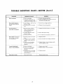
or out
ripping,
as required.
All
requirements
and observations
nailing of an
If the work-
ITEM
NO.
9 29513
CAT.
- 8Inch
.............
- 10-Inch
...........
....................
9 2274
9 22723
9 16996
Taper Jig .......................
Satin Cut Dado - 7-Inch ............
Satin Cut Dado8-Inch
...........
Heavy Duty Dado8Inch
..........
Molding
Head Single Cutter.
.........
Molding
Head Three Cutter ..........
Sanding Drum - 3-Inch ...........
9 3233
9-3257
9-3253
932473
9 3215
9 3221
9 25246
Lower
9 29008
Ring Guard
.................
9 22724
are current
and
17
NO.
were
available
at the
time
this
manual
was
printed
to bevel
safety
instructions
1. Be sure to read the following
before operating
the saw.
instructions
WARNING:
DO NOT CONNECT
CORD
UNTIL
THE FOLLOWING
HAVE
BEEN
SATISFACTORILY
PLETED.
a. Assembly
b.
c.
to operator
carefully
Ripping
by applying
the workpiece
that
piece (feed force when ripping
should
always be
applied between the saw blade and the fence..,
use
a push stick for narrow or short work),
POWER
STEPS
COM-
g.
Review and understanding
dures which follow.
of
the
with
control,
operating
3. Set carriage
lock
be bolted
before
proce-
Always
6.
machine.
5.
Kickbacks
can cause serious injury. A kickback
occurs
when a part of the workpiece
binds on the saw blade
and the rip fence or other fixed object, rises from the
table,
and is thrown
toward
the operator.
Kickbacks
are usually
caused by one or more of the following
conditions:
to slope
forward
wearing
safety
goggles...
Whenever
possible, perform
rip, bevel rip, and plough
cuts with the saw in the out-rip position.
This provides
the most stable setup (carriage
bearings
nearest
the
column)
and the greatest visibility
of the sawblade.
so neither
to stand in
B,
Before starting
work, verify that no play exists in the
carriage and that arm, yoke, and bevel locks/clamps
are
tight.
9,
Use only
accessories
10.
The saw
non-glare
work
light
badly
set,
that are designed
area should
and adequate
11. A large proportion
improperly
for this
machine.
have adequate
overhead,
surrounding
work space.
of saw accidents
filed cutting
is caused by dull,
tools, by gum or
the
saw
resin adhering
to cutting tools, and by fence misalignment (out-of-parallel)
with the sawblade.
Such conditions cause the material
to stick, jam, stall the saw, or
kick-back
at the operator.
Cracked saw blades should
be discarded
immediately.
A sawblade
can become
cracked
if it wobbles or if it is not in balance.
Never
and the saw
attempt
to free a statled saw blade without
turning
the
saw "OFF".
Avoid potential
injury
by proper cutting
tool and machine maintenance."
a. Failure to use a spreader when ripping, or failure to
maintain
the spreader
in alignment
with
the saw
blade.
Improperly
conditioned
(dull) saw that permits
material
to pinch on the out-feed
edge of the
and rise from the table.
c,
Failure to determine
that the rip fence
blade are parallel to each other.
d.
Ripping
wood that has a twisted
grain, does not
have a straight
edge to guide along the fence, or
wood that is twisted or not fiat (which may rock on
the table and pinch the blade).
e.
Confining
piece when
pre-
above...
The saw should be positioned
when ripping
the operator
nor a casual observer is forced
line with the saw blade.
Position
your entire saw (or saw and bench)
slightly
rearward,
so the carriage will not roll
due to gravity.
the cut-off
be
Keeping your face and body always out of line
of possible
kickbacks,
including
turning
the
switch ON and OFF ...
4.
b.
any of the causes noted
may
Making
sure (by trial)
before starting
the cut
that the anti-kickback
pawls will stop the kickback once it has started...
down.
moving
operation
is complete...
all the way past the saw
Injury
from
kickbacks
or minimized
by:
Avoiding
ONrip
CAUTION:
Always disconnect
the power when
changing the sat-up,
or making adjustments.
Shut off motor before performing
layout work
on the saw table. ALWAYS
return the carriage
to the full rear position after each crosscut Wpe
operation.
2. The saw should
Releasing workpiece
before
not pushing the workpiece
blade.
NOTE:
vented
and installation.
Examination
and operating
familiarity
OFF switch, elevation
control,
bevel
control,
and miter control.
the feed force to the section of
will become the cut-off
(free)
CAUTION:
DO NOT cycle the motor switch
ON and OFF rapidly, as this might cause the
saw blade to loosen. In the event this should
ever occur, allow
the saw blade to come to a
complete stop and re-tighten
mally, not excessively.
ripping.
18
the arbor
nut nor-
12.
Gloves should
not be worn while operating
the saw.
Loose flowing
garments,
jewelry
(rings, wrist watches,
etc.} and neckties should never be worn. Long sleeves
should be rolled to above the elbows.
13.
Always wear safety goggles to protect the eyes. In addition. wear a face shield if the operation
is dusty, and
ear protectors
(plugs or muffs) during extended
periods
of operation.
14.
15.
21.
the diameter
for which
the saw was designed.
For
greatest
safety and efficiency
when ripping,
use the
maximum
diameter
blade for which
the saw is designed,
nearest
17.
Make sure your fingers do not contact
power or motor plugs when installing
plug to or from a live power source.
18.
Never climb
on or near the saw when power
is on.
Never leave the saw with power on, or before the cutting tool has come to a complete
stop. Lock the motor
switch and put away the key when leaving the saw.
19. Avoid
could
cutting
cutting
piece.
awkward
hand positions,
cause a hand to move into
the terminals
of
or removing
the
the
spreader
is
Do not position
the arm so the operation
you are performing
permits
the cutting
tool to extend beyond the
edges of th_e table.
24.
Never turn your radial arm saw "ON"
before clearing
the table or work surface of all objects (tools, scraps of
wood, etc.) except the workpiece
and related feed or
support devices for the operation
planned_
25.
Objects can be thrown
upward toward the operator
by
the back of the blade if proper
operating
procedures
are not followed.
This usually
occurs when a small,
loose piece of wood or other object contacts
the rear
of the revolving
blade. It can be avoided by removing
all loose pieces from the table immediately
after they
are made, using a long stick, and keeping the guard in
place at all times. Use extra caution
when the guard
assembly is removed for molding,
and replace the guard
as soon as that operation
has been completed.
means
perform
feeding
any operation
"free hand".
This term
the carriage into the workpiece
or feed-
ing the workpiece
into the saw blade or other cutting
tool
without
using the fence or some other
device
which prevents
rotation
or twisting
of the workpiece
during the operation.
Never "rip"
(cut with the grain)
narrow
or long workpieces
in the crosscut position...
feeding saw blade into the stationary
workpiece.
Never
make a miter
cut with
the arm in the 90 ° crosscut
where a sudden slip
a saw blade or other
position.
27. Safety
Always
conditions
23,
26. Never
tool.
Never reach in back of or around
the
toot with either hand to hold down the work-
CAUTION:
Never
reposition
CHUTE
or anti-kickback/spreader
ON.
20.
these
abrasive or cut-off wheels, or wire wheels
can be dangerous
and is not recommended.
(Abrasive
or cut-off
wheels are used to saw many different
materials including
metals, stone, and glass.)
Never use a length stop on the free end or edge of the
workpiece.
Never hang onto or touch the free end of
workp*ece,
or a free piece that is cut off, while power
is "ON"
and!or the saw blade is rotating.
In short, to
guard against kickbacks
or other potential
accidents,
the cut-off
piece in any thro-sawing
operation
must
never be confined
-- it must be allowed to move laterally.
Do not leave a long board unsupported
so the spring of
the board causes it to shift on the table. A support
should be used to catch the end of the board you are
supporting.
since under
the blade.
22. The use of
Provide proper support
for the workpiece,
based on its
size and the type of operation
to be performed.
Hold
the work firmly
against the fence. When ripping
short
workpieces
(under
12-inches
long) or narrow
pieces
(under
6-inches wide), use a push stick applied to the
section
of the workpiece
between
the blade and the
fence.
16.
Do not use any blade or other cutting
tool marked for
an operating speed in excess of the design speed of the
saw. Never use a cutting
tool larger in diameter
than
position
the
GUARD
the
GUARD
with power
CHUTE
and
the
alertness
is a combination
of operator
common
sense and
at all times when the saw is being used.
WARNING: DO NOT ALLOW FAMILIARITY
(GAINED FROM FREQUENT USE OF YOUR
SAW} TO BECOME COMMONPLACE"
AU
WAYS REMEMBER
THAT A CARELESS
FRACTION OF A SECOND IS SUFFICIENT
TO INFLICT SEVERE INJURY.
anti-
kickback
and spreader assembly
for rip type
operations. Also make sure the cutting
tool, arbor collars
and arbor nuts are installed
properly.
Keep guards in
place; use the proper guard.
19
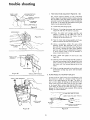
trouble shooting
TROUBLE
SHOOTING
out of the column
in the outer end of
be loosened
while
and tightened
with
Even though
the finest materials
and precision
workmanship have been incorporated
into your Craftsman
saw, it is
reasonable
to expect some wear after long periods Gf use.
Adjustment
facilities
have been built
into the saw to
adjustment
has been completed.
This screw
applies pressure on the nylon friction
plug, and
provides
smoother
elevation
movement
of the
compensate
for this wear. Looseness due to wear, rough
handling,
or improper
adjustments
will usually be indicated
by reduced accuracy
or the inability of the saw to perform
as intended. The usual operating
troubles
are listed in the
following
paragraphs,
with
the
necessary
corrections
described
and illustrated.
column
tube ...
and should be tightened
to
provide
maximum
smoothness
of operation.
References
to right- and left-hand
positions are
as indicated
in the illustration.
b.
1. LOOSENESS OF COLUMN TUBE IN COLUMN SUPPORT - ELEVATION
CRANK OPERATES ROUGHLY, OR CHATTERS WHEN ROTATED
of Column
Tube
Adjusting
Column
Tube
Key (Figure
COLUMN
44)
TUBE
FRICTION
PLUG
INylon)
When this condition
exists, square crosscuts are likely to
be difficult
to make,
and repeated
cuts inaccurate.
Adjust the column tube key as follows:
a. Checking
for Looseness
Support
(Figure 43).
tube keyway.
The setscrew
the column tube key must
adjustment
is being made,
medium
firmness
after the
COLUMN
SUPPORT
in Column
RACK-UP
PLUG (Steel)
(Righ t-Hd.}
ARM
CREW
(Left-Hd.)
Figure
(1)
Loosen
column
the setscrew located
tube key (figure 44).
(2)
Loosen
the left-hand
(3)
Tighten
the right-hand
(4)
Tighten
the left-hand
(5)
Rotate the elevation crank to raise and lower the
radial arm. If too tight,
loosen the right-hand
setscrew
slightly,
and check again for smooth
operation.
When correct,
tighten
the left-hand
setscrew.
(6)
Tighten
the setscrew located in the center of the
column
tube key until smoothest
operation
is
obtained.
Figure 43
(1)
Tighten
(2)
Grasp
the arm-latch
the
arm-latch
handle
handle
with
one
hand
and
hold a finger of the other hand at the parting line
between
the column
tube and column
support.
(3)
(4)
2.
Apply
gentle
side force to the radial art]] in
opposing
directions.
Any
!ooseness
bet_Jeen
column and column
support (indicated
by arrow
in figure 43) can be felt with finger.
If looseness
Jperations:
can be felt,
perform
the
44
BLADE
DOES
NOT
ACCURATE
REPEAT
in the
setscrew
center
of the
1/4 turn.
setscrew.
setscrew.
MAKE
SQUARE
CUTS,
CUTS CANNOT
BE MADE
AND
If this condition
exists the trouble
might be due to any
one, or a combination
of, the following
conditions:
a.
following
Looseness
port.
Adjust
and b.
Between
as described
Column
Tube
in preceding
and Column
paragraph
Sup-
"1",
a
NOTE:
Before
attempting
to
adjust
the
column
tube key, the function
of this adjustment should be understood.
Figure 44 shows a
sectional
view through
the column
tube support (looking
downward}
at the column
tube
b.
Crosscut
Travel
Not
Properly
Adjusted.
Refer to "ALIGNMENT
INSTRUCTIONS",
step "4.
Squaring
the Crosscut Travel",
preceding.
If crosscut
travel
cannot
be adjusted
as described,
refer
to
paragraph
"i", following.
key location
By loosening
the left-hand
setscrew and tightening
the right-hand
setscrew
the column tube key will be forced tighter into
the column
tube keyway.
Conversely,
loosening the right-hand
setscrew and tightening
the
left-hand
setscrew wilt retract the column
key
c. Table
Correct
with
table
20
Supports
Not
adjustment
Properly
Adjusted.
of table
supports
can be checked
satisfactory
accuracy,
without
removing
boards, by checking
at the various positions
the
on
trouble shooting
the top surface
of the table,
as described
under
"ALIGNMENT
INSTRUCTIONS",
step "2. Adjusting the Table Supports Parallel to the Radial Arm".
d. Saw Blade
Adjust
Not
Square
as described
e. Bearings
Yoke
Table.
"j",
following.
Loose on Tracks.
Adjust
carriage
"k", following.
f.
With
in paragraph
bearings
Does Not
Index
as described
in
RIP
FENCE
paragraph
Properly.
Check for proper
yoke
the swivel latch pin fits
swivei latch-pin
housing
hand carriage cover) are
as described
in "3. Blade
ARM-LATCH
HANDLE
indexing
by noting whether
into its detents properly.
If
screws (located
under leftloose, readjust blade for heel
Heels to the Right or Left",
SQUARE
following.
g. Yoke Clamp Does Not
Full Rearward Position.
h.
Tighten
Refe( to paragraph
"1", following.
Improper
Indexing
of Radial
Refer
to
Operating
paragraph
"Precision
Controls
section.
i. Adjusting
the
Maladjustment
the
Arm
Yoke
Cuts.
Indexing",
in
Arm Latch to Correct
(Figures 45 and 46).
Crosscut
I
t_ -,m-------
ATTACH.
INDICATOR
Recheck travel of blade tooth A with the square
(figure
46), to make sure that tightening
the
screws did not affect the adjustment.
(8)
After the crosscut
has been accurately
squared,
reinstall
the
radial-arm
cap
with
the
two
1/4-28xl-inch
screws and 1/4-inch
Iockwashers.
Reinstall the radial-arm
indicator
with its attach-
Travel
ing screw tight.
ATTACH.
Remove
radial-arm
(4)
(1)
(2)
(do
not
(5}
tighten
the
(Figs. 47, 48).
Remove the guard.
Place a framing
square on the table with
the
short leg against the saw blade as shown in figure
47. Do not allow
the square to rest against a
"set-out"
tooth;
it must rest flat against the
blade side.
BEVEL
out
screws
screw
to
"LOCK
and
KNOB
free the
the cap.
Rotate
the arm-latch
handle
quarter
turn counterclockwise,
the lever out.
Loosen
and
}NC OL.
TUBE
45
1!4-28xl-inch
cap, and lift
hex-head
screws
column tube.
0 °,
Squaring the Saw Blade to the Table
SQUAR
(3)
scale to
securely.
RIP
FENCE
the
indicator
attaching
indicator.
(See figure 45.)
two
screws
!
_
Figure
(2)
j.
radial-arm
SCREWS
--
LOCKWASHER
CAP
Remove
radial-arm
the
SCREW
_RAD.-ARM-CAP
(1)
Set
attaching
SCREW
HEX-HEAD
the
(7)
(9)
INDICATOR
hex.head
screws inside
of
tighten the arm-latch
handle.
Retighten
the
radial arm, then
the
In some remote
cases, due to rough handling,
etc.,
the crosscut
travel cannot be squared by the usual
method.
(Refer
to step "4. Squaring
the Crosscut
Trave " under "ALIGNMENT
INSTRUCTIONS".)
If
this condition
is encountered,
it will be necessary to
adjust the arm latch as follows
:
_/
46
(6)
When in
for Miter
Figure
remove}
(figure
two
45)
(figure
46)one
but do not pull
(3)
3/8-16x3/4-inch
located
inside
the
Move radial arm stight!y in the proper direction
t(_ make a saw tooth
(A, figure 46) follow
the
edge of a square, when the carriage
is traveled
b_ck and forth along the radial arm.
47
If the saw blade is square with tile table top, the
square will contact the blade at the points shown
by arrows
in figure 47. If the square does not
touch the saw blade as shown
(with square leg
held firm
against the table top), perform
the
following
adjustments:
(a)
21
Figure
Remove (by unscrewing)
the bevel lock knob
(figure
47) to fully expose the four socket
head screws behind it.
F,gu,o,8
!
_
BEVEL
SCALE
SOCKET
))
BEVEL
INDICATOR
I
INDEX
HD
SCREW
YOKE
CLAMP
HANDLE
(4 Tolal)
LOCK
(b)
Using
loosen
KNOB
MOTOR
AND CARRIAGE
ASSEMBLY
a 1/4-inch
hex-L
wrench,
slightly
the four socket-head
screws (figure
Fiqure 49
48L
(c)
(d)
Tilt the motor until the saw blade is square
with
the table top as shown in figure 47.
Then,
while
holding
the
square
firmly
against the saw blade and table top, apply
moderate
force against the lower part of the
saw blade with
your thumb,
until approximately
1/32 inch clearance
exists between
the square and the lower edge of the blade.
This is to compensate
for the possible slight
shifting
of the motor while the socket-head
screws are being tightened.
Tighten
replace
ATTACHING
SCREW
LEET_HD,
CARRIAGE
(2 Total)
COVER
the four
socket-head
screws and
the bevel lock knob (figure
48). It
may be necessary to perform
several trial
operations
before
the saw blade remains
perfectly
square with the table, after tighten
ing the four screws.
(4)
k,
After
completing
indicator
to zero.
Adjusting
Carriage
this
Bearings
adjustment,
set the
(Figs. 49 through
Figure
50
bevel
52).
To test for looseness between
the carriage
bearings
and the tracks on the radial arm, lock the yoke-clamp
handle
(figure
49), grasp the motor
and carriage
assembly
firmly
with
both hands, and apply a firm
rocking
motion.
If looseness exists,
perform
the
following
steps :
NOTE:
Adjustment
left-hand
is made
carriage
on lefr-hand
cover
side, onlyo
(1)
Remove
(2)
Loosen the two
permit
the two
figure 52.)
(figure
(3)
Rotate one of the eccentric
screws a partial turn
(left or right) as required
to take up looseness,
Hold the head of the eccentric
screw (figure 51)
m the position
established
by this method
and
t_ghten the nut. Repeat this procedure
for the
other eccentric
screw. Correct adjustment
exists
nuts (figure 51) just
eccentric
screws to
50).
enough to
turn.
(See
._r_
k
Reinstall
the left-hand
carriage
cover
(figure
.,_,.._
II
E c CENT
R I C SCREW
d_'_
-,_
--_CAR RIAGE
BEARING
PLAIN
WASHER"_k--_I
IIk\\"l_'_"{'_:'k-_
R'AOE
.vhen there is no play between
the carriage and
the radial
arm tracks, but the carriage
moves
',0ack and forth freely.
(4)
II
LOCKWASH E R t"t_w__
NUT
Figure
50).
22
52
trouble shooting
YOKE CLAMP
ASSEMBLY -,
I.
LOCKING POSITION
DUE TO WEAR
._ _p....NO RLOOSENED
_------_'_
MA L LOCKING
POSITION
_.._
_.
Handle
Adjustment
(Figures
56).
YOKE CLAMP HANDLE
Figure
53
LOCKWASHER
Figure
(1)
Loosen the yoke-clamp
(2)
Remove the carriage stop screw and Iockwasher
(figure 54} with the 1/4 inch hex-L wrench.
(3}
Grasp
the motor
and carriage
assembly
and,
holding
it parallel
to the radial
arm until all
bearing
rollers are free of their tracks,
move it
carefully
off the end of the arm.
(4)
Rest the motor and carriage assembly on the saw
table and remove the lock screw (figure 55).
(5)
Using a screwdriver,
rotate
the yoke
clamp
assembly
(figure
56} clockwise
until
the next
hole will line up with the lock screw. (See figure
55.) Usually,
rotating
the yoke clamp assembly
one hole will correct
this adjustment.
However,
in some extreme
cases it may be necessary to
rotate it two holes or more.
54
CARRIAGE
STOP
SCREW
HEX
WRENCH
\
YOKE-CLAMP
ASSEMBLY
handle.
(6) Align, install and tighten the lock screw. (See
figure 55.)
\
?
(7)
Hold the motor and carriage assembly parallel to
the radial arm and start the rear bearings onto the
tracks. Continue
to hold the assembly parallel to
the tracks until the forward
bearings are on the
tracks.
18) Slide the carriage rearward
reinstall
the carriage stop
(figure 54).
Figure
53 -
The normal
locking
position
of the yoke-clamp
handle (figure 53) is approximately
midway between
the two sides of the yoke. When sufficient
wear has
occurred
to permit
the handle to move considerably
to the rear, or to strike the yoke before locking, the
handle may be adjusted as follows:
POSITION
""__
Yoke Clamp
55
YOKE-CLAMP-HANDLE
3.
BLADE
HEELS
TO THE
RIGHT
on the radial arm and
screw and Iockwasher
OR LEFT
A blade is said to "'heel"whenit
is out of alignment
with
the direction
in which
it is forced to travel. Figure 57
shows a saw blade heeling
to the right. The result of
even a minor
degree of heeling can be detected
by the
tooth
marks left on the side of the saw kerf (cut edge)
YOKECLAMPASSEMBLY
of the board. When using a taper ground blade, even a
small degree of heeling will cause the wood to smoke
because of the frictional
heat produced.
When ripping,
heeling
can cause kickbacks.
--_
-
"_-_ _,, BLADE H-EELING TO RIGHT
/
YOKE
OF BLADE
TRAVEL
CLAMP
HANDLE
Figure
DIRECTION
WIDENED
KERF
56
'---
DIRECTION OF ATTEMPTED
BLADE TRAVEL
,-
Figure
23
57
LEFT-HD,
LEFTHANO
SIDE
SCREWS
COVER
RIP
FENCE
Figure
Figure
a.
Evidence
(1)
(b)
4.
Heeling
to the left will tend to
board to the left along the fence.
Cutting
(2)
(3)
the left-hand
SMOKES
AND
WHEN RIPPING
carriage
MOTOR
-
slide
Same as for crosscutting,
degree,
depending
a.
the
b.
cover.
SLOWS
DOWN
force
Heeling to the teft will
away from the fence.
force
Out-Ripping
OR
- The exact
for Blade
the
clamp
d.
5.
and
remove
to Eliminate
Remove
(2)
Loosen
(3)
Loosen
the
Blade
left-hand
Not Properly
(slightly)
cover
(figure
handle
(figure
56).
two
hex-head
the
Squared.
Arm
Not
Securely
Locked
INSTRUCTravel".
in 0 ° Position.
INDEXING"
Blade
Heels to the Right
or Left.
Refer
Left",
to paragraph
preceding.
Blade
screws
in the Operating
R,_tate the yoke until
the gap between
blade and the square is eliminated.
(5)
Iock the yoke with the
[iqhten the two he×-head
BINDS,
OR
PULLS
WHEN RIPPING
Heels
AWAY
to the
Right
FROM
or
THE
and Anti-Kickback
Operations"
in the
LUBRICATION
Your
saw is precision
built
and
should
be kept
clean
and
properly
lubricated.
Before
describing
the various points
which
may periodically
require
lubrication,
IT IS MORE
IMPORTANT
TO
FIRST
MENTION
THE
VARIOUS
POINTS WHICH SHOULD
NOT BE LUBRICATED,
58).
NO
LUBRICATION
REQUIRED
(figure
59).
(4)
BOARD
FENCE,
"3.
Refer to "Adjusting
Guard
Chute
and Spreader Assembly
for Ripping
Operating
Controls
section.
Heel.
carriage
the yoke-clamp
Avoid
or
replace
the saw
use of severely warped
the
If the square does not touch the blade at both of
the two
points
shown
in figure
5B, a heel
condition
exists (either to the left or right).
(1)
Radial
the workpiece
reverse of in-ripping
screw
blade.
material.
Board.
the workpiece
Heel.
guard
:
the
Place a square against the rip fence and the saw
blade, as shown in figure 58. The long leg of the
square must be held firmly
against both the rip
fence and the table top, and the short leg must
not touch any of the teeth on the saw blade.
e. Adjusting
Crosscut
or a Warped
conditions
Adjust as described under "ALIGNMENT
TIONS",
step "4. Squaring the Crosscut
c.
to the right will
the rip fence.
Loosen
g_:ard,
Blade
Sharpen
attempted
except
upon
A Dull
Refer to"PRECISION
Controls
section.
Heeling
against
Checking
(1)
WOOD
STOPS,
In-Ripping
(b)
(4}
Reinstall
This can be caused by the following
Heeling
to the right will tend to slide the
workpiece
toward
the right along the rip
fence,
as the cut is being made, and will
make square cutting
almost impossible.
Miter
(a)
b.
(7)
tightening
58
Heel
to a lesser or greater
angle°
(3)
Recheck
for heel to make sure that
the screws did not affect the setting,
Crosscutting
(a)
(2)
of Blade
(6)
59
Do not lubricate
the carriage ball bearings or the motor
bearings.
These are sealed ball bearings and require no
added lubrication.
the saw
yoke clamp handle,
screws (figure 59).
Do not
and
arm.
24
lubricate
between
the radial
arm cap and the radial
trouble
shooting - motor
PERIODICALLY
LUBRICATE
THESE POINTS
Use SAE No. 10W-30 automotive
engine oil. Refer to the
Parts Lists for locations,
and lightly
lubricate
the following
points:
1. The
rea_ bearing
surface
of
the
elevation
crank
shaft
assembly
and also the two meshed gears through
which
this shaft drives the elevation
shaft
assembly.
There is an oil hole in the bracket at the rear end of the
etevatior,
crank
shaft,
surface can be oiled.
through
which
the
rear
bearing
2.
The threads of the elevation
shaft assembly -- and also
the bottom
bearing surface of this shaft where it is held
by the retaining
plate. Use the oil hole at the center of
the radial-arm
cap.
3.
The bevel-latch
4.
The
bearing
surface
latch-pin
housing.
5.
The
with
face of
a lightly
bear against
pin.
of
the
swivel-latch
pin
in
the
the column
tube and keyway
(by wiping
oiled cloth) to lubricate
the surfaces that
the
key
and the column
support
assembly,
!
I
attract airborne dust particles and sawdust.
CAUTION:
Excessive oil at any location
TROUBLE
SHOOTING
Motor will not run.
PROBABLE
1. Protector
broken.
2. Low
Motor will not run and
fuses "BLOW".
2.
Motor fails to develop
full power. (Power output
of motor decreases rapidly
with decrease in voltage at
motor terminals.
For
example:
a reduction
of
10% in voltage causes a
reductior_ of 19% in
maximum
power output
of which the motor is
capable, while a reduction
of 20% in voltage causes
reduction
of 36% in
maximum
power
output.)
2.
REMEDY
circuit
1. Reset protector
by pushing on red button,
located
on top of motor (indicated
by audible click).
2. Check power line for proper voltage.
voltage.
in line,
Short circuit
in motor
loose connections.
1. Power
and *-hould be blown
out or "vacuumed"
frequently
prevent
interference
with normal
motor ventilation.
CAUSE
open;
1. Short circuit
or plug.
I
I
CHART--MOTOR
NOTE: Motors used on wood-working
tools are particularly
susceptible
_o the accumulation
of sawdust and wood chips
TROUBLE
will
line overloaded
cord
1. Inspect line, cord and plug for damaged
and shorted wires.
insulation
or
2. Inspect all terminals
in motor for loose or shorted
terminals
or worn insulation
on wires.
with
1. Reduce
lights, appliances
and other
motors.
Undersize wires or circuit
too long.
3. General overloading
of
power company's
facitities.
(In many sections of the
country,
demand for
electrical
power exceeds
the capacity
of existing generating and distribution
systems.)
4. h_correct fuses in power line.
25
the line load.
2. Increase
wire
3. Request
a voltage
4.
Install
correct
sizes, or reduce
check
fuses.
from
length
of wiring
the power
company.
to
TROUBLE
SHOOTING
PROBABLE
CAUSE
(Con't.
I
I
REMEDY
q
TROUBLE
CHART--MOTOR
1. Motor overloaded.
2. Improper
cooling.
(Air circulation
restricted
through
...... motor due to sawdust, etc:)
1. Correct
Motor starts slowly or
fails to come up to full
speed.
1. Low Voltage - will not trip
starting switch.
2. Starting
switch not operating.
1. Correct
low voltage
condition.
2.
Replace
the starting
switch.
Starting switch in
motor will not operate.
1. Burned switch contacts
(due to extended hold-in
periods caused by low
line voltage, etc.)
2.
Loose or broken connections in motor.
1.
Replace
switch
Motor
overheats.
3.
Motor stalls (resulting
in
blown fuses or tripped
circu it breakers).
Shorted
capacitor.
2. Check
Starting
switch not operating.
2. Voltage too low to permit
motor to reach operating
speed.
Fuses or circuit
breakers
do not have sufficient
condition.
normal
and check line voltage.
and repair
3. Test capacitor
1.
3.
overload
2. Clean out sawdust to provide
circulation
through
motor.
wiring.
and replace
1. Replace
switch.
2. Correct
the low line voltage
3. Replace fuses or circuit
proper capacity units,
if defective.
condition.
breakers with
capacity.
1. Motor overloaded.
2. Fuses or circuit breakers
Frequent opening of
fuses or circuit breakers.
!
Brake fails to work.
3.
do not have sufficient
capacity.
Starting switch no_ operating (motor does not reach
normal speed.)
Worn
brake
lining.
26
1. Reduce motor load.
2. Replace fuses or circuit
3.
Replace
switch,
Replace
brake
lining.
breakers.
air
POWER TOOL
GUARANTEE
Craftsman
power
tools
(or welders)
are unconditionally
guaranteed
for one year to give complete
satisfaction or the
tool will be repaired free of charge.
This guarantee
service is available through
stores or service centers throughout
the
Canada,
SEARS
ROEBUCK
AND
CO.
any of our Sears
United
States or
• SIMPSONS-SEARS
27
LIMITED
repair
parts
CRAFTSMAN
IO-INCH
RADIAL
SAW,
MODEL
NO.
113.29461
33
SEE FIGURE
FOR
FOR
SEE FIGURE
EXPLODED
5
VIEW
._
25
26
FIGURE
2
EXPLODED
I
28
PARTS LIST
CRAFTSMAN
IO-INCH
RADIAL
SAW,
All parts illustrated
in Figures 1 through
5 and listed under part
Catalog Order House. Order parts by mail from the Catalog Order
instances,
part numbers
are listed for COMPLETE
ASSEMBLIES.
Continental
United States.
WNEN
ORDERING
REPAIR
PARTS,
ALWAYS
GIVE
THE
PART
NUMBER
3.
THE
PART
NAME
4.
The NAME
order
by Part
Part
No.
1
63409
37863
63127
448337
2
3
4
16
17
18
19
20
21
22
6OO76
37372
37373
60030
63410
455872
7
8
9
10
11
12
13
14
15
-
Trim,
Radial
Key
No.
Arm
Arm, Radial
Track
*Screw, Type
Rd. Hd.
23, 10-32
Lockwasher,
*Screw,
5/16
Cap, 5/16
tWrench,
Hex.
Screw,
Arm
"L",
x .078
Soc. Hd.
1/4
Arm
Assembly,
Washer,
x .125
Lock
Pin Assembly,
Shaft
x 5/8,
18 x I/2,
Lock
Arm
Spring
Lever,
23, 10-32
Arm
x 1-1/8
x 3/4,
x 1/16
Latch
Washer, Spring
Washer, .505 x 1 x 1/32
Knob Assembly,
3-1/4
*Screw, Mach. 1/4-20 x 1-1/4
Hardware
Item -
May Be Purchased
the Hardware
NOTE:
charges
for standard
and handling
by mail
THIS
LIST:
113.29461
10JNCH
RADIAL
SAW
Number
Part
No.
30494
60175
30495
3540
63062
63146
30661
30479
131202
9415837
33
34
63098
448033
35
36
37
38
39
4O
41
42
37935
30559
37418
30613
448011
Description
Collar
[tBlade,
Nut,
Saw, 10"
Shaft
Wrench,
Arbor
Wrench,
Shaft
Tube
Assembly,
Shoe,
Brake
Latch,
Arm
Column
*Lockwasher,
3/8 x .136 x .070
*Screw,
Mach. 3/8 16 x 3/4 Hex.
Plate,
Cover
*Screw, Type
Pan Hd.
23, 10-32
115109
*Lockwasher,
1/4 x .109
191230
448001
*Screw,
Mach.,
*Screw, Type
Pan Hd.
1/4-28
Radial
x .062
x 1, Fil. Hd.
23, 6-32 x 1/4,
Washer, Fibre,
Indicator
Cap,
x 3/8,
.140 x ,250
x 1/32
Arm
Clamp, Cord
*Screw, Type 23, 8-32 x 3/8,
Pan Hd.
Owner's
Manual
(Not
Illus.)
Locally.
through
make buying these items
of these locally.
ON
LIST
63492
tStock
Item - May be secured
Catalog Order Houses.
Shipping
Key
23
24
25
26
27
28
29
30
31
32
Sems. Truss Hd.
*Standard
by
AS SHOWN
Hd.
Cap, Trim
Washer, .505
NUMBER
Latch
Support
Spring, Arm Latch
Ring, Retaining
Pin, Groove
*Screw, Type
Pan Hd.
!13.29461
INFORMATION
OF ITEM--
not
PARTS
Description
131201
9421620
37435
30662
30482
37370
30489
30490
60044
443151
63O96
448039
5
6
MODEL
Number
FIGURE
Key
No.
FOLLOWING
1. THE
Always
NO.
numbers
may be ordered through any Sears Retail Store or
House that serves the territory
in which you live. In several
All parts are shipped
prepaid
within
the limits of the
2.
THE
MODEL
Department
hardware
uneconomical.
items
To avoid
29
of most Sears or Simpsons-Sears
(identified
shipping
Retail
Stores or
by *) such as nuts, screws, washers,
and handling
charges,
you
may obtain
etc.,
most
repair
parts
CRAFTSMAN
IO-INCH
RADIAL
SAW,
MODEL
NO.
113.29461
.1-4
v/,._
31
32
SEE FIGURE
FOil
EXPLODED
v,EW
46/"
4
6,3
45
I
1
I
35
FIGURE
3O
2
CRAFTSMAN
IO-INCH
RADIAL
FIGURE
Key
Pa_
No.
No.
SAW,
30566
Yoke,
2
63120
Shoe, Carriage
3
3O567
4
436664
Clamp
Bumper,
*Screw,
Key
No.
34
35
36
Assembly
Lock
No. 2
Mach.,
6-32 x 7/16,
63215
Indicator,
6
63415
Knob,
7
63416
Cover,
8
3O530
Nut,
9
9415819
Lock,
37
38
39
40
41
42
43
44
45
46
47
48
49
1-1/2
R. H., Carriage
Twin
"Screw,
Mach.,
5/16-18
x 1-1/2,
Hex Hd.
I0
11
60040
*Washer,
37388
.328
x 3/4 x 1/16
Sleeve, Bearing
12
63117
Bearing,
Carriage
13
63148
Carriage
Assembly
14
131201
*Lockwasher,
15
124824
*Nut,
16
30547
17
30548
5/16
Hex.,
x .125
5/16-18
37935
6342O
9421626
x .078
x 1/2 x 3/16
63424
37403
37816
30664
3O665
30663
30558
60055
37859
63468
115109
6O021
Spring,
Latch
5O
51
52
Pin
19
30689
20
115999
21
63418
Clamp,
Cord
53
22
63467
Cap, Insulator
54
23
37568
24
63419
Cord,
25
441377
*Screw,
26
115543
27
448001
*Screw,
28
453676
Pin,
29
30693
Handle,
Latch
30
62299
Switch
(Off-On)
31
63304
Lock
32
37861
Key, Safety
33
63423
Indicator,
Pin, Bevel
Latch
Hex.,
etAdaptor,
10-32
63421
30613
448011
Fibre,
Knob,
.140 x .250
2-1/4,
*Screw,
x 1132
Bevel Index
Cap 5/16-18
x 1-1/2,
Hd.
Handle,
Bevel Index
Handle,
Yoke
Washer,
.630 x 1-1/8
x .093
Pad, Pressure
Shoe,
Index
Handle
Brake
Expander
Motor
(See Fig, 5)
Screw,
Lock
Washer,
Ring,
Fibre,
,380 x 3/4
x 1/16
Hog
Support
Assembly,
*Lockwasher,
*Screw,
Motor
1/4 x .109
Mach.,
1/4-20
x .062
x 7/16,
with
Roll
Cord
*Screw,
Type
23, 8-32 x 3/8,
63118
436751
Housing,
*Screw,
Latch
Type
Pin
23, 10-32
55
63417
Cover,
56
30565
Bumper,
57
37387
Screw,
58
63119
Retainer,
1
59
63422
Knob Assembly
Pin
60
30521
Spring,
61
37494
Pin, Swivel
62
60259
Screw,
10-32
x 3/4
Pan Hd.
Lock
Type
Assembly
Clamp,
x 5/8,
Pan Hd.
Plug
Mach.,
Yoke
Pan Hd.
x 3/8 x 1/8
Plug
Washer,
L
Washer,
Hex. Hd.
Disk
*Nut,
Description
Socket
Rip Scale
Carriage
113.29461
Part
No.
Pan
Hd.
5
NO.
2 PARTS LIST
Description
1
MODEL
23, 6-32 x 1/4,
1/8x
Assembly,
Pan Hd.
Switch
LH.,
Carriage
Carriage
Eccentric
Spring
Swivel
Latch
Latch
Mach. 5/16-18
x 1-1/2
Hex.
Wash. Hd.
Lock
63
Bevel
138540
Lockwasher,
Ext. Tooth,
5/16
x 19/32
x 1/32
*Standard
tStock
Catalog
Hardware
Item
- May Be Purchased
(tern - May be secured
Order
mNot Supplied
through
Locally.
the Hardware
Department
Houses.
in Canada.
31
of most Sears or Simpsons-Sears
Retail
Stores or
Q
repatr
parts
CRAFTSMAN
IO-INCH
RADIAL
SAW,
MODEL
NO.
113.29461
1
30
24
I
23
22
29
11
15
I
2O
16
15
FIGURE3
18
FIGURE 3 PARTS LIST
Key
No.
1
Part
No.
63411
Key!
Description
Guard
Assembly
71046
2
3
4
5
6
7
8
9
10
63258
63337
455488
63039
63338
9414920
63339
131201
60078
Elbow, Discharge
Shoe, Guard
Pin, Roll, 1/4 x 5/8
Screw, Guard Clamp
Bracket, Housing
*Washer, 17/64xSi8x
1/16
Nut, Wing
* Lockwasher,
5/16x
.125 x .078
*Screw, Mach., 5/16-18 x 1/2, Hex. Hd.
11
12
13
63425
37875
60243
Cord with Plug
Relief, Strain
*Screw, Mach., 10-32 x 1-1/8,
14
15
16
63341
63271
60041
Bushing, Kickback
Pawl
Pawl, Anti-Kickback
*Washer, .198 x 9/16 x 1/32
• Standard
Hardware
Item
- May Be Purchased
tStock
Item - May be secured
Catalog Order Houses.
through
Part
No.
18
19
163426
69013
I
20
21
22
23
24
25
26
27
28
29
3O
Pan Hd.
i
i60012
111137
: 60062
!63427
194O4365
94O4351
i60029
63428
i109091
!63345
!63344
Description
*Connector,
Wire
Socket,
Light
Bulb, Light, 115/125V,
25 Watt, Double
Contact,
Bayonet Base, Appliance
Nut, Lock, 10-32
*Bolt, Carriage,
1/4-20 x 1/2 Rd. Hd.
*Washer, Plain .380 x 3/4 x 3/32
Housing, Light
*Screw, Mach., 8-32 x 5/16, Pan Hd.
*Screw, Type 23, 6-32 x 1/4, Pan Hd.
Nut, Lock, 8-32
Cap, Light Housing
*Bolt, Carriage, 1/4-20 x 1-1/4, Rd. Hd.
Chute, Guard
Knob Assembly,
1-1/2
r
Locally.
the Hardware
Department
32
of most Sears or Simpsons-Sears
Retail
Stores or
repa,r parts
CRAFTSMAN
IO-INCH
RADIAL
SAW,
MODEL
NO.
113.29461
15
16
FIGURE
Key
No.
1
2
2
3
4
Part
No.
Description
63490
63491
448003
63437
63489
63438
448011
5
6
6
7
8
9
10
11
12
13
30613
63439
63487
63440
63441
63443
63442
63444
63445
63446
14
15
16
63447
30582
63448
*Standard
Har
Motor
mMotor
(Complete)
(Complete)
=Carlada
(Domestic)
(Canada)
*Screw, Type 23, 6 32 x 3/8 Pan Hd.
Nameplate
W/Insulation
(Domestic)
INameplate
W/Insulation
(Canada)
Receptacle
*Screw, Type 23, 8-32 x 3/8 Pan Hd.
Clamp Cord
Housing, Top (Domestic)
"Housing,
Top (Canada)
Lead Assy., Brown
Lead Assy., Black
Lead Assy., Red
Lead, Btue
Cord Assembly
Insulation,
Switch
Switch Assy., Starting
(Including
Key No. 14)
Lead Assy., Red
Cap, Shaft
Plate, Instructions
ware Item -
May Be Purchased
tStock
Item - May be secured
Catalog Order Houses.
/_Supplied
4 PARTS
Detached
Canada
through
LIST
Key
No.
17
Part
No.
63449
18
19
20
21
22
23
23
24
25
26
27
28
29
30
31
32
33
34
-
140879
63450
63451
63452
115999
63453
63488
448O07
60248
63469
63454
37859
30573
448019
63455
37408
63456
133477
63486
Description
Fan Assembly
18 and 19)
Set Screw
(Includes
Key Nos.
Lining, Brake
Plate, Brake
Spring, Brake
*Nut, Hex., 10-32 x 1/8
Housing, Bottom
(Domestic)
=Housing,
Bottom
(Canada)
*Screw, Type 23, 6-32 x 5/8
Screw, Stator
Pan Hd.
Bushing,
Rubber
Panel Assembly
Ring-Hog
*Nut, Wire
*Screw, Type 23, 8-32 x 7/8 Pan Hd.
Capacitor
Protector,
Manual Thermal
Washer, Dust
Screw, Mach., 8-32 x 1/4 Flat Hd.
APlug
240V
(Not
shown)
Locally.
the Hardware
Department
Only.
Only.
33
of most
Sears or Simpsons-Sears
Retail
Stores or
repair parts
CRAFTSMAN
10-INCH
RADIAL
SAW,
MODEL
NO.
113.29461
10
5
6
12
/
I
31
32
21
FIGURE
34
5
13
14
CRAFTSMAN
10-INCH
RADIAL
FIGURE
Key
No.
Part
No.
SAW,
5 PARTS
Key
No.
Description
102718
Screw,
Set, 5/16-18
MODEL
26
x 1/2, Slotted,
Part
No.
63434
Plug,
Back-Up
(Steel)
63077
Plug,
Friction
(Nylon)
Key, Column
63431
Support,
139416
Screw,
28
29
Tube
Crank
Assembly
(Includes
Key
37862
443507
Column
Set, 3/8-16
*Screw,
Mach.,
Clamp,
Table
*Screw,
Mach.,
1/4-20
x 1/2,
Pan Hd.
x 5/8,
Socket
Hd., Cone Pt.
9415839
Description
No. 25)
63078
63079
113.29461
LIST
Cup Pt.
2
3
4
5
6
NO.
3/8-16
x 1-1/8,
30
31
32
60143
60080
306O4
34
63404
*Washer,
.266 x .562
Washer,
x 3/64
.515 x 7/8 x 1/32
Washer, Oil Sling
Hex. Hd.
8
9
10
63429
60128
60057
Spacer
Board,
*Washer,
Table
17/64
*Screw,
Mach.,
1/4-20
35
36
37
x 1-1/4,
Pan Hd.
11
102707
Screw, Set, 1/4-20
x 1/2, Slotted,
634O5
60201
423561
15
16
17
18
19
2O
21
22
23
63430
63432
63433
37384
60056
37880
37879
115109
115120
60013
131201
60078
tStock
Catalog
*Screw,
Mach.,
5/16-18
x 7/8
Washer, End Play (as required)
37428
Plate,
Table,
40
37530
Nut,
41
37383
Base Assembly
Front
Retaining
"U"
Clip,
x 1, Pan Hd.
42
118615
*Nut,
Channel,
Table
Mtg.,
Right-Hand
43
131202
*Lockwasher,
Channel,
Table
Mtg.,
Left-Hand
44
9415836
*Screw,
Mach.,
*Lockwasher,
*Nut,
Hex.,
*Washer,
*Screw,
1/4-20
1/4 x .109
1/4-20
11/32
* Lockwasher,
x 7/16
5/16
45
46
47
48
x 3/16
x . 125 x .078
5/16-18
Screw,
Hardware
Hex., 3/8-16
x 9/16
x 21/64
3/8 x .141
Mach.,
3/8-16
x .094
x 5/8,
x 1/2,
63435
Bushing
63436
Bracket,
60246
Nut,
448649
*Screw,
Bearing
Lock
Type
23, 1/4-20
x 3/4,
Hex. Hd.
Hex. "L",
Set, 1/4-20
Item
1/4-20
Hex. Hd.
x .062
x 7/8 x 1/16
Mach.,
tWrench,
-
49
50
51
1/8
x 3/8,
Socket
May Be Purchased
- May be secured
Order
Retaining
30509
*Screw,
Item
Keyed
Ring,
39
Hd., Cup Pt.
*Standard
(Includes
38
Rear
T-Nut
30505
102570
Washer,
Elevation
35 & 36)
Fence, Rip
Table,
Flex. Hd.
24
25
Assembly,
Seres,, Hex. Hd.
Cup Pt.
12
13
14
Shaft
Key No's.
x 5/8 x 1/32
through
30510
30508
37911
Bracket,
Shaft
tWrench,
Elevation
Assembly,
Hex. "L",
Shaft
Bearing
Elevation
Crank
3/16
Locally.
the Hardware
Department
Houses.
35
of most Sears or Simpsons-Sears
Retail
Stores or
How
The Model
to ORDER
Number
Repair,
will be found
on a plate attached
to your
saw, at the left-hand side of the base. Always mention the
Model Number when requesting service or repair parts for your
Sears
10-INCH
o wners
manual
RADIAL
SAW.
All parts listed herein may be ordered through
SEARS,
ROEBUCK AND CO. or SIMPSONS-SEARS
LIMITED.
When
ordering parts by mail, selling prices will be furnished on request or parts will be shipped at prevailing prices and you will
be billed accordingly.
WHEN ORDERING
REPAIR
FOLLOWING
INFORMATION
PARTS, ALWAYS
GIVE THE
AS SHOWN IN THIS LIST.
2. The PART DESCRIPTION
4. The NAME OF ITEM 10-INCH RADIAL SAW
1. The PART NUMBER
3. The MODEL NUMBER
113.29461
MODEL NO.
113.29461
Sears
SERVICE
is at
YOUR
SERVICE
wherever
Your Sears merchandise takes on added value when you discover that Sears has over 2,000 Service Units through out the
country.
Each is staffed by Sears-trained, professional
technicians using Sears approved parts and methods.
YOU
live or move
in the U.S.A.
SEARS,
and
Form
No. SP3855-2
ROEBUCK
AND
SIMPSONS-SEARS
CO.,
Chicago,
LII_4ITED,
Ill.
60607
Toronto
U.S.A.
Printed
in U,S.A.
1-73